CAESES TurboGrid Engine for ANSYS Workbench
This tutorial describes how CAESES is used as an external parametric blade geometry generator within the ANSYS Workbench for use with TurboGrid. It allows you to create and mesh new geometry candidates directly within the ANSYS Workbench by simply changing the ANSYS parameter set.
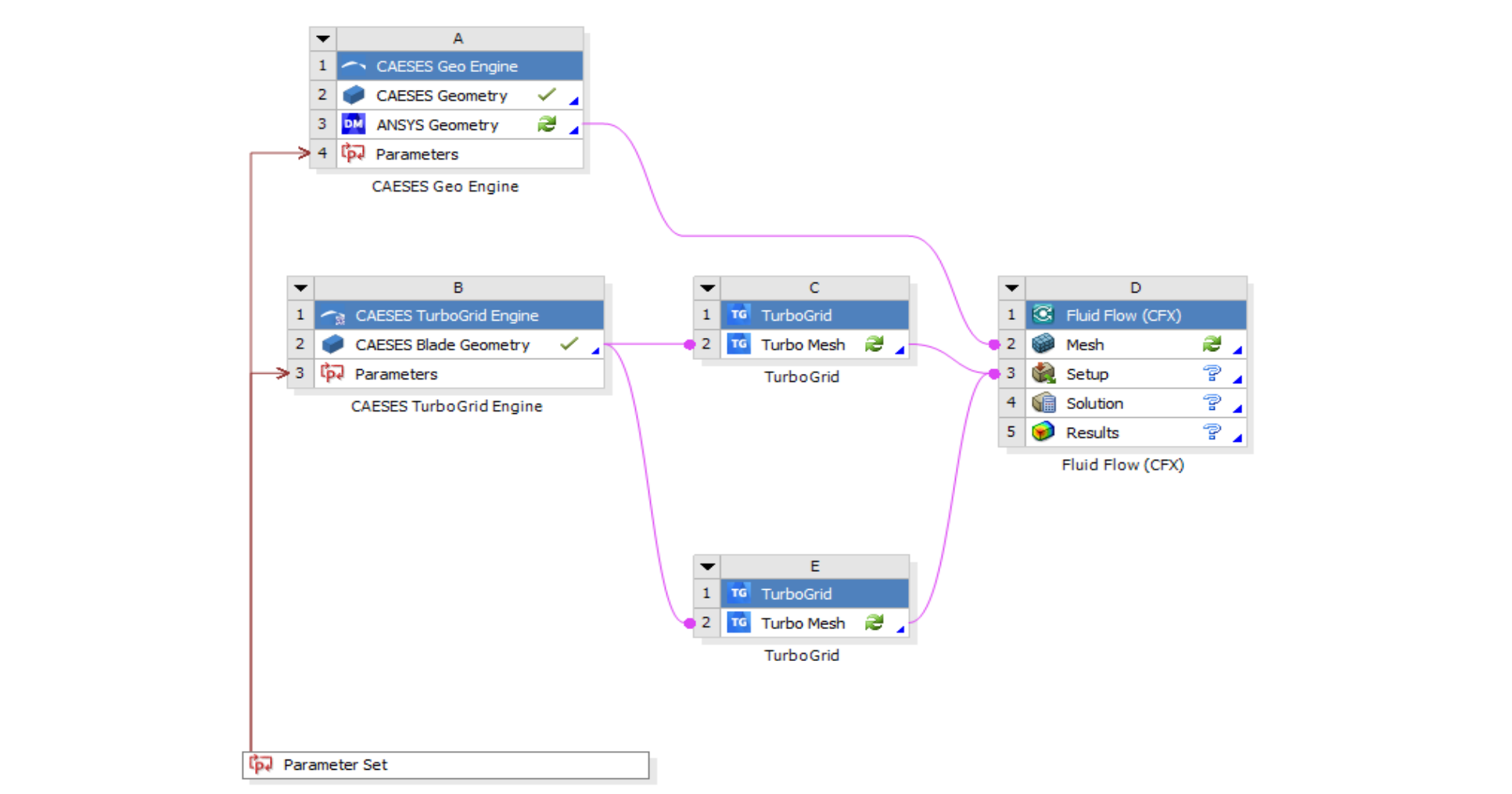
With the CAESES TurboGrid App, the full automation of the meshing and simulation process of new blade geometry variants can be realized without any additional scripting.
CAESES Workbench App
CAESES Workbench App is an ANSYS Workflow ACT Application, created to perform the automatic two way data transfer between ANSYS Workbench and CAESES.
Once installed, a new category "CAESES Geometry" is added to the ANSYS Workbench Toolbox, that includes;
- CAESES Geo Engine
- CAESES TurboGrid Engine
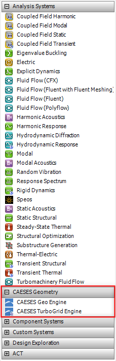
This tutorial describes how to install the CAESES Workbench App and use the CAESES TurboGrid Engine.
Making the CAESES Add-In Available
In order to make CAESES TurboGrid Engine available as an Add-In in the user interface of the ANSYS Workbench, we first need to install the CAESES Workbench App.
-
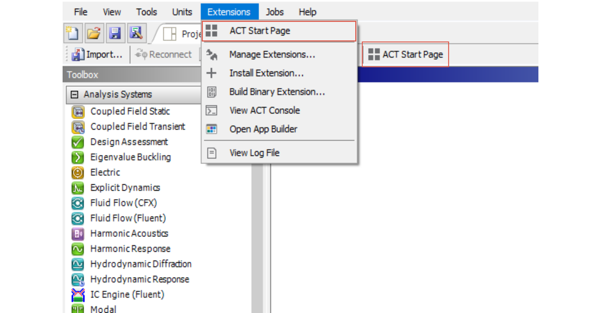
Within the ANSYS Workbench go to ACT Start Page.
-
In the opened ACT Start Page, click on “Manage Extensions”.
-
Inside Extension Manager, click on the "+" sign to install the CAESES Workbench App. You can find the referred app in your CAESES installation directory, under
etc > integration > ansys > CAESES_Workbench_App.wbex. -
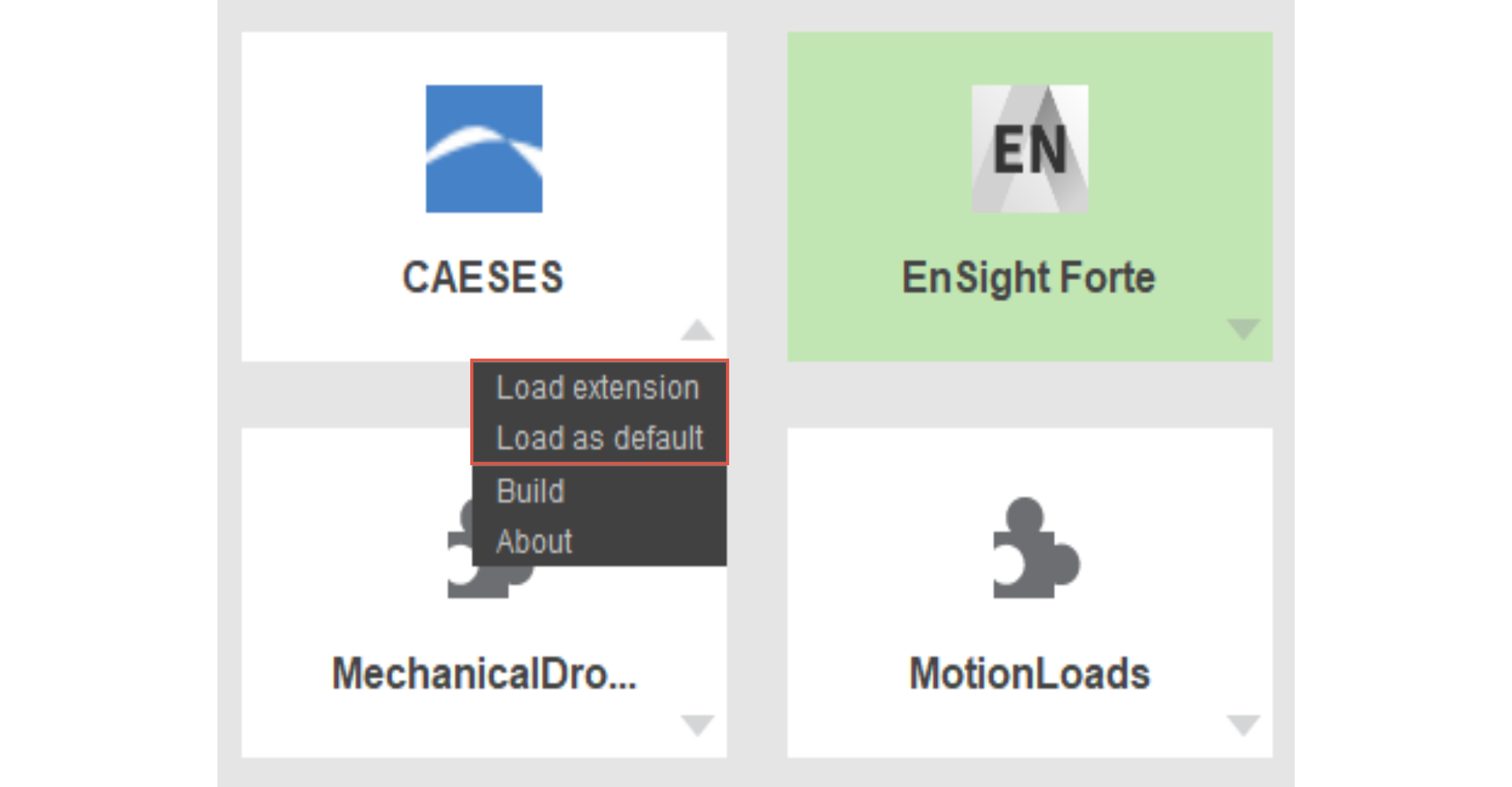
Click on the little arrow at the lower right corner of the CAESES TurboGrid App. Select “Load Extension” and “Load as default”.
- When you return to the Project Tab, the CAESES TurboGrid Engine should be visible on the left-hand side, under the category “CAESES Geometry”.
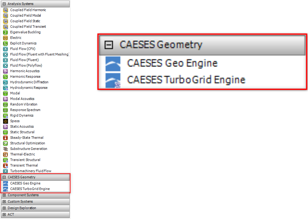
In case it does not appear, choose "View > Toolbox Customization", and activate the system “CAESES TurboGrid Engine” in the corresponding widget.
Design Variables
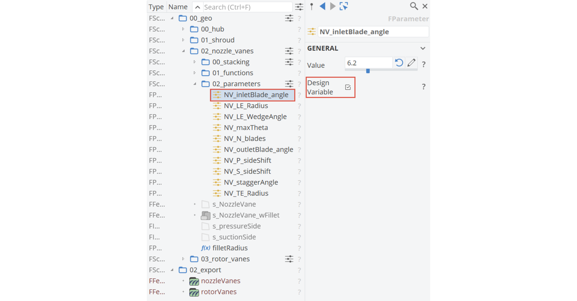
The goal is to generate blade geometry variants from within the user interface of the ANSYS Workbench. As a first step, we have to prepare the CAESES setup such that a parametric blade model is given and can be controlled through design variables.
In the ANSYS Workbench, the CAESES model will be updated in the background. CAESES is triggered in the batch mode, using the parameter input that you can enter in the ANSYS Workbench. These values are transferred to the design variables of your CAESES model, and a new blade geometry is exported directly to ANSYS TurboGrid. After having created the desired mesh for the first time, you can connect it to an analysis component, for instance.
Make sure that you have at least one design variable in your CAESES project. You can also optionally add the lower and upper bounds to the variables.
TurboGrid Export
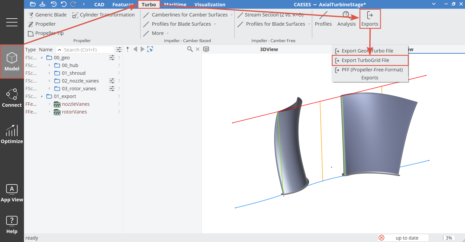
In this step, we use a shipped feature for the TurboGrid export. You can access the TurboGrid export feature as follows:
- In the menu, choose "Model > Turbo > Exports > Export TurboGrid File".
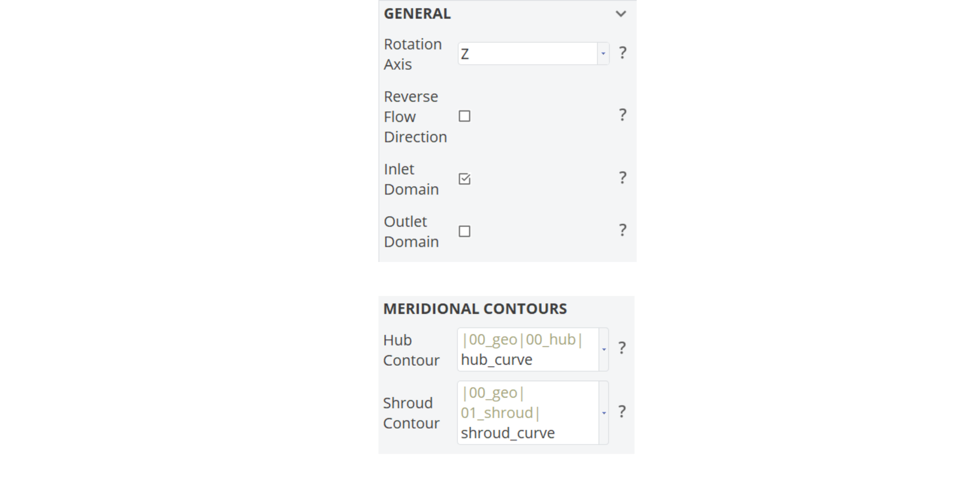
- Set all inputs for the created feature such as the blade geometry, the hub and shroud contours etc.
Note that you can also create several exports objects. For instance, if you have a stator and a rotor blade, then you would need two domains which is realized by using two exports:
Under "Main Blade" category, provide the necessary information like number of blades, pressure side and suction side geometries and if necessary LE/TE cut-off surfaces.
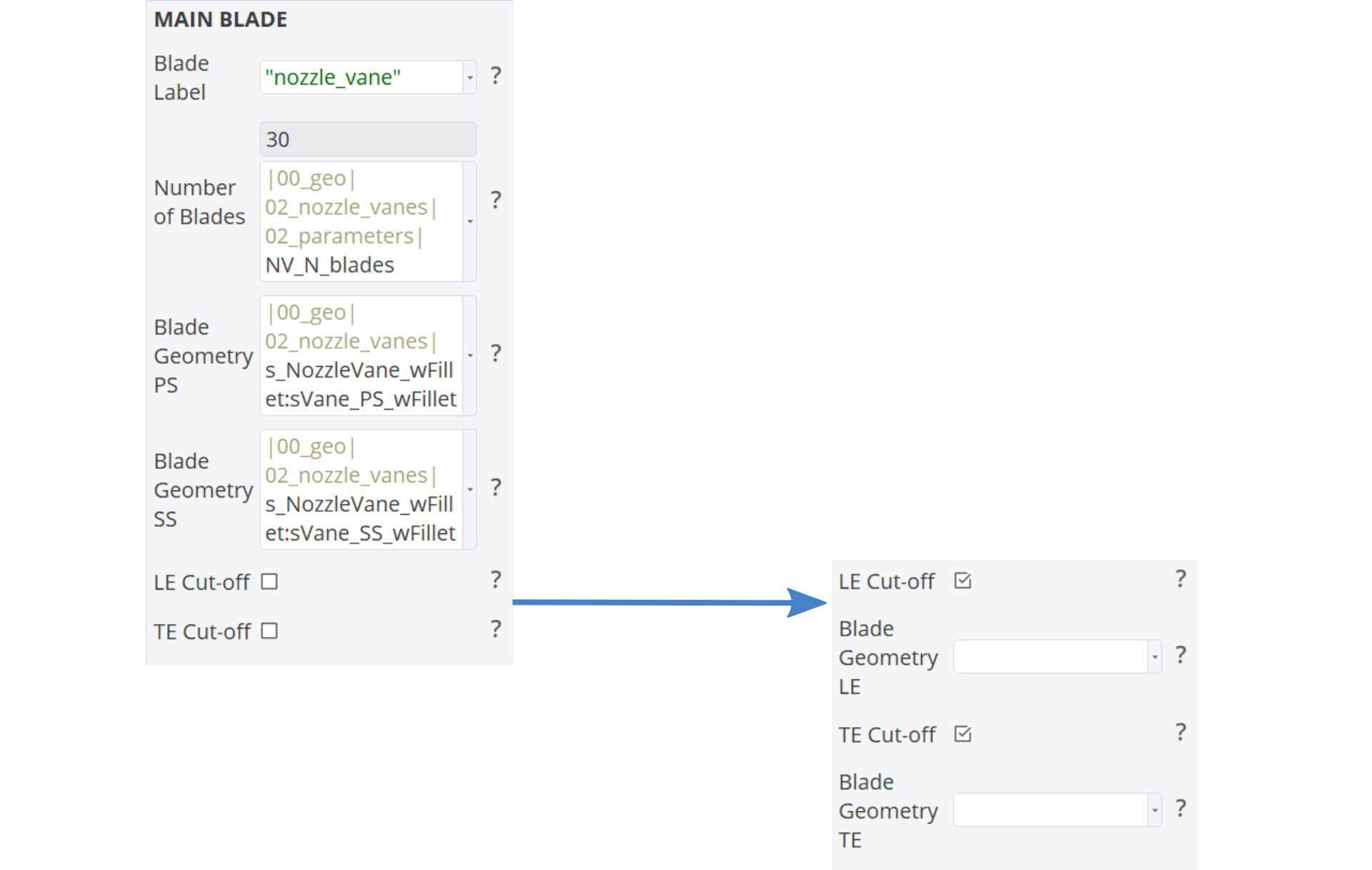
Do not forget to provide a blade label and be sure that it is a unique name for each feature.
There exist two different export methods:
Section Method : In addition to the blade geometry provided in the "Main Blade" category, the user is requested to input leading and trailing curves.
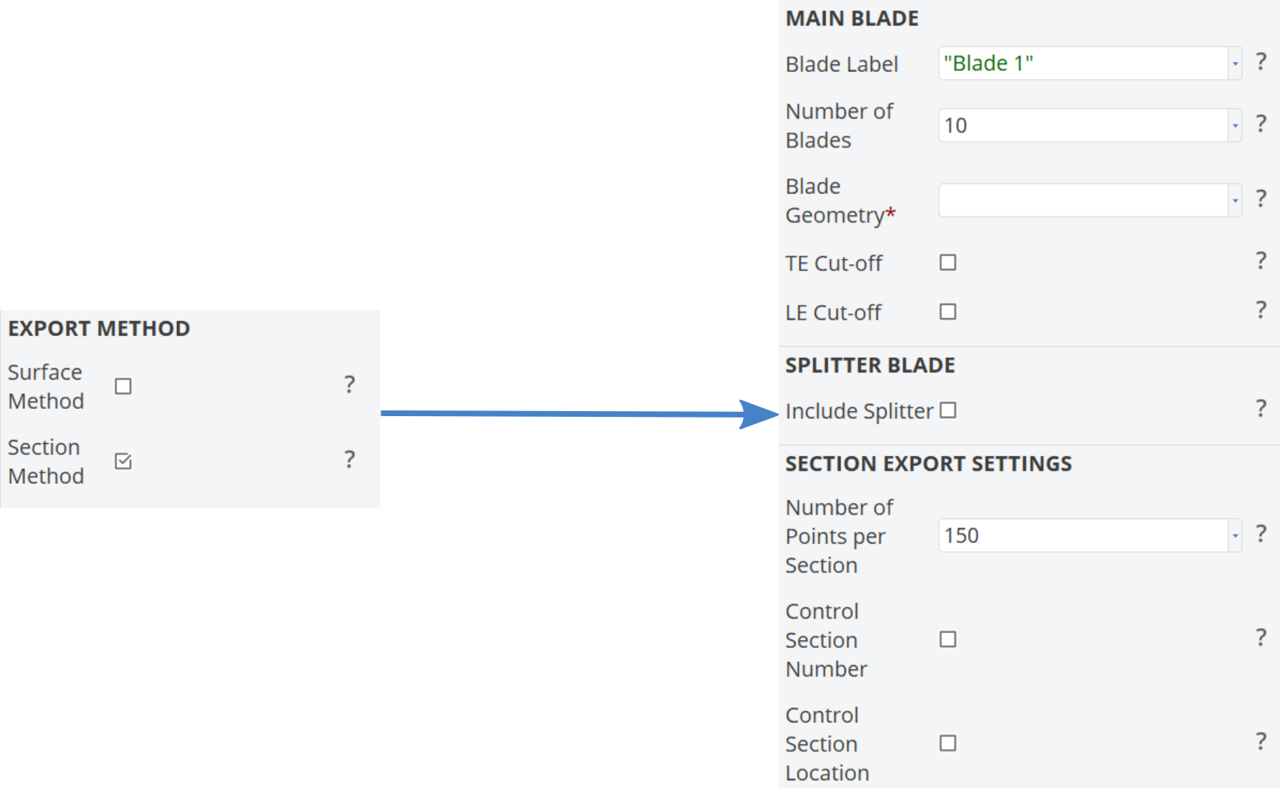
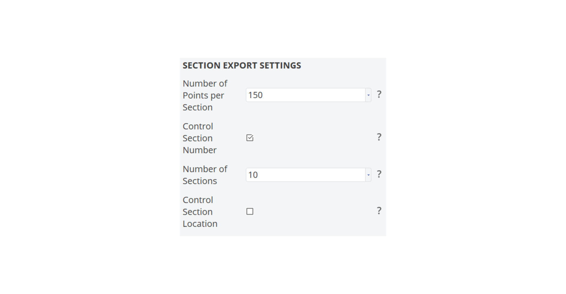
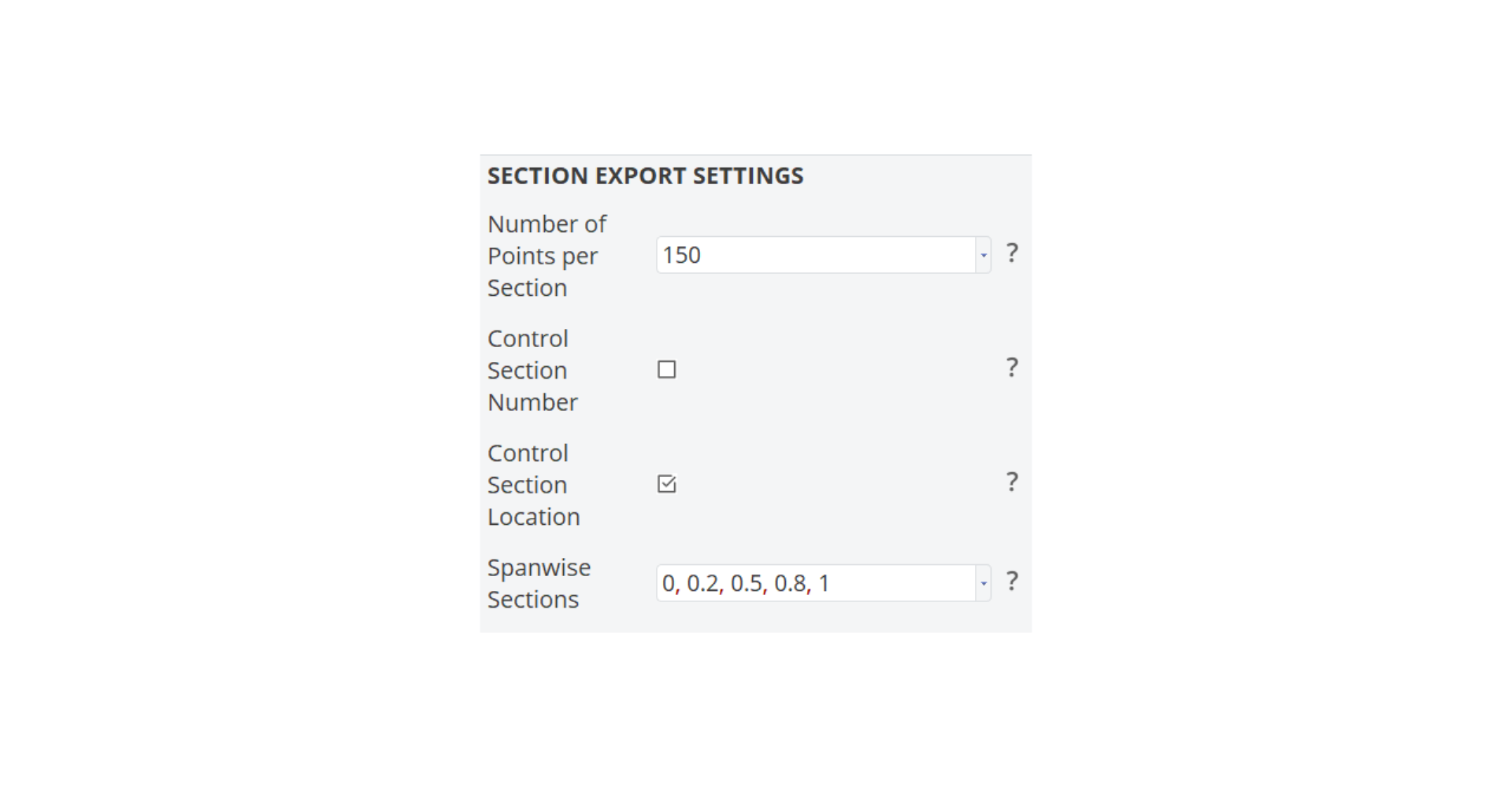
In order to control the section data, the user has two options:
- Select Control Section Number, which will provide equal distant spanwise sections
- Alternatively, select Control Section Location, which will let you specify spanwise locations.
Surface Method : The benefit of this method is that, the surface geometry is directly imported in TurboGrid. Hence the deviation caused by recreating the blade through section information is avoided. In addition to the blade geometry provided in the "Main Blade" category, the user is requested to input leading & trailing curves, pressure and suction side curves at the hub and shroud.
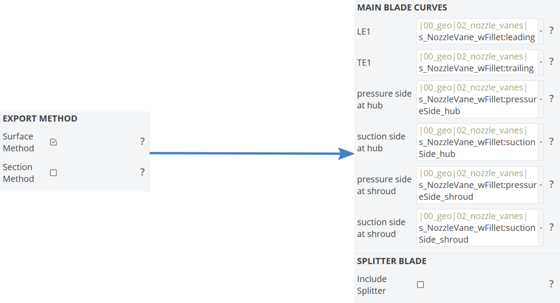
Check: Once you set up your TurboGrid export object in the tree, select it and update it. This generates the output files in the project directory (see the baseline directory manual_results) and lets you check the export setup.
Export the CAESES Script File (*.fsc)
Each CAESES geometry is an individual “configuration” of the TurboGrid Engine connection in the ANSYS Workbench. The CAESES TurboGrid Engine reads and exports the new parameters from ANSYS. It creates a new CAESES batch script file (*.fsc) for each design and runs CAESES with it in the background. The generated blade geometry is transferred to TurboGrid within the ANSYS Workbench as geometry input for the new design point. The CAESES TurboGrid Engine will create the same number of TurboGrid sessions as the number of created TurboGrid export features, or in other words, the number of your domains.
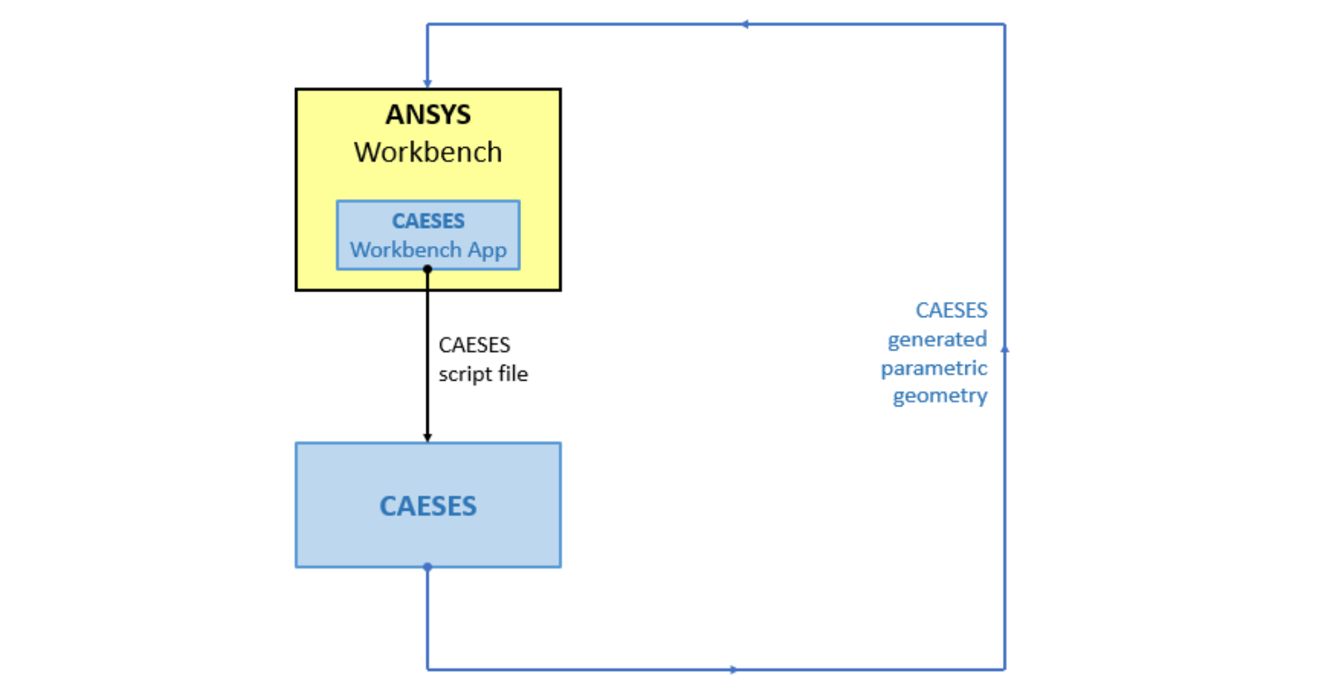
In order to create the control file (*.fsc), do the following:
- For an opened project in CAESES, choose "File > Export Script".
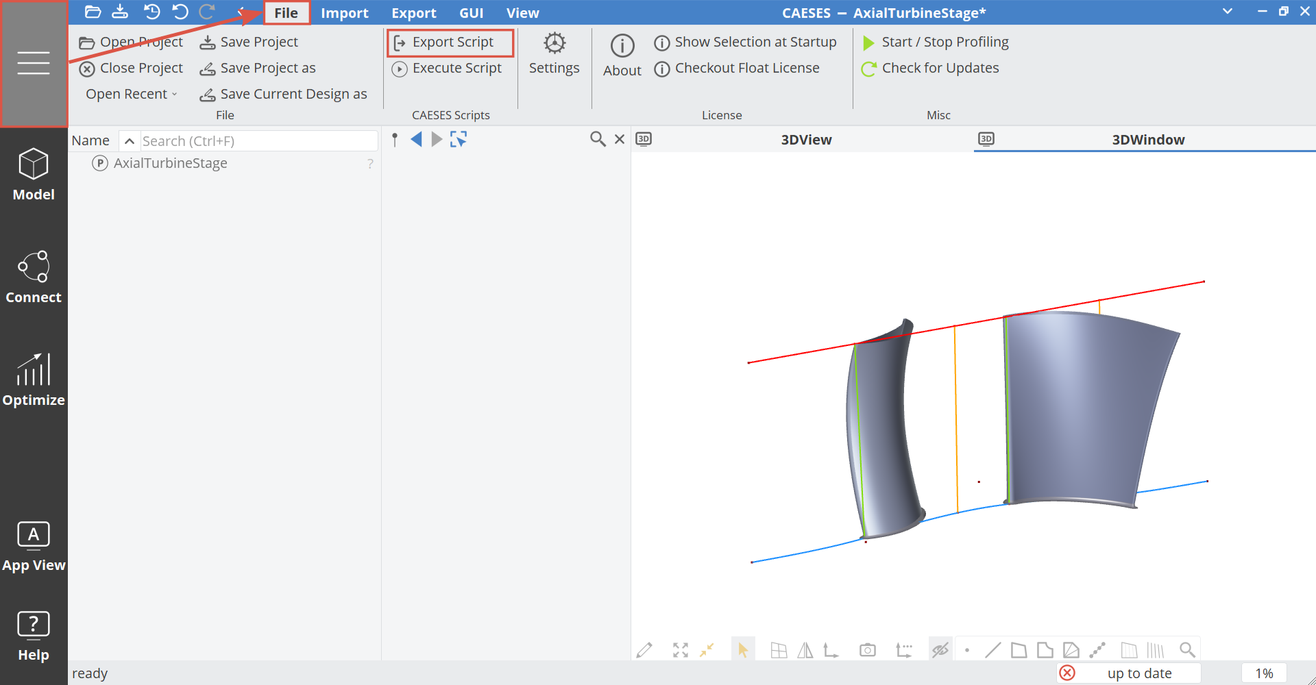
- Store it to a reference location on your PC.
- Close the CAESES project.
Within the fsc-file, the location of the CAESES project file and the CAESES binary location are specified which is used by the App. If you change the .cdb CAESES project file location, you have to edit and update the fsc control file (or recreate it through the GUI).
The CAESES control file and the project file do not have to be at the same location.
Load the Configuration into the ANSYS Workbench
The exported fsc-file from the previous step contains all information for integrating a specific CAESES setup into the ANSYS Workbench:
- Drag & drop a CAESES TurboGrid Engine instance into the "Project Schematic" of ANSYS Workbench so that a new system gets created.
- In the context menu of the “CAESES Blade Geometry” component, choose "Select an FSC file…".
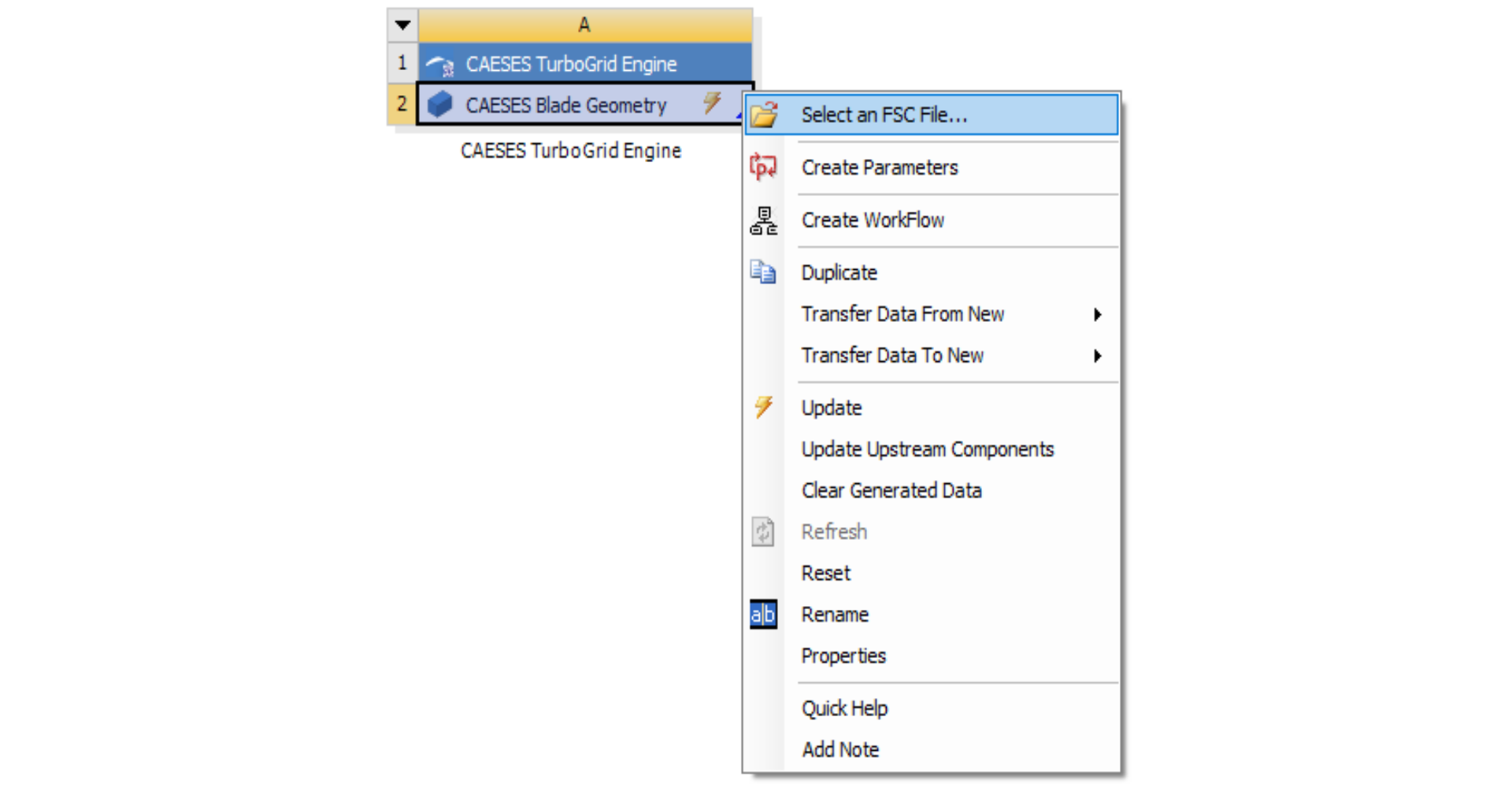
- Select the fsc-file that you have exported previously.
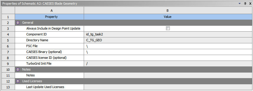
- Alternatively, one can mention the file location in the Geometry Property box by setting the “FSC file” input.
-
Optional: In this box, the “CAESES Binary” is also an optional input, and needs not to be filled unless a different CAESES version is desired to be used.
-
Optional: In this box, the “CAESES license ID" is also an optional input, and needs not to be filled unless the user wants to use a specific CAESES license.
-
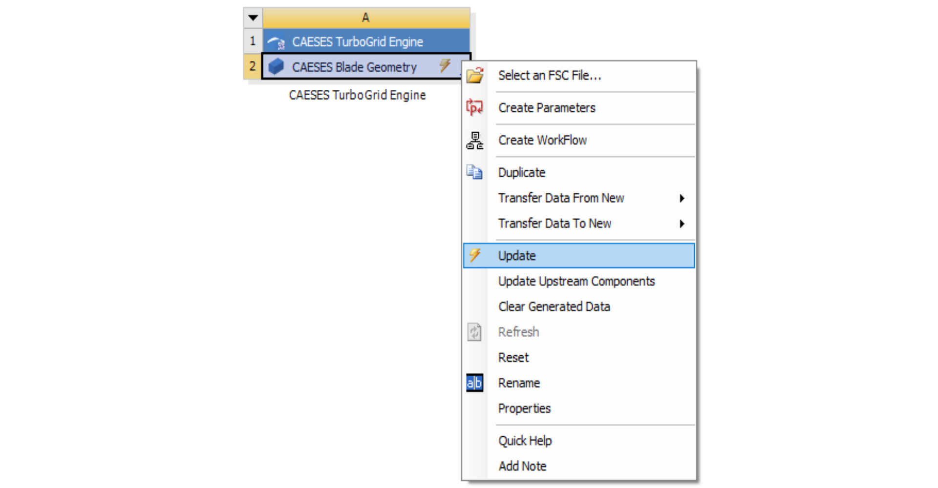
Choose “Update” to run CAESES in the background, and to create geometry.
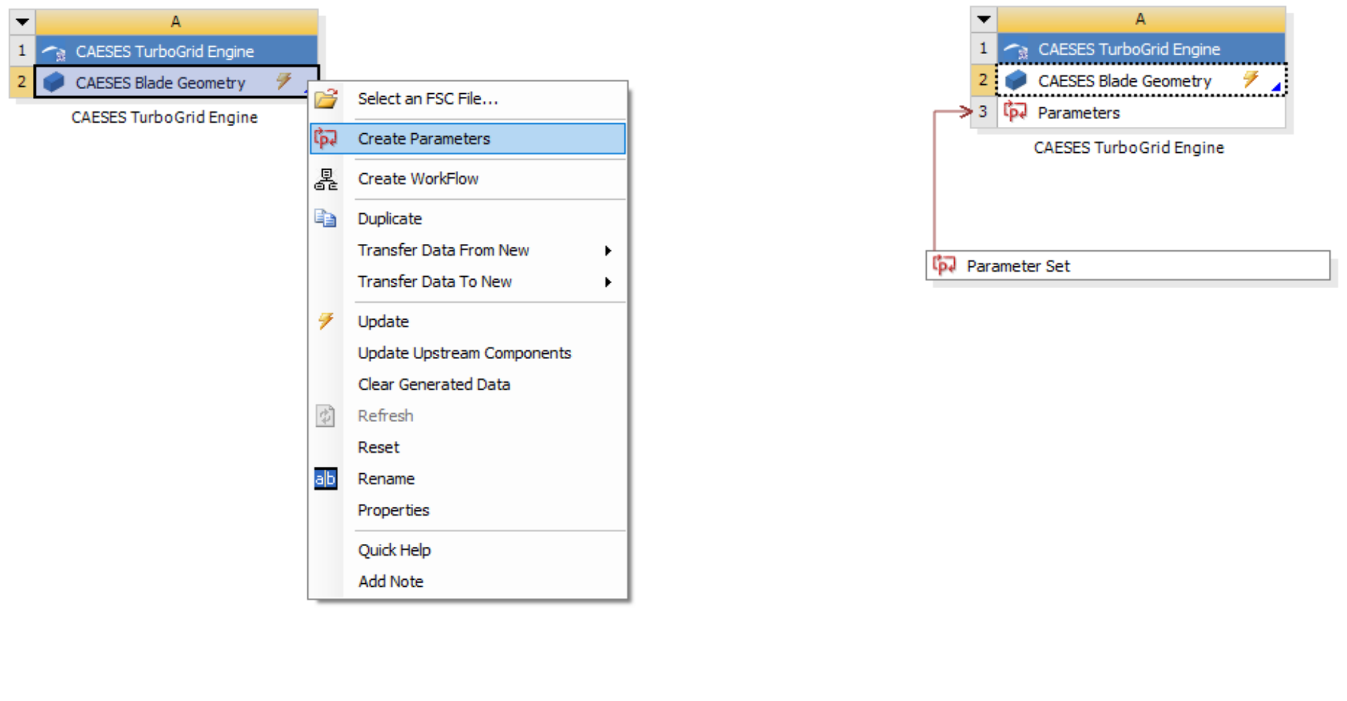
- Within the context menu, “Create Parameters” serves to create the parameter set by the user beforehand. Note that this operation will be triggered automatically during the general update process.
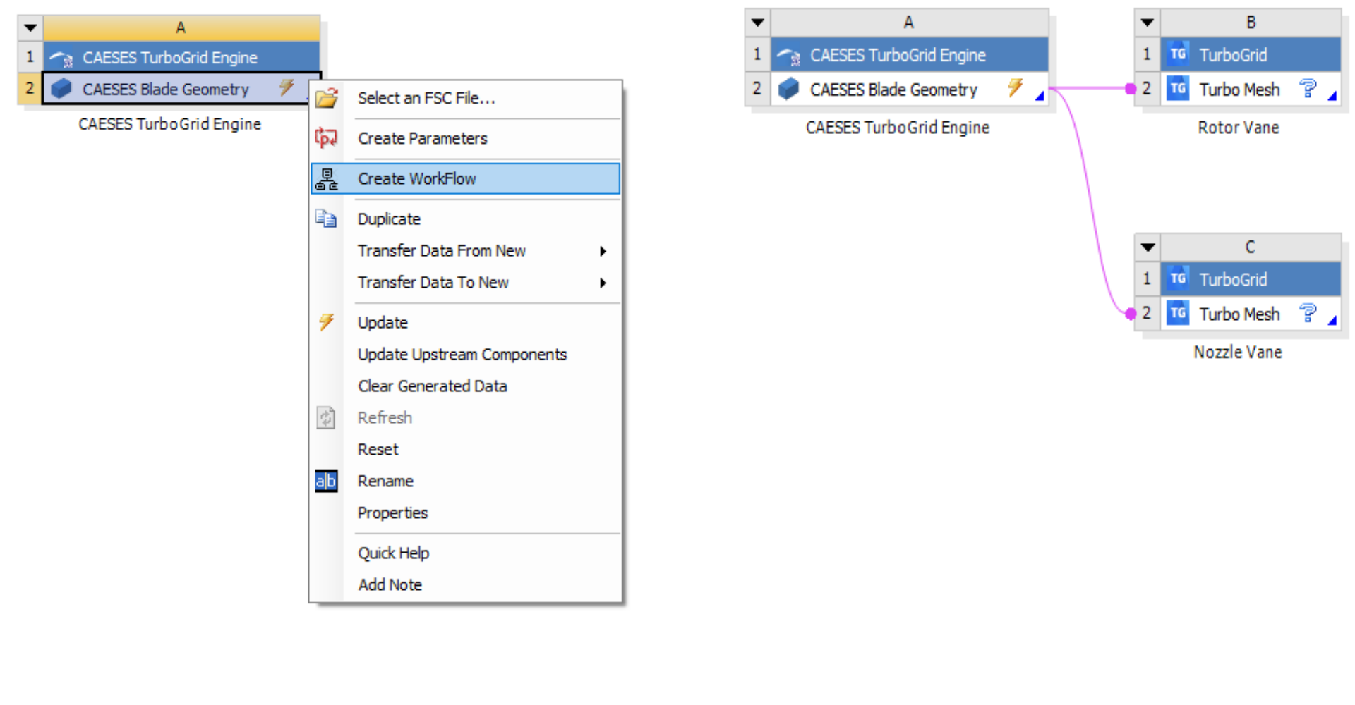
- Within the context menu, “Create Workflow” serves to create the connected TurboMesh systems beforehand. Note that this operation will be triggered automatically during the general update process.
Continue Work in ANSYS Workbench
Now your CAESES geometry engine is ready and can be used. You can connect the component to the meshing, and you can change parameters:
- For the meshing component, choose “Transfer Data to New” in order to connect it to other containers of the ANSYS Workbench.
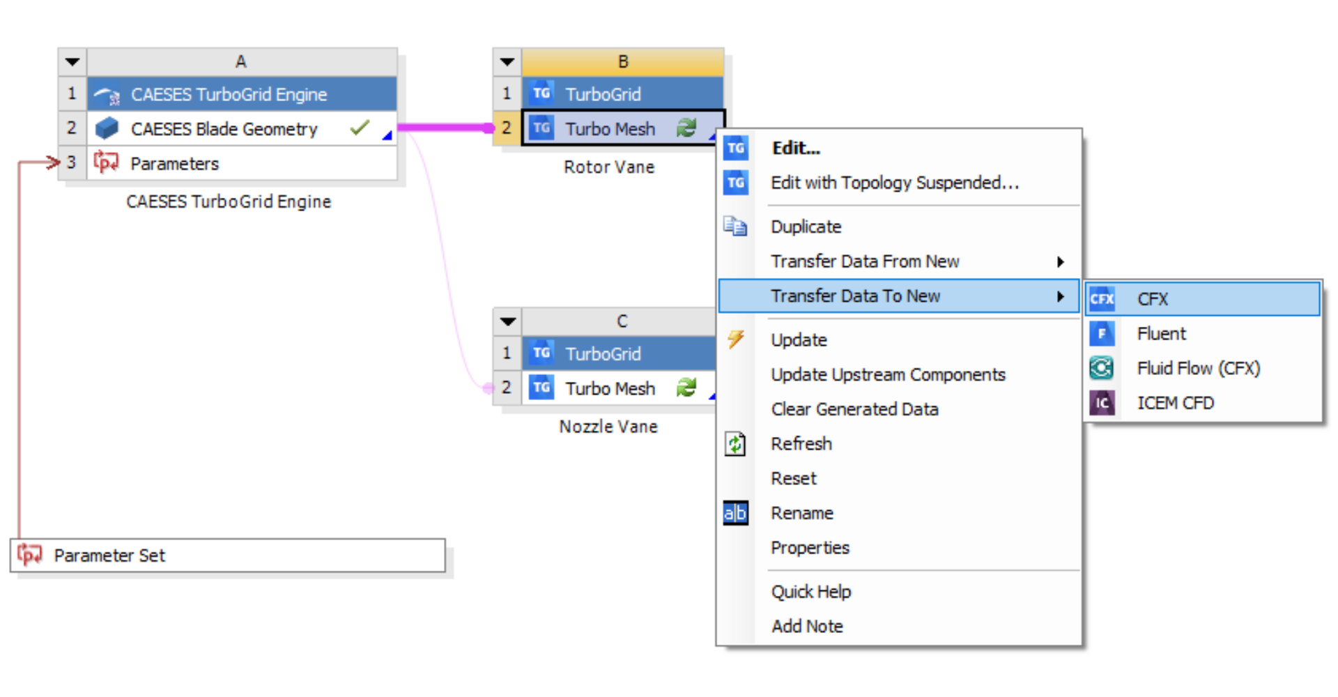
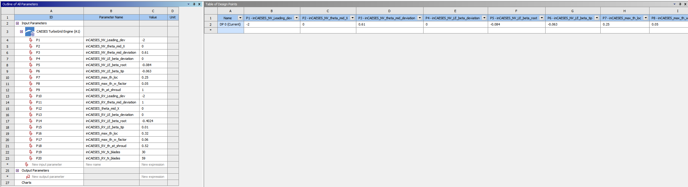
- By using double-click on the “Parameter Set”, you can directly change the design variables of the CAESES model. An update of the design point(s) triggers CAESES in the background again.
CAESES Project File
If you want to take a look at the finalized model you can find the resulting CAESES project file ansys-workbench-turbo-grid-app.cdb here: