CAESES Tutorials
The CAESES tutorials provide step-by-step guides and ready-to-download example models for engineers working on parametric geometry design and automated CFD optimization. Coverage spans marine propellers (conventional, toroidal, tipr rake, and contra-rotating), turbomachinery (axial and centrifugal compressors, pumps, fans, and volutes), ship and boat hull design, piston bowls and intake port components, and general morphing techniques. Each tutorial walks through a complete workflow — from geometry parameterization and design variable setup to automated solver connections with tools like StarCCM+, OpenFOAM, ANSYS Workbench, ShipFlow, and NavCad.
New here? Start with the First Modeling Steps tutorial, then continue by topic.
Get Started
Learn the CAESES interface and core concepts: build parametric geometry from scratch, set up design variables, and run your first automated geometry variation study.
First Modeling Steps
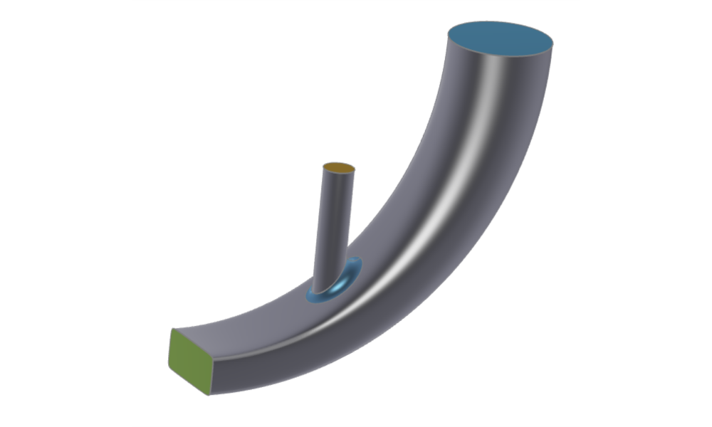
Simple duct sweep surface, which blends the sections from start and end linearly; includes an intake cylinder.
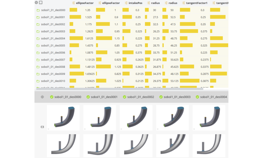
Geometry Variation and Assessment
Automatically vary geometry by using design variables and design engines.
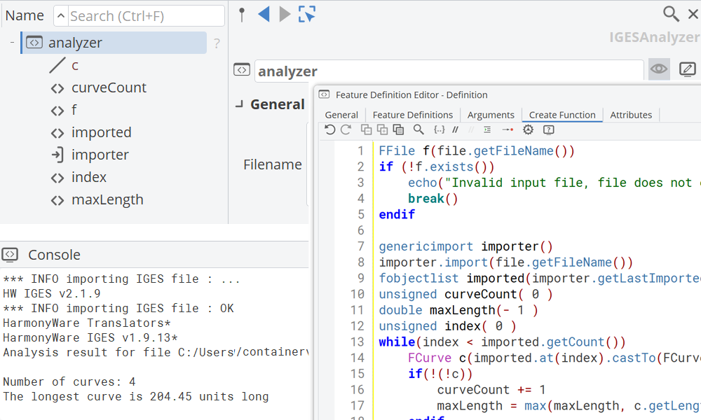
Features
Learn CAESES feature programming — the built-in scripting language for conditional logic, loops, and custom functions that automate parametric geometry generation.
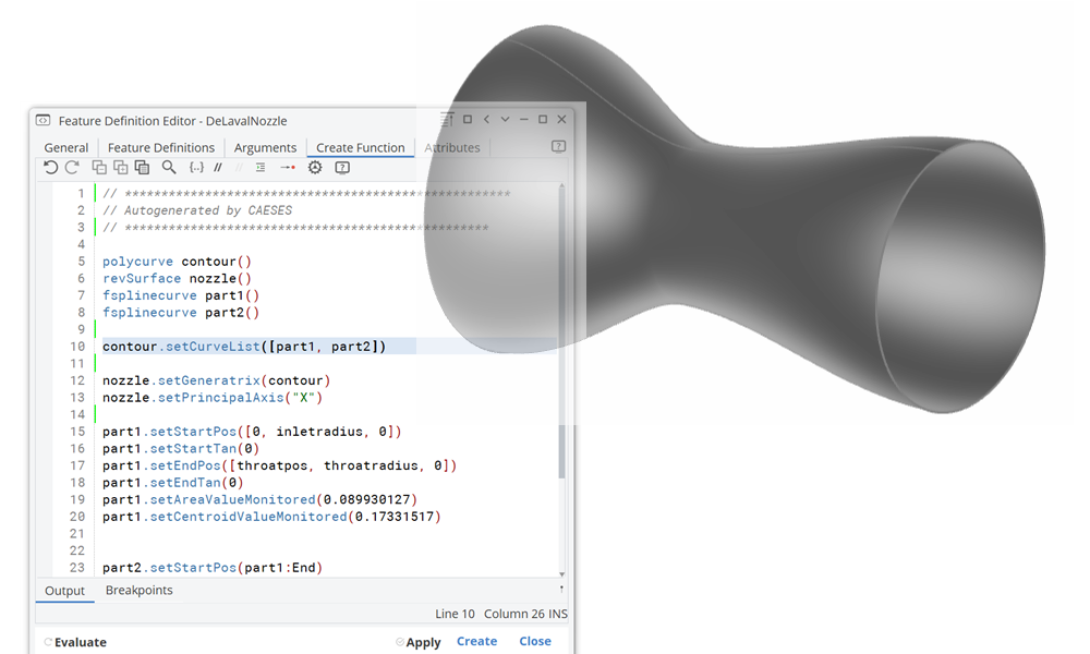
Introduction to Features - Nozzle
Learn the basics of feature programming.
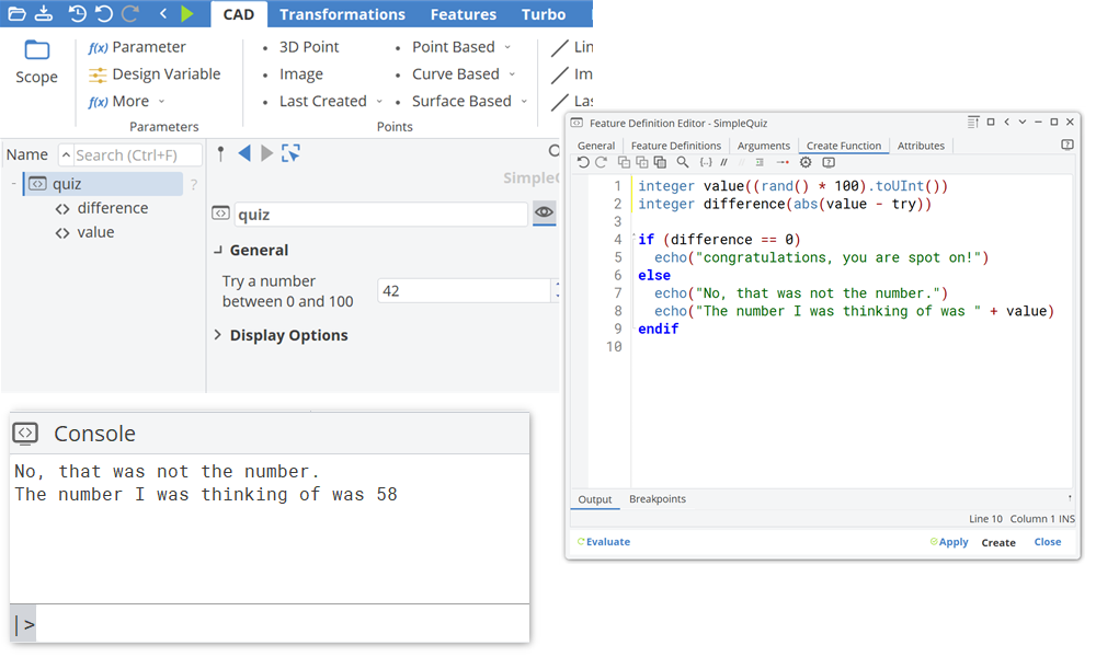
Case-by-Case Analysis
Using conditional structures (if/else) to perform case-by-case analysis.
Loops
Implement iterative algorithms by using the various options to implement loops.
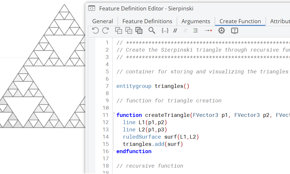
Functions
Defining Functions allows to structure the code of a feature definition in sub execution units.
Meta Surface
Explore the Meta Surface entity, which gives fine-grained control over section parameters along a sweep path — the foundation for volutes, ducts, and other complex swept geometries.
Meta Surface Creation
Duct with detailed control of the parameters within the sweep.
Morphing
Apply mesh morphing and BRep morphing to deform existing geometries — STL meshes or imported STEP/IGES/NURBS surfaces — without rebuilding from scratch. Check out the maritime morphing tutorials to see these techniques applied to ship hulls.
Mesh Morphing
Free form editing tool used on discrete STL geometries with STL export.
BRep Morphing
Allows you to manipulate (imported) NURBS based geometries such STEP, IGES, SAT, PARASOLID with NURBS based export.
Software Connection
Set up CFD automation pipelines by connecting CAESES to external solvers — driving geometry changes directly into solver runs and reading back results for optimization.
General Connection
General-purpose solver connections covering StarCCM+, ANSYS Workbench, and OpenFOAM for arbitrary geometries.
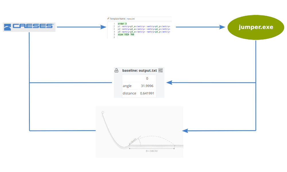
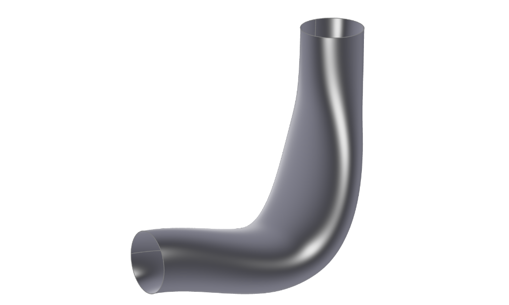
Basic Connection - Jumper
Starting point to learn the general setup of a software connection.
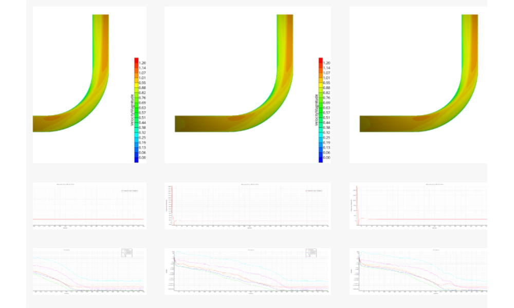
General StarCCM+ Connection
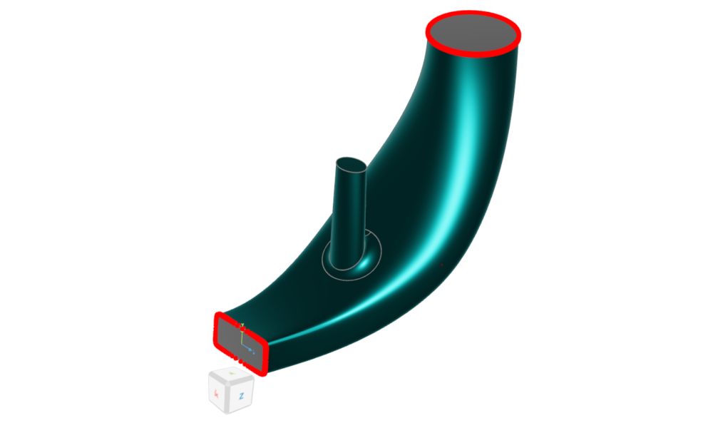
General StarCCM+ connector setup for a 90 degree duct.
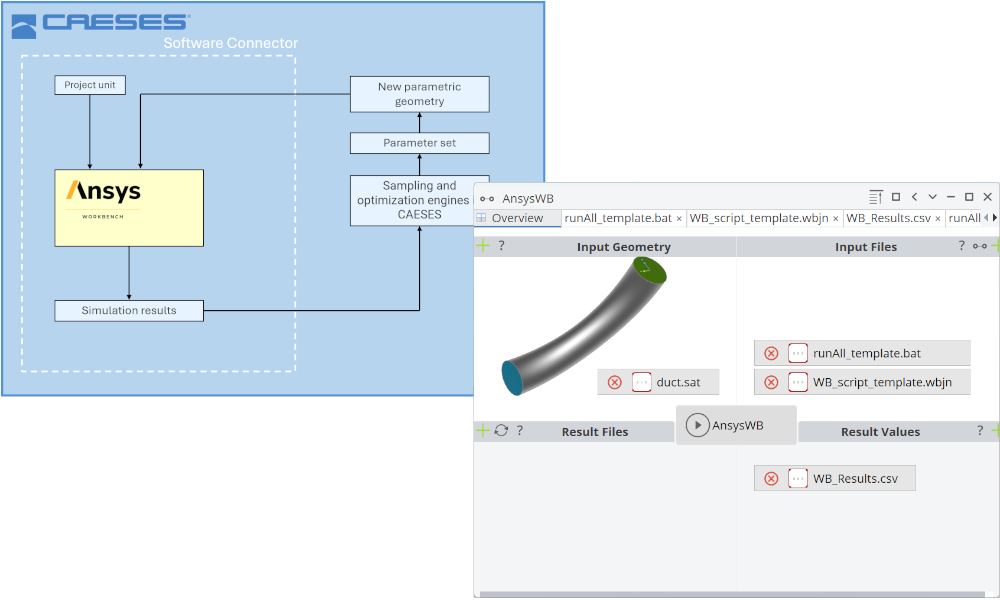
ANSYS Workbench Connection
ANSYS Workbench included inside CAESES using the Software Connector.
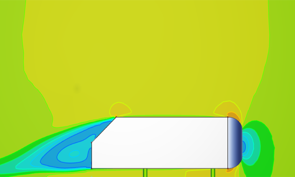
Ahmed Body with OpenFOAM
Modeling of an Ahmed Body and a OpenFOAM software connection setup.
For Ship Hulls
Pre-configured maritime CFD connectors for StarCCM+, OpenFOAM, ShipFlow, NavCad, Maxsurf, and FINE/Marine — for ship resistance, seakeeping, and propulsion optimization.
Shipflow Connection
A step-by-step shipflow connection setup.
openFOAM Connection
Shows how to setup the pre-configured OpenFOAM connector for a ship based on the ship modeling workflow.
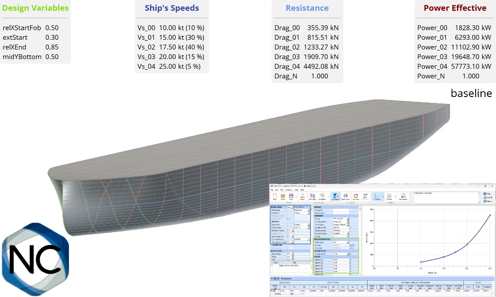
NavCad Connection
Learn how to connect NavCad with CAESES for hydrodynamic and propulsion system optimizations.
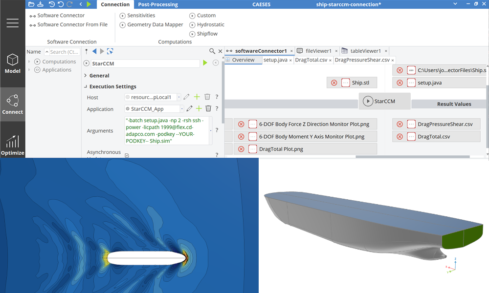
Maritime StarCCM+ Connection
Shows how to setup the pre-configured StarCCM+ connector for a ship based on the ship modeling workflow.
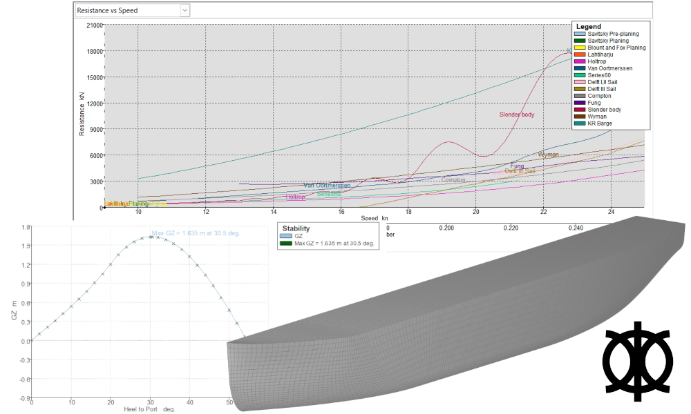
Maxsurf Connection
Connect Mawsurf for stability and resistance calculations.
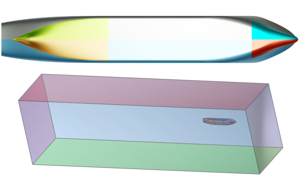
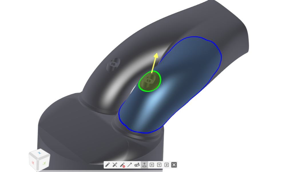
Fine Marine Pre-Processing
Boundary conditions setup by assigning colors in CAESES, for HEXPRESS mesh generation with a colored STL as export format.
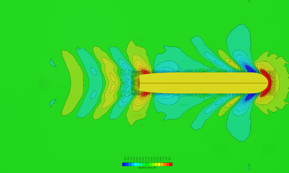
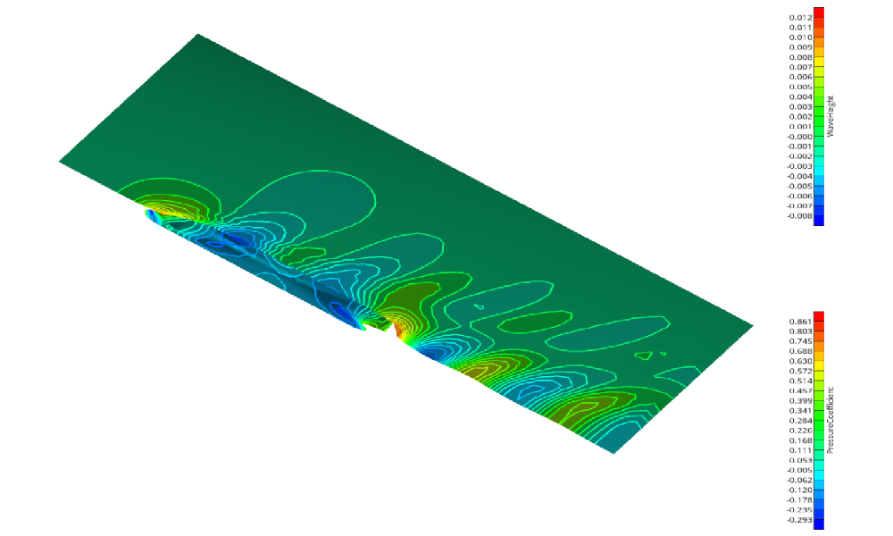
Naval CFD Post-Processing
Setup of a Reynolds-transformation of integral values as well as preparation of visualizations.
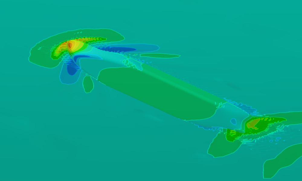
CFD Results Comparison
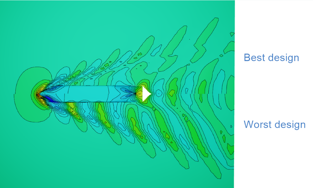
How to compare CFD results in the 3D view using the default ship from the Ship Modeling Workflow, evaluated using a simple SHIPFLOW setup.
Optimization
Drive geometry optimization with automated design variable variations, principal component analysis (PCA) for dimensionality reduction, and advanced multi-objective strategies using Dakota.
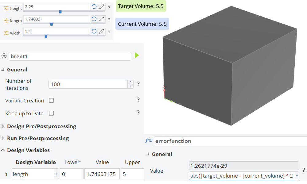
Fulfilling Geometry Constraints
Reach the volume target by automatically adjusting the length for each design variant.
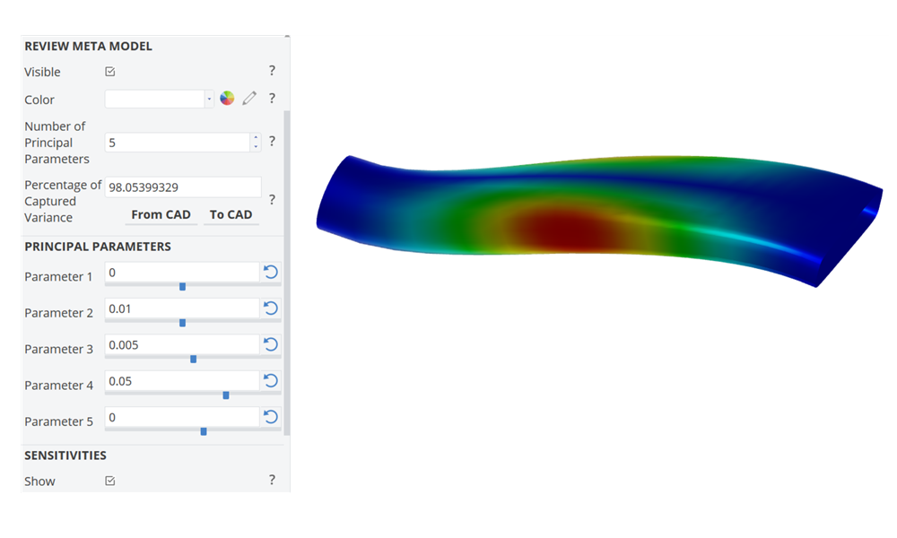
Dimensionality Reduction with PCA
S-duct variation based on a principal component analysis to reduce the number of free design variables.
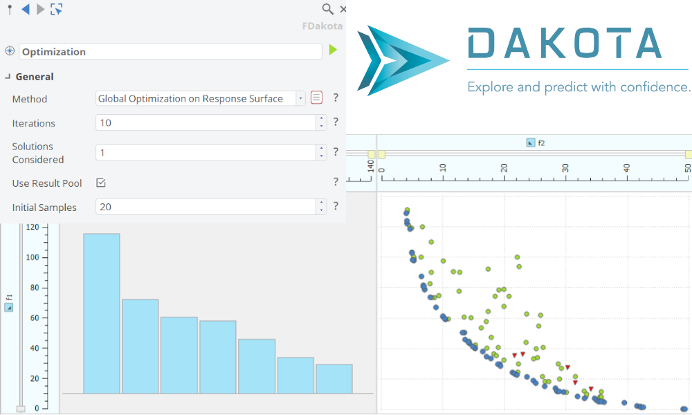
Dakota - Advanced Optimization Strategies
Best practice for sampling methods and response surface based optimization.
Integrations
For ANSYS Workbench
Run CAESES as an external parametric geometry engine inside ANSYS Workbench — as a Geo Engine for general shapes or as a TurboGrid Engine for turbomachinery blade meshing.
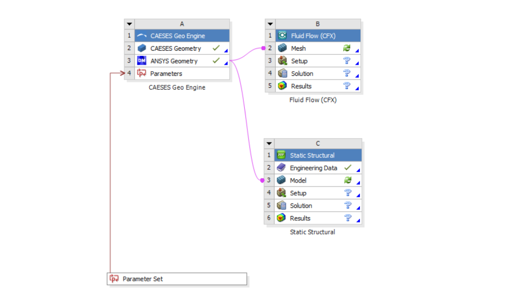
CAESES Geo Engine
Use CAESES as an external parametric geometry generator inside the ANSYS Workbench platform.
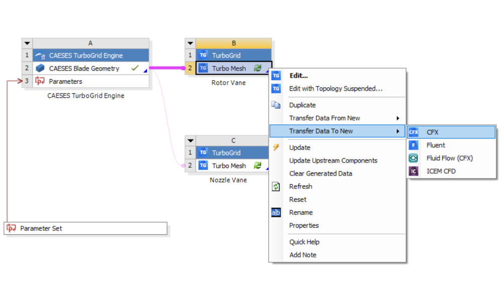
CAESES TurboGrid Engine
Use CAESES as an external parametric blade geometry generator within the ANSYS Workbench for use with TurboGrid
Turbomachinery
Parametric design tutorials for turbomachinery components — from individual blade profiles to complete compressor and pump casings.
Blade Design
Design turbomachinery blades using profile-based and cylinder transformation methods, covering axial compressors, centrifugal pumps, and analysis tools for imported blade geometries.
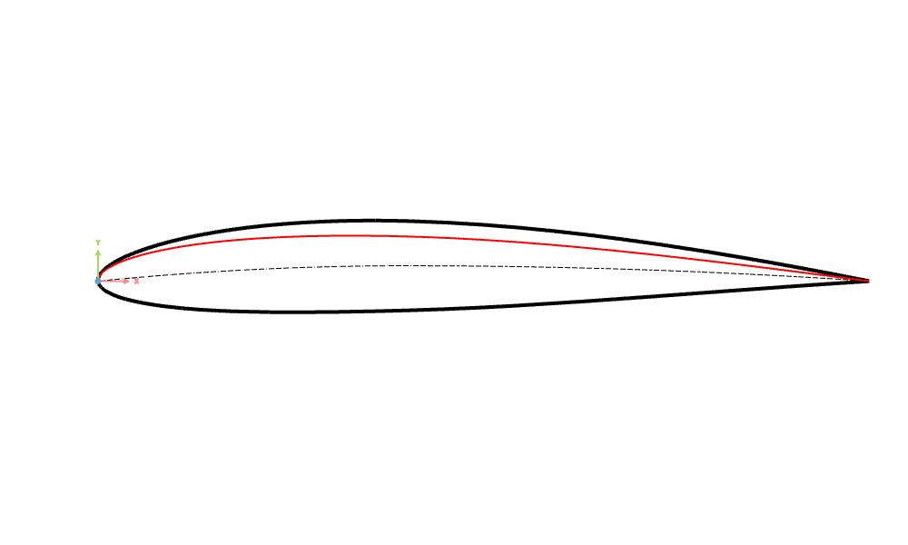
Profile Design
Cylinder Transformation
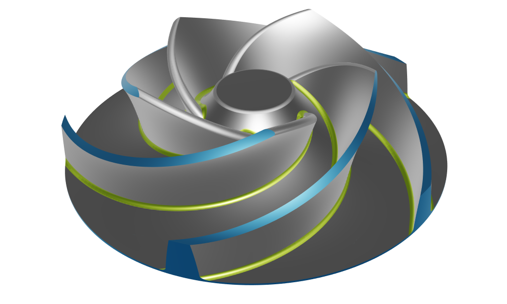
Centrifugal Pump
Centrifugal pump with constant radius fillets
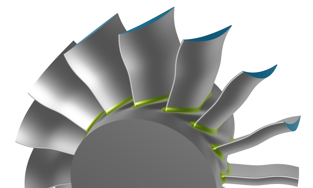
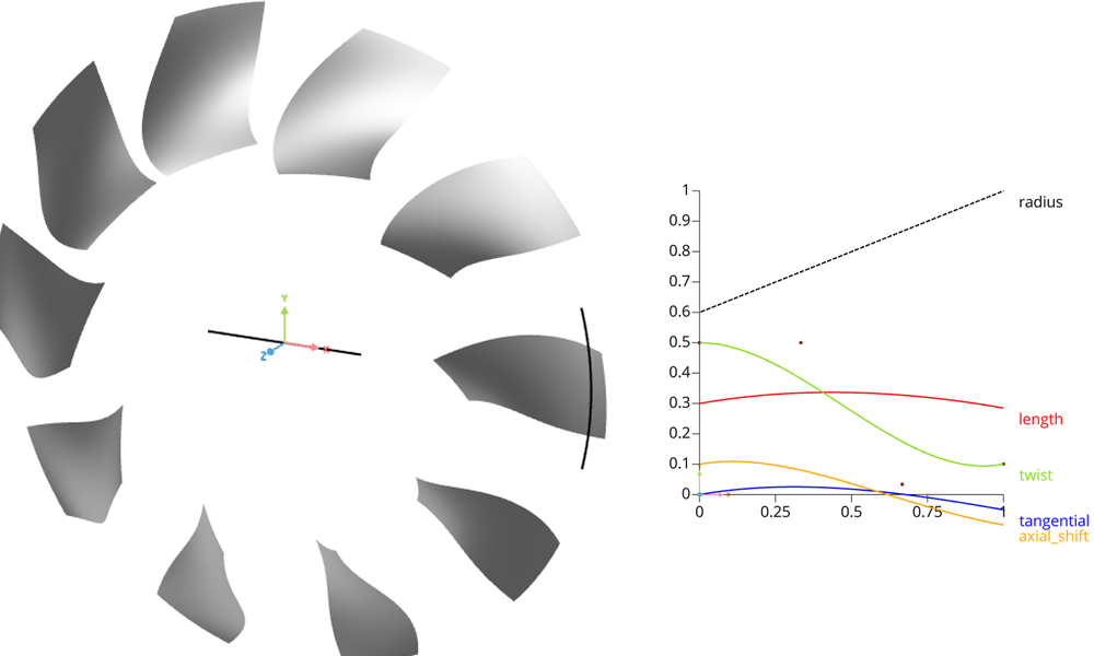
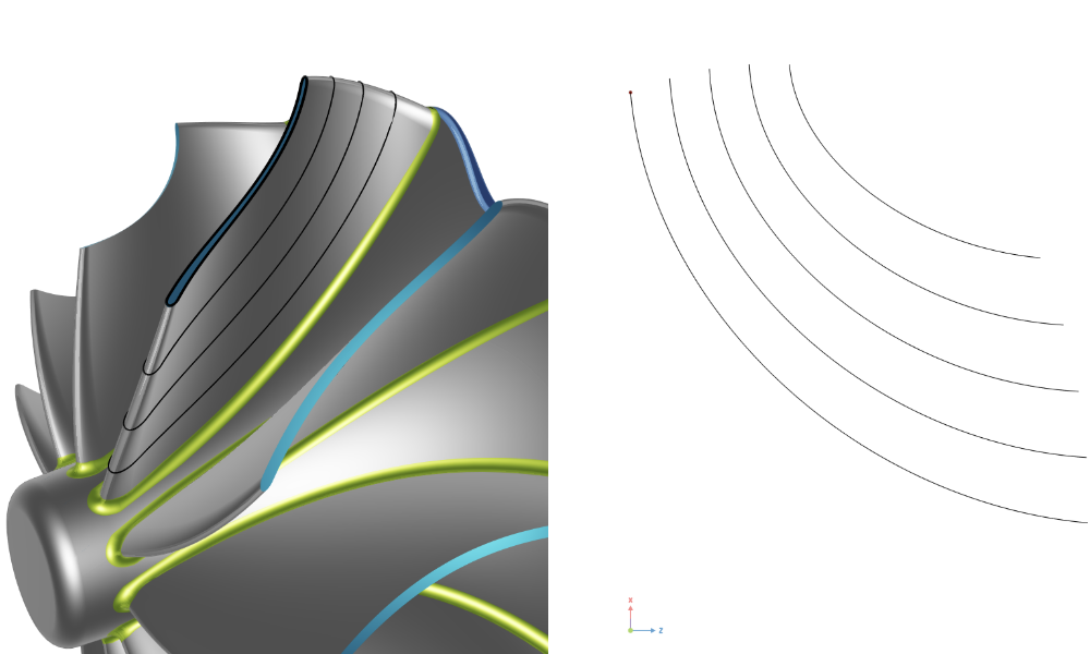
Axial Compressor
An axial compressor stator with a constant radius fillet
Analysis Tools for Imported Blades
Analyze imported geometries to extract the main characteristics
Volute
Build parametric volute geometries with automated area-to-radius (A/R) ratio control — the standard starting point for centrifugal compressor and pump casing design in CAESES.
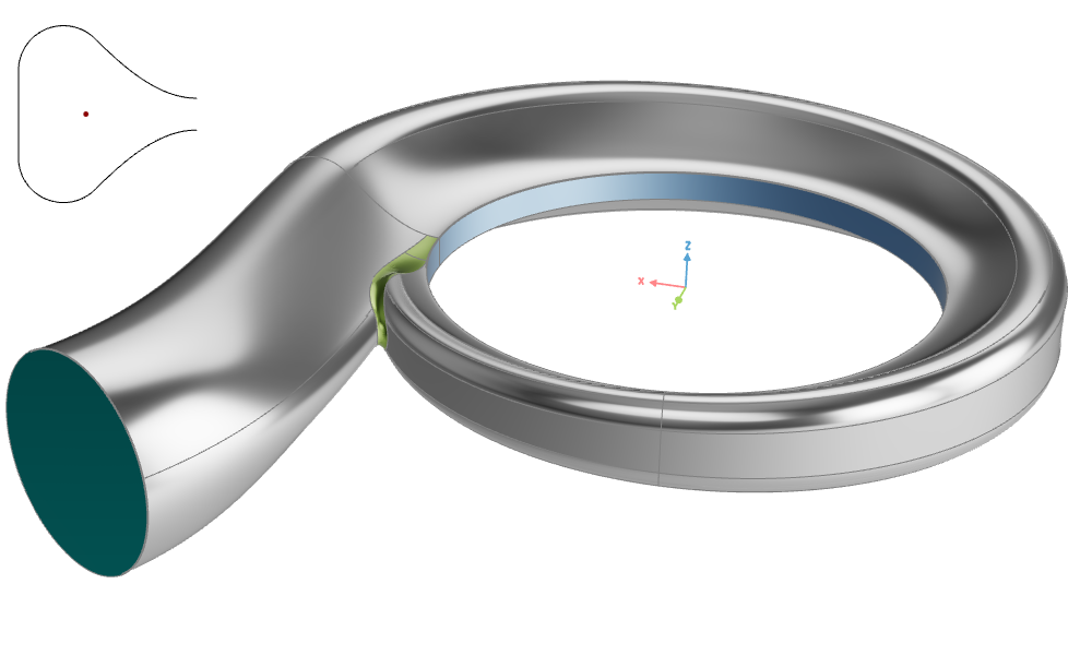
Volute Design
A symmetric volute with automated Area to Radius (A/R) adjustment based on tutorial profile section 3.
Propeller
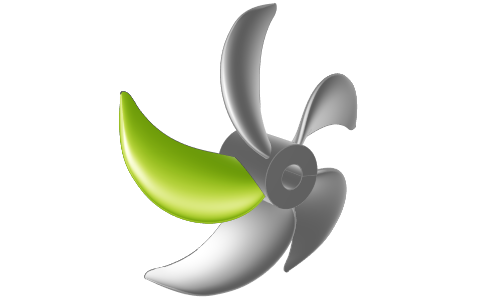
Design marine propellers parametrically — covering conventional blades with tip rake and high skew, profile import workflows, toroidal (looped-blade) propellers, and built-in analysis tools for cavitation prediction, expanded area ratio, and propeller performance.
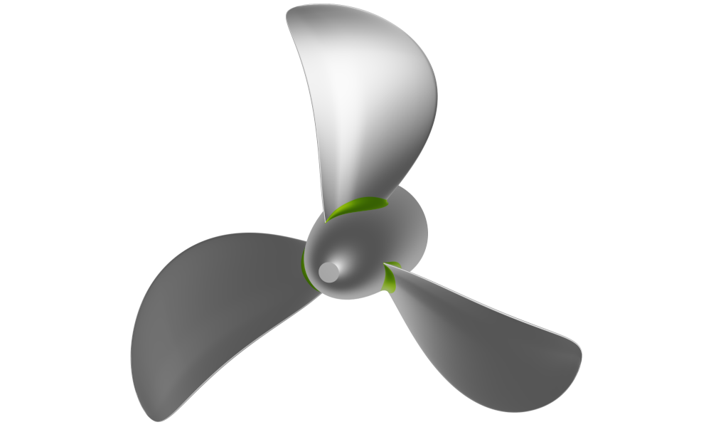
Advanced Propeller Workflow
Parametric propeller model from start to finish with option to include a tip rake or highly skewed blades.
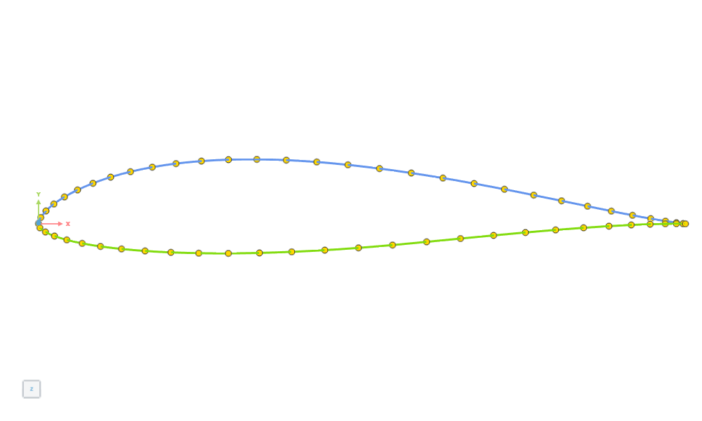
Import Propeller Profiles
Create a propeller importing a 2D profile from an ASCII file (.dat format) or by importing an existing profile as a Curve.
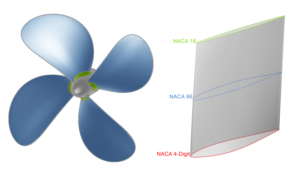
Propeller with Different Profiles
Create a propeller by using different profiles and generating a Profile Surface.
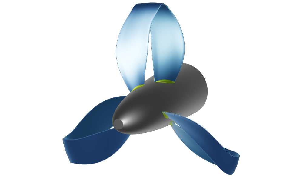
Toroidal Propeller Workflow
Step by step guide to create a fully parametric toroidal propeller in CAESES.
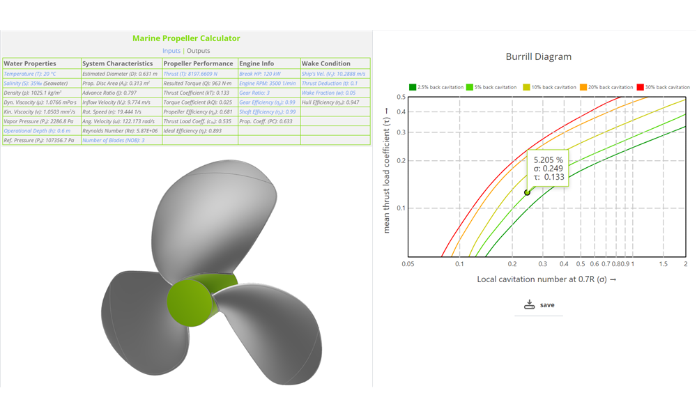
Propeller Analysis Tools
Learn more about the cavitation prediction, minimum thickness, slip percentage and expanded area ratio and propeller property calculations as well as analysis tools.
Generic Blade Design
Used to export PFF files (Propeller Free Format) with open trailing edge and open tip.
Maritime
Tutorials for naval architects and hydrodynamic engineers: parametric hull modeling, morphing of imported geometries, and hydrostatic analysis.
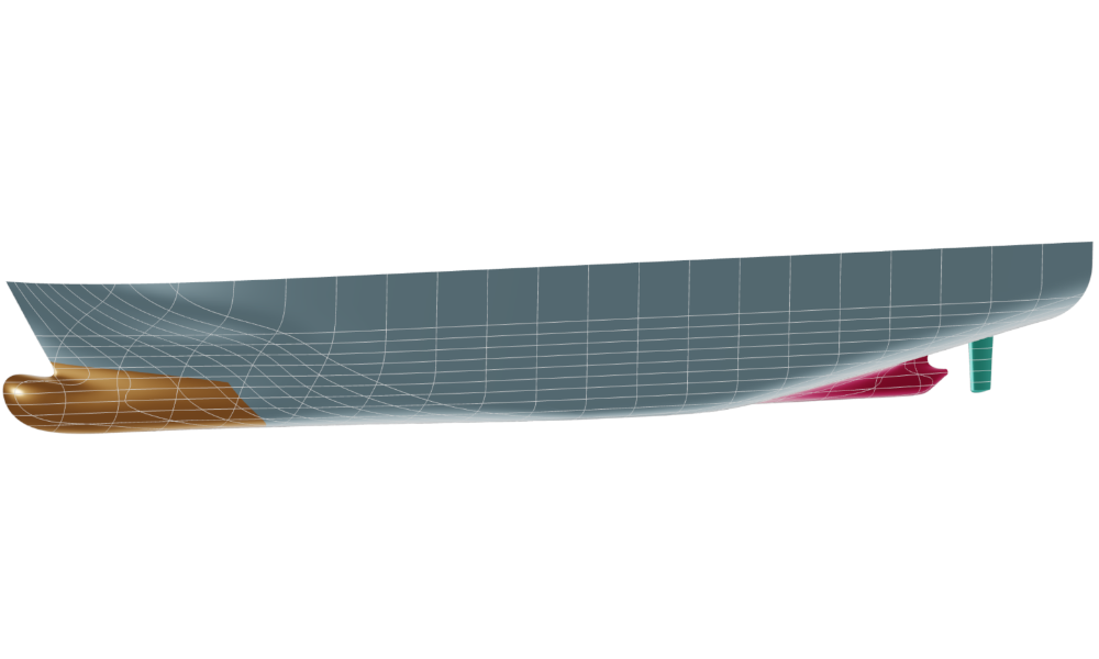
Ship Hull Design
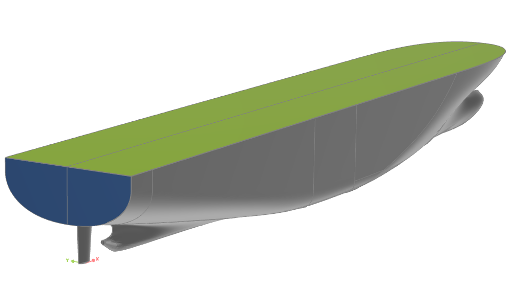
Build fully-parametric ship hulls using the component-based ship modeling workflow, covering main hull surfaces, transoms, decks, bulbous bows, and appendages.
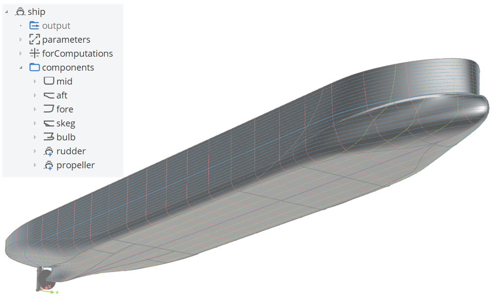
Component-Based Ship
A component-based ship, generated with the ship modeling workflow including a single skeg and bulb.
Planar Transom and Deck
Transom and deck surface modeling
Boat Hull Design
Model hard chine planing hulls with spray rails and propeller tunnels — from workflow-based generation to fully custom builds from scratch.
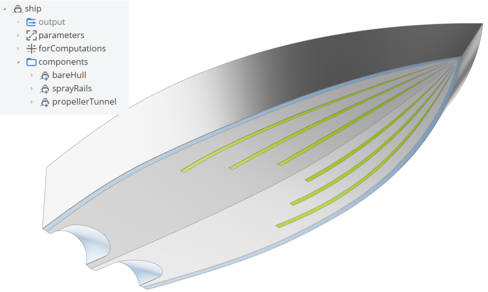
Hard Chine Boat Workflow
A component-based hard chine boat, generated with the hard chine ship modeling workflow including spray rails and propeller tunnels.
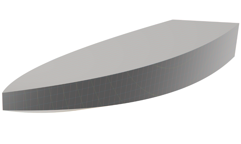
Hard Chine Boat (from Scratch)
A fully-parametric hard chine boat, built from scratch, with custom functions.
Shape Deformation and Morphing
Deform imported hull geometries without rebuilding: delta shift, Lackenby transformation, free-form deformation of a bulbous bow, and general mesh morphing for hull variants.
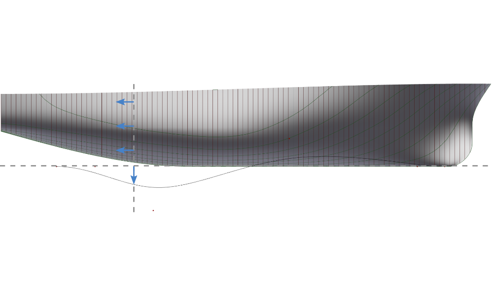
Hull Variation with Delta Shift
Morphing of existing hull using a delta shift
Generalized Lackenby Transformation
A Lackenby transformation to modify the hull form of a ship systematically by adjusting its sectional area curve
Deformation of an Imported Ship Hull
Morphing of various parts of an imported ship hull
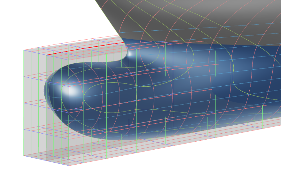
Free-Form Deformation of a Bulb
Free-Form Deformation used to modify a bulbous bow
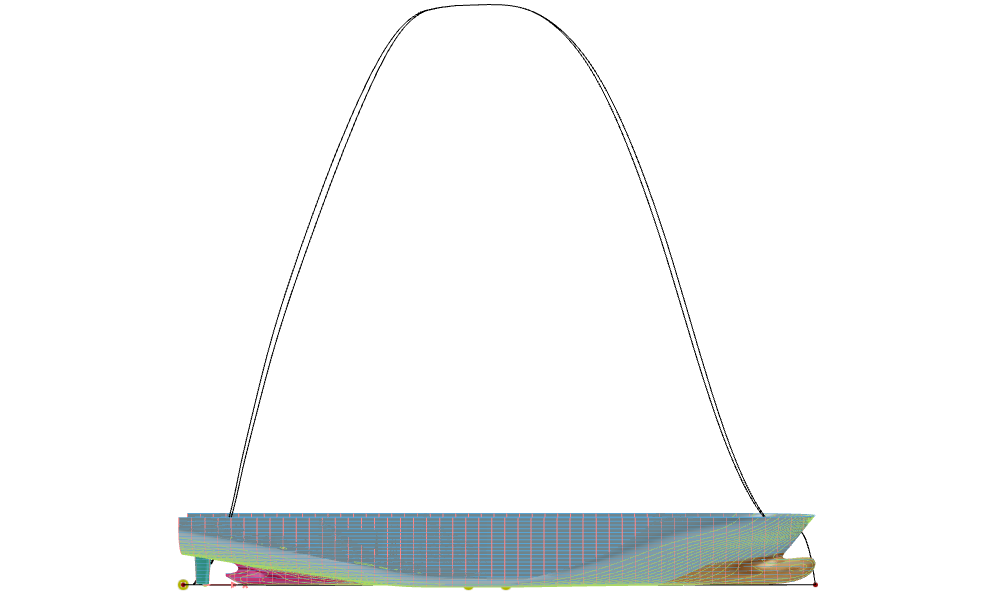
Hydrostatics
Calculate a ship's hydrostatic characteristics — displacement, metacentric height, and stability curves — directly within CAESES.
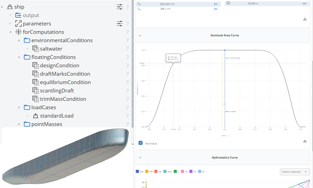
Hydrostatics
Learn how to calculate a ship's hydrostatic characteristics.
Powertrain
Model engine components for simulation-driven powertrain optimization: axis-symmetric piston bowls with automated compression ratio adjustment, and symmetric intake ports with cylinder heads and valves.
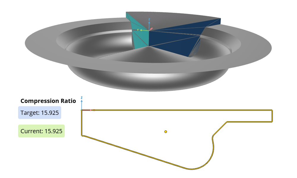
Piston Bowl Modeling
Axis-symmetric piston bowl, with automated compression ratio adjustment.
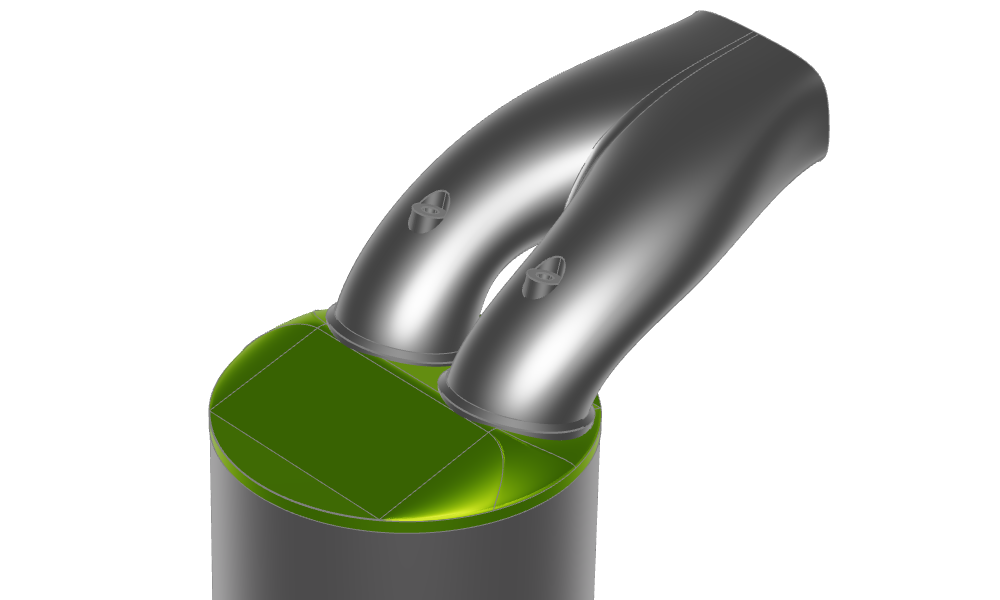
Intake Port Modeling
Symmetric intake port with cylinder head and valves.