Mesh Morphing in CAESES
The morphing capabilities of CAESES offer a flexible shape modification especially for imported geometry. The Mesh Morphing is a free form editing tool used on discrete STL geometries. Any standard geometry type that is compatible with CAESES can be used and modified, such as STEP, IGES, SAT, or also tessellated geometries in STL format. Note that the final morphed geometry will be a tessellated (discrete) description of the shape.
In this tutorial we will import an intake port as a STEP file and interactively modify certain regions of it.
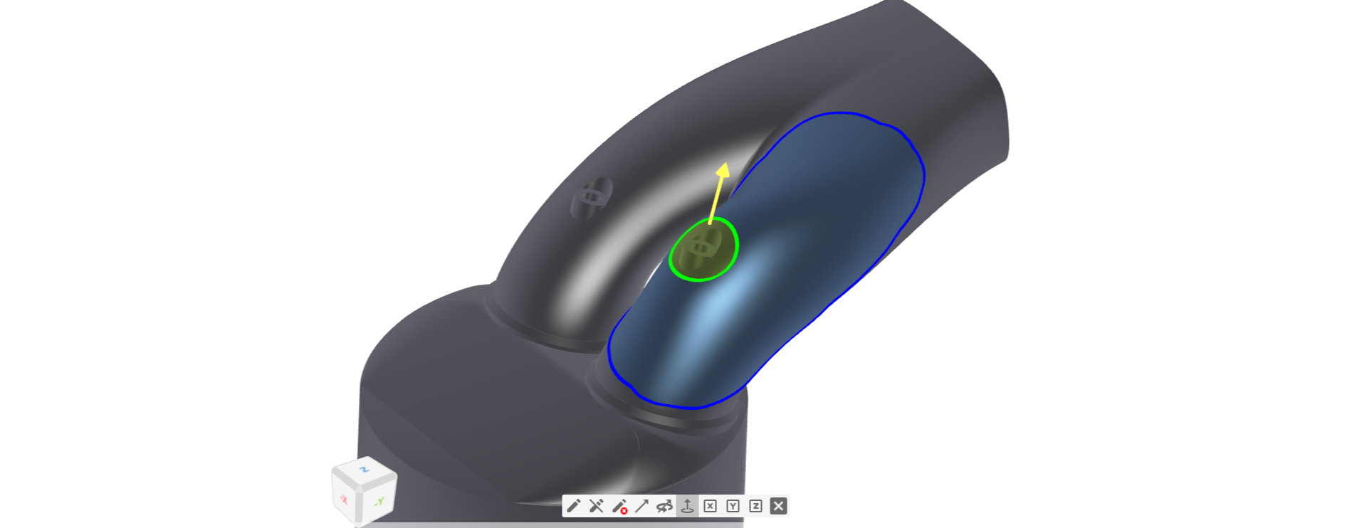
You can find more general information about RBF Morphing here.
Set Project Units
- Open a new CAESES project
- Save the project via Menu > File > Save Project As.
Let's set the units of the project. This is useful for file exchange (import and export), since the units are written in files like STEP, IGES or PARASOLID.
- In the File tab select the project node in the Object Tree:
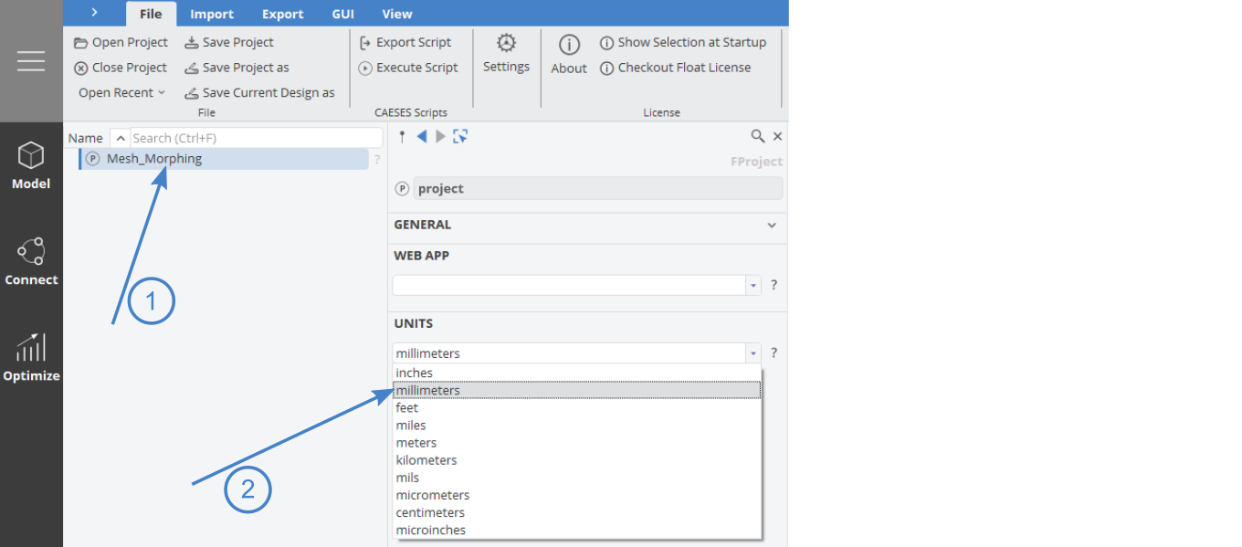
- Set the units to "millimeters".
Import Geometry
Let's get started by importing the intake port geometry in STEP format.
Download STEP- Go to the Menu workspace and switch to the Import tab.
- Choose STEP and locate the recently downloaded file intakeport.step
- Click Open to open/import the file into CAESES
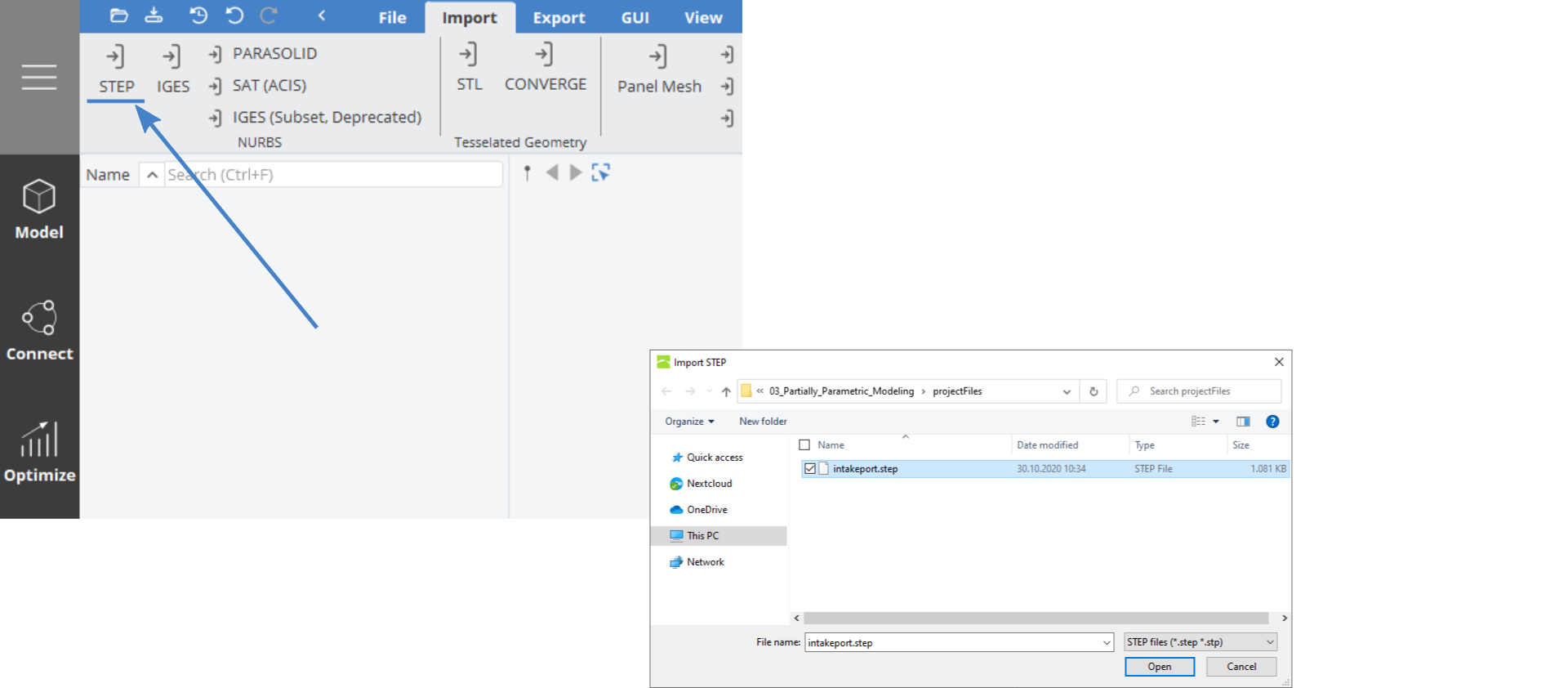
The imported geometry of the intake port should be visible in the 3D View now.
Morphing
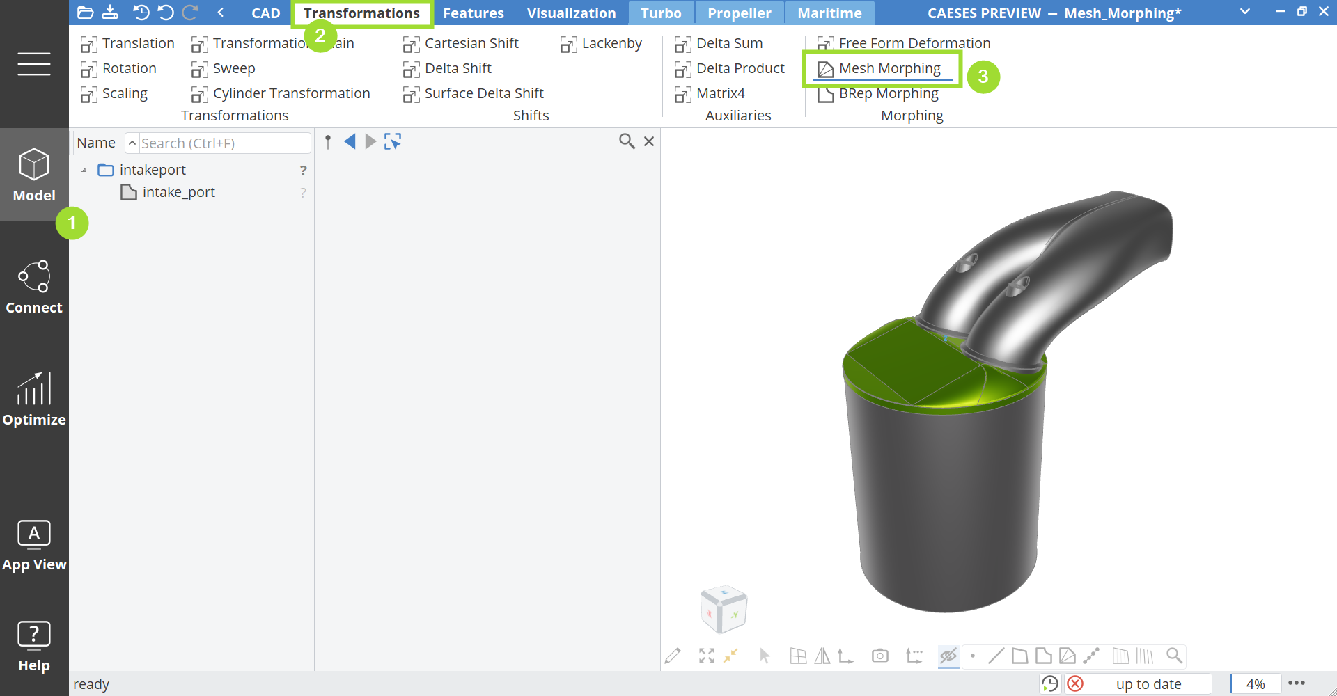
Now we will create a Mesh Morphing object.
- Switch to the Model workspace in the side bar (the CAD tab should be opened per default) and go to the Transformations tab
- Choose Morphing > Mesh to create a Mesh Morphing object and switch to the CAD tab
Set Input Geometry
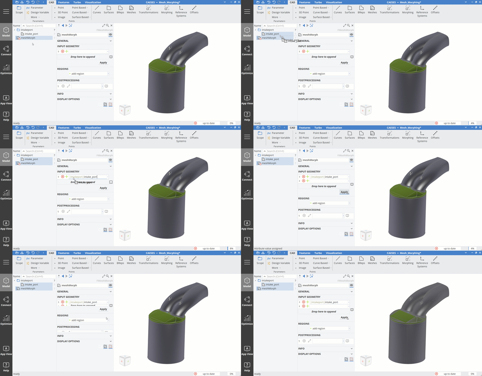
- Drag and drop the intake_port into the Input Geometry field of meshMorph.
- Press the Apply button. The mesh should be visible on the input geometry of the meshMorph object afterwards.
- Hide the scope intakeport by clicking on the scope icon to take a look at the meshMorph object only.
Do not forget to compile the input geometry (by clicking the Apply button) before adding a region. This creates the tessellation triangles for your input objects, which form the basis for the shape deformation.
Add a Deformation Region
In this step we will add a deformation region. An interactive painting tool is used to mark the area that should be deformed.
- Add a region in the meshMorph attribute Regions.
- Click Edit Region to switch to the edit mode.
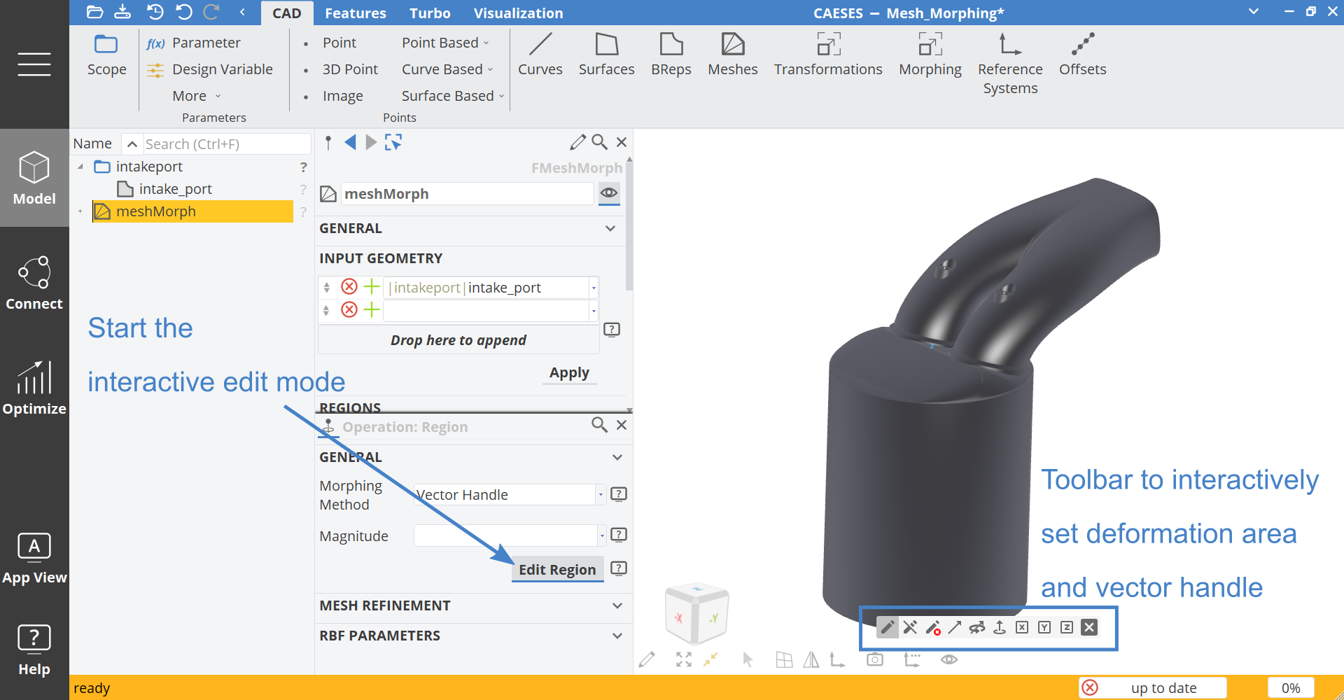
The yellow bar at the bottom of the window indicates the interactive edit mode.
In the 3D view a toolbar is displayed when you are in the Region edit mode. It provides the tools to mark the area that can be freely deformed, mark a rigid motion area and set a vector handle for the direction of the deformation.
Let's mark an area on the left side of the left port. The tool to mark the deformation area is pre-selected (pen icon on the left end) in the toolbar in the 3D View.

- Once you hover over the geometry a paint circle appears. To mark the area within the circle, click with the left mouse button. The geometry will be sprayed in blue, which indicates the deformation area.
- Change the size of the paint circle by holding Ctrl and scroll in or out with the middle mouse wheel.
Keep to left mouse button pressed and move the mouse over the geometry to mark and spray a larger area smoothly.
- Use the Delete Area tool if you accidentally marked a larger area than intended.

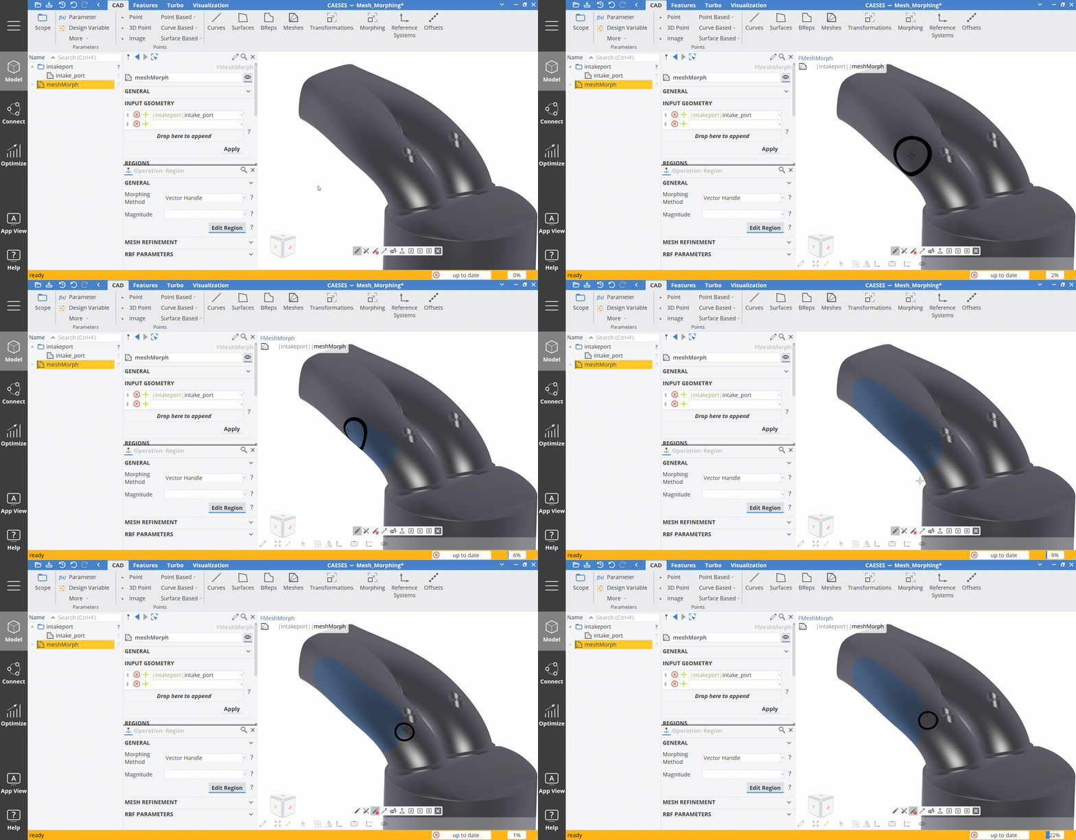
Once satisfied with the marked deformation area, we place the Vector Handle to determine the deformation direction.
- Choose the Place Handle tool from the toolbar.
- Place the handle on the blue deformation area.
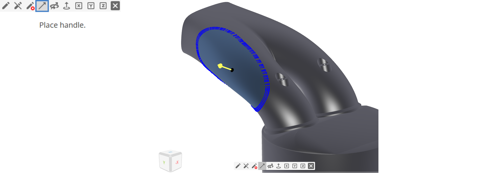
Initially the handle always points in normal direction.
- Choose the Rotate Handle tool to adjust the handle direction.
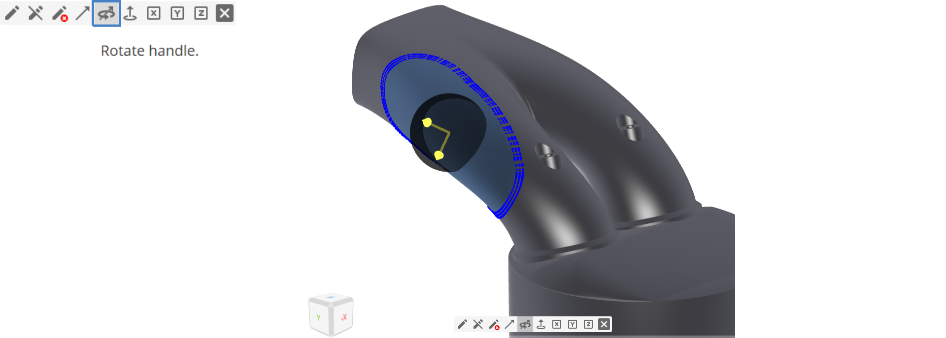
Now the deformation area and the vector handle are set up.
- Choose the Deform with Handle tool and interactively pull the handle or push it in.
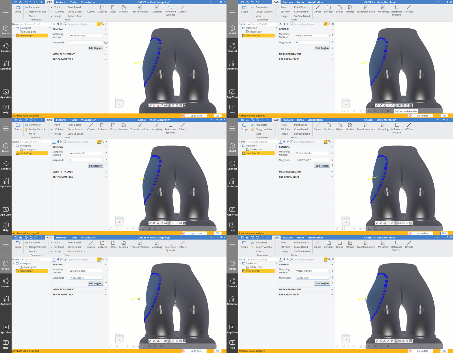
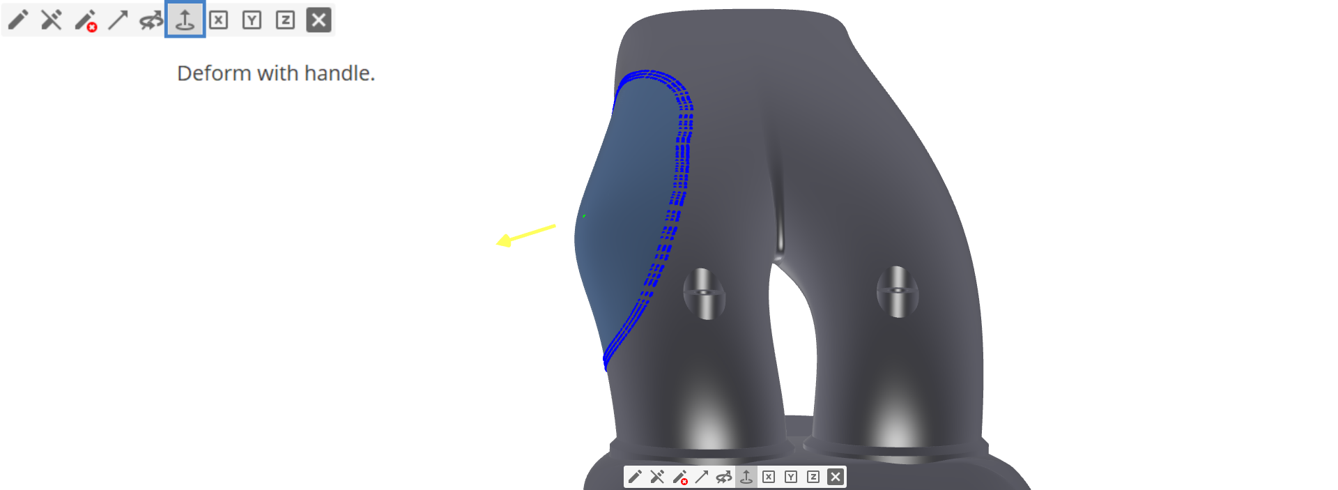
The magnitude of the Vector Handle will be automatically written in the Magnitude attribute field depending on the interactive movement of the vector in the 3D View.
If you set a Parameter or Design Variable for the Magnitude value, the Magnitude field will not be overwritten by the interactive movement of the vector anymore.
- Leave the edit mode by pressing Esc or Enter
Add another Deformation Region with Rigid Motion Area
In this step we will create another region and include a Rigid Motion Area. This allows us to keep certain parts unchanged, while moving them in 3D space. In order to shift the valve seat, we will create a deformation area (blue) and add a rigid motion area (green). The valve seat in this example shall not be deformed while moving.
- Create another Region in the meshMorph object by choosing add new operation in the Regions attribute
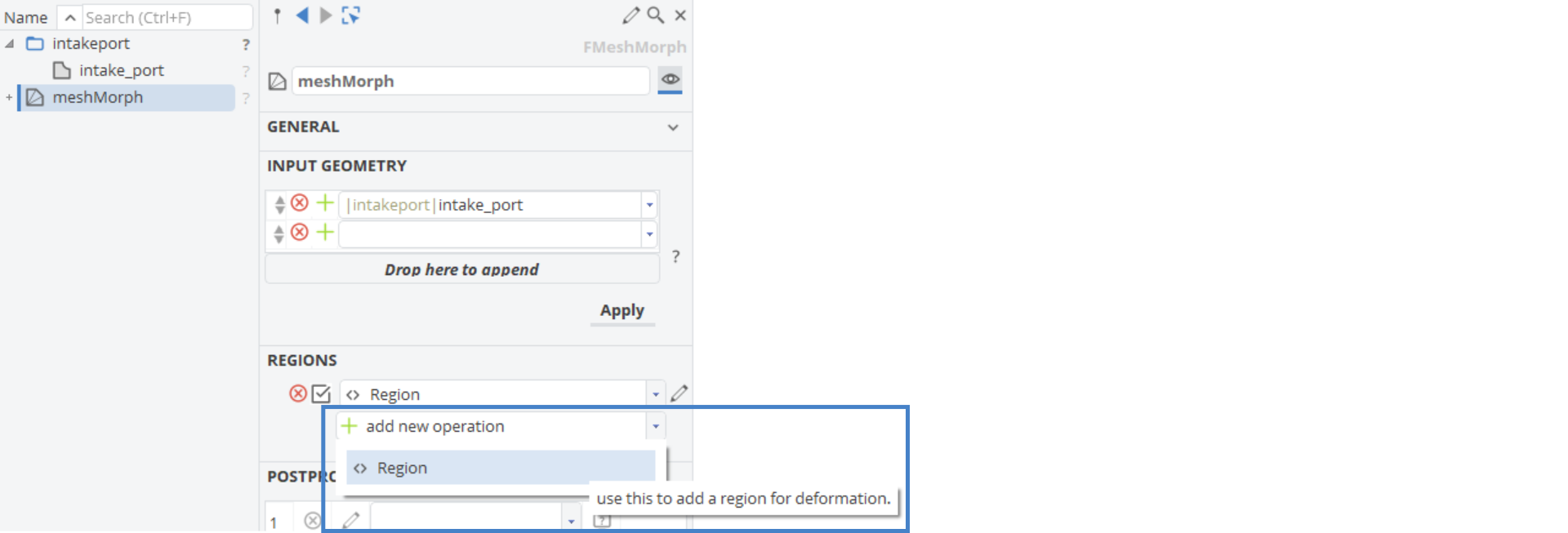
- Start the edit mode by clicking Edit Region
- Mark the right port around the right valve seat with the deformation area tool (blue spray color). Just like we did in the previous step.
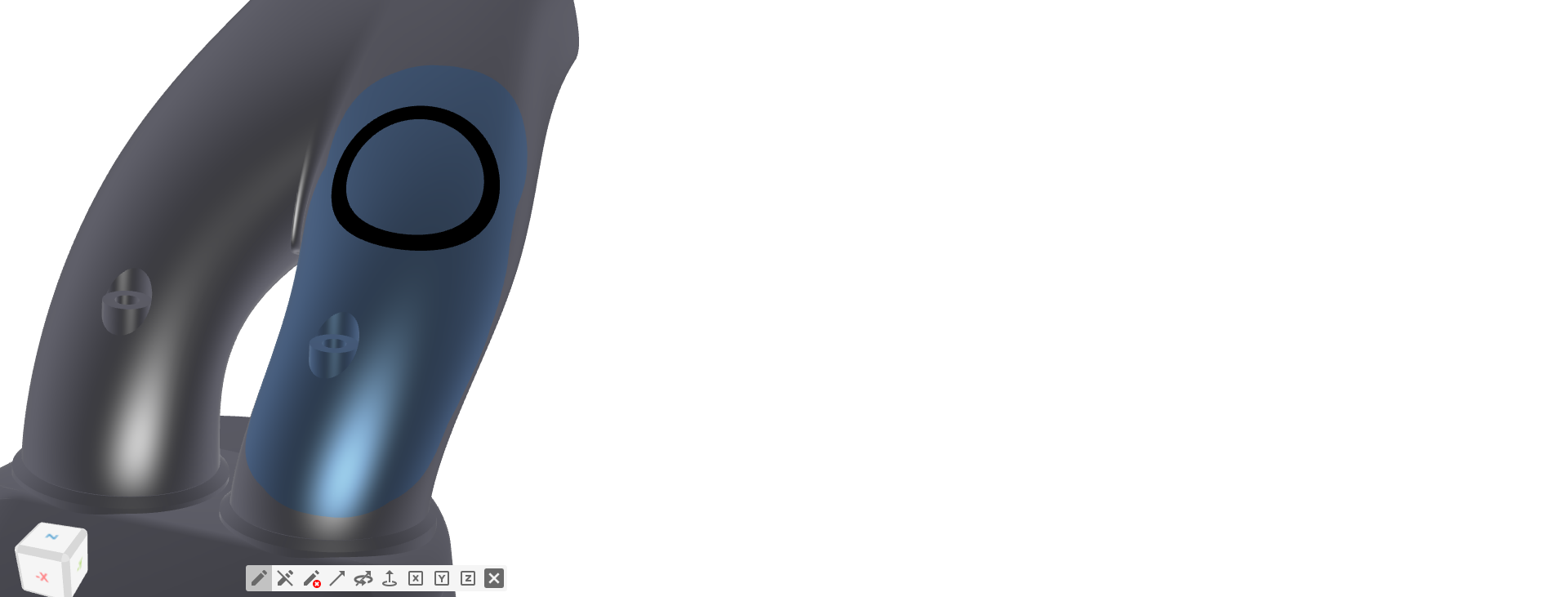
- Select the Mark rigid motion area tool in the toolbar

- Adjust the size of the circle by holding Ctrl and scroll with the mouse wheel until the diameter is as small as the valve seat.
- Mark the valve seat as a rigid motion area, which will be colored in green.
- Place the Vector Handle on the Rigid Motion Area (green), facing in normal direction of the upper valve seat area.
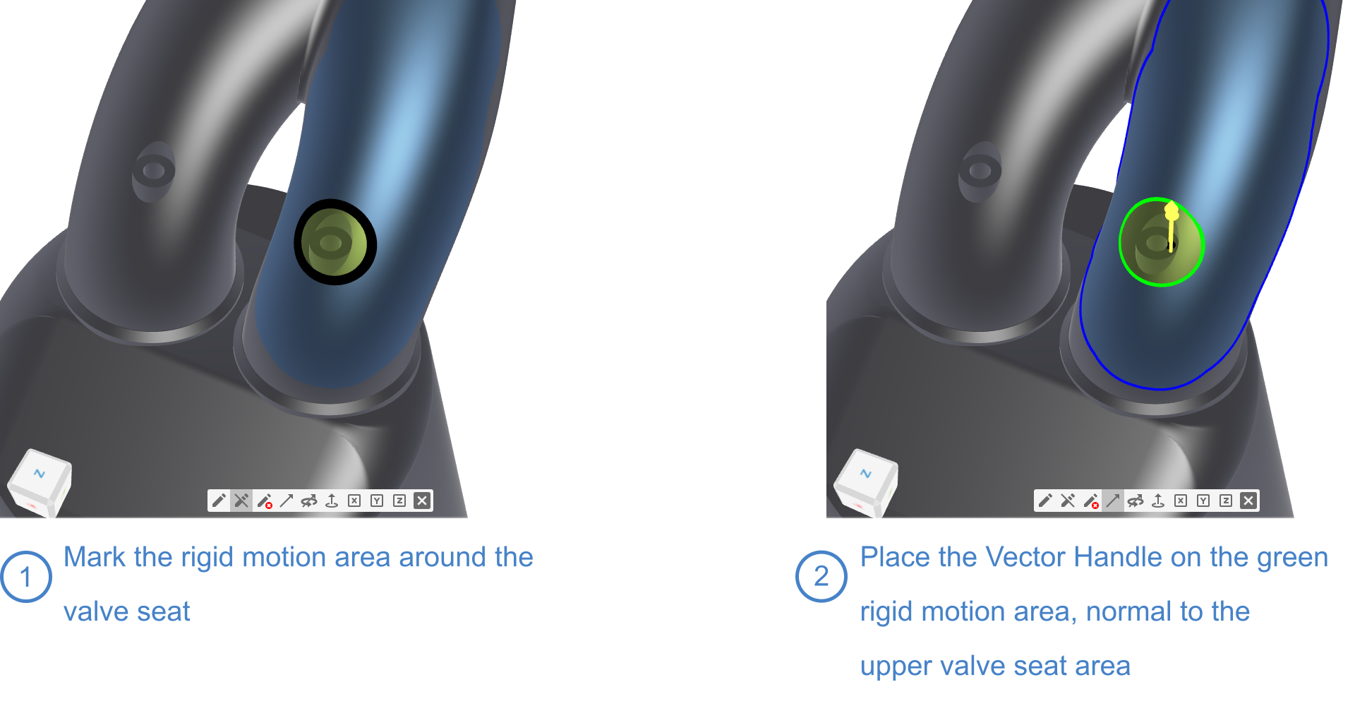
- Switch to the Deform with handle tool and see what happens when you pull the Vector Handle up in positive Z-direction
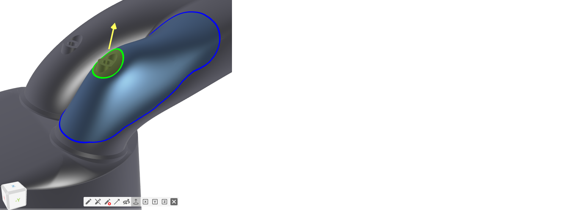
This time the green colored area is not modified, but rather shifted, while maintaining its rigid form. The modification is applied to the blue deformation area, that allows shifting the valve seat up.
- Let's leave the edit mode by pressing Esc or Enter
Create Design Variables
Design Variable for Region 1
In order to make a partially-parametric model, we introduce a couple of Design Variables for our Mesh Morphing deformations.
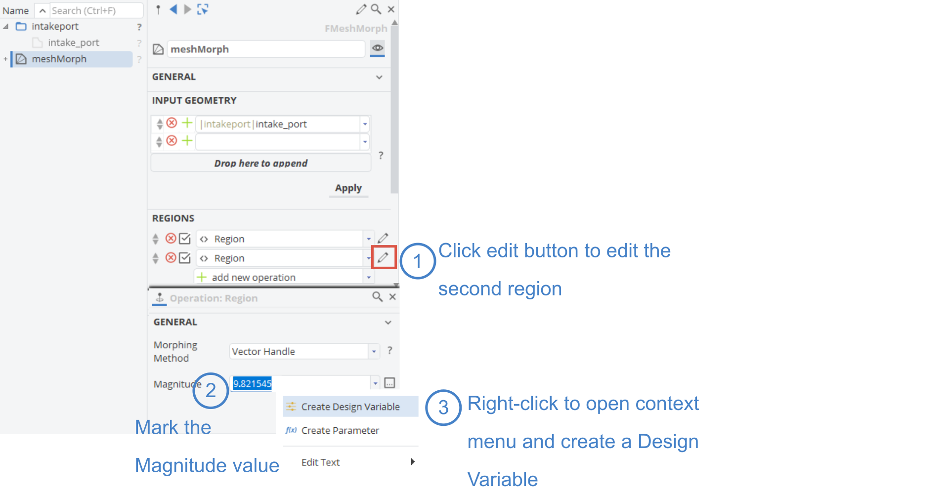
- Open the settings for the first region by clicking the edit button (pen) next to it
- Mark the value in the Magnitude attribute
- Click the right mouse button and create a Design Variable from the context menu
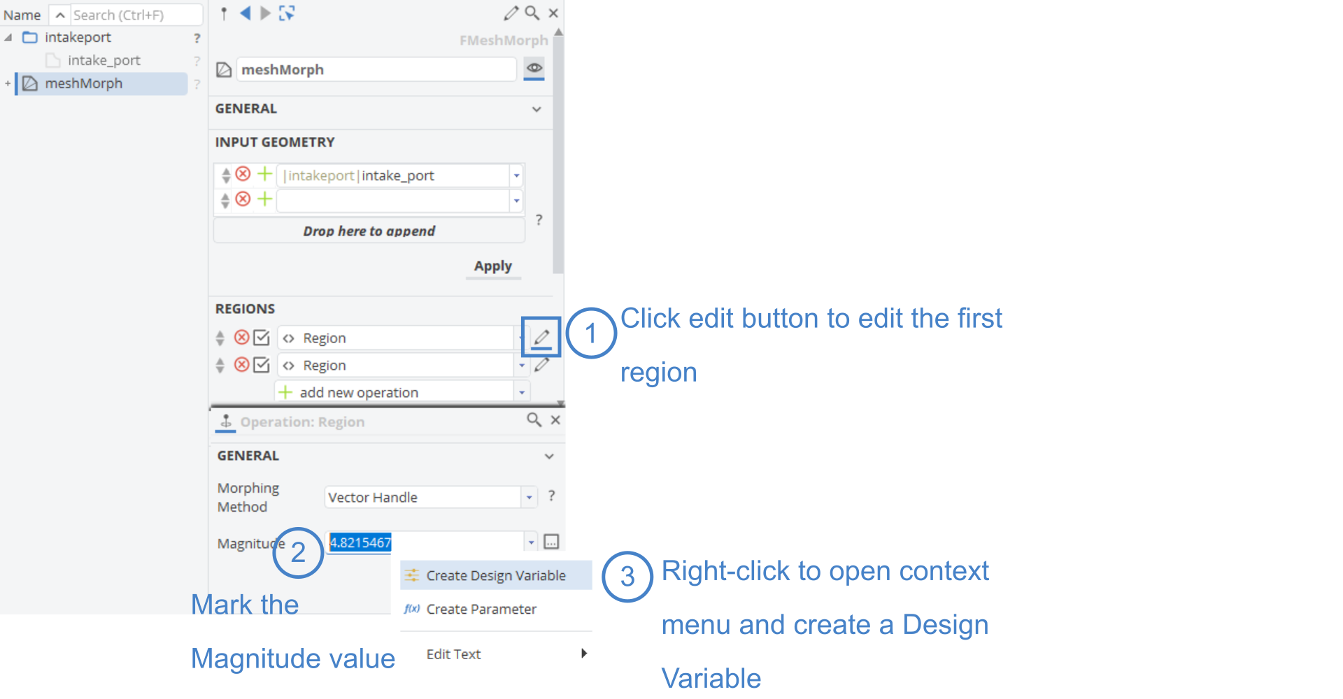
- Change the name of the Design Variable from parameter1 to "Magnitude_Region1"
- Click the edit button next to the Design Variable Value
- Set the Default Value to
0 - Set the Lower Bound to
-5 - Set the Upper Bound to
5
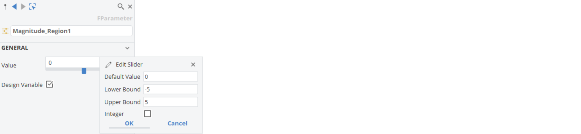
- Move the slider and watch how the first Deformation Region will be modified accordingly.
Design Variable for Region 2
Now, we want to introduce a second Design Variable that defines the upwards or downwards shift of our valve seat for the second region we set up.
- Repeat the previous step but this time open the settings of the second region with the edit button next to it
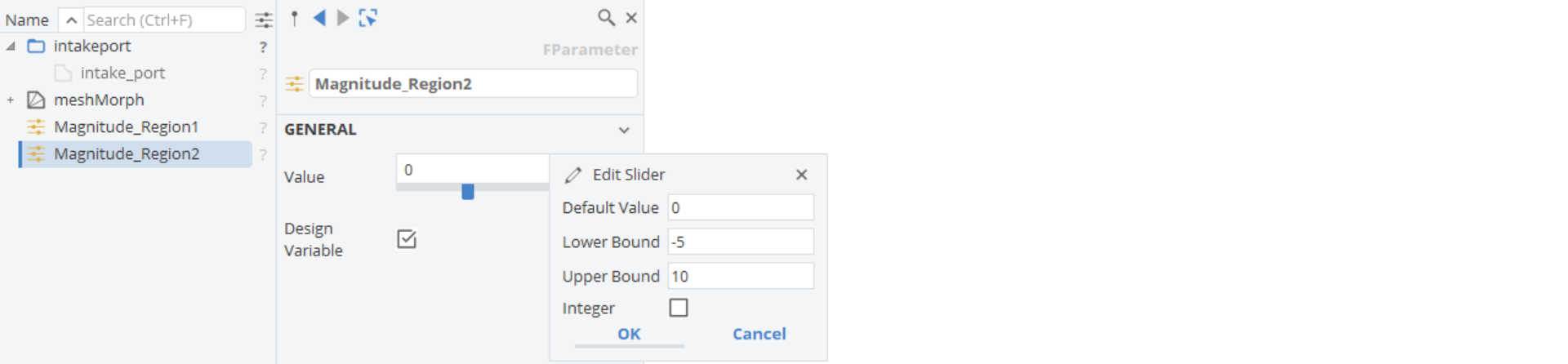
- Change the name of the Design Variable from parameter1 to "Magnitude_Region2"
- Click the edit button next to the Design Variable Value
- Set the Default Value to
0 - Set the Lower Bound to
-5 - Set the Upper Bound to
5 - To hide the input geometry click the icon in the object tree in front intake_port (the icon is greyed out when the object is set invisible in the 3D View)
- Click on the grey Design Variable icon to see all Design Variables in the Object Editor at once
- Play with the sliders of the Design Variables and see how the two deformation areas are changed

Export Modified Shape as STL
To finalize this tutorial we will export our modified morphed geometry in the STL format.
The final modified geometry is always a tessellated (discrete) description of the shape when deformed with the mesh morphing technique.
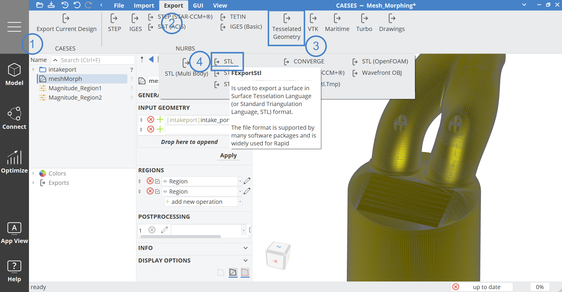
- Set the sliders to a desired value
- Select the meshMorph in the Object Tree
- While meshMorph is selected go to the Menu workspace > Export tab > Tessellated Geometry > STL to export the current shape.
CAESES Project File
If you want to take a look at the finalized parametric model you can find the resulting CAESES project file mesh-morphing.cdb here: