Hydrostatics
In this tutorial, we will explore CAESES functionality to calculate a ship's hydrostatic characteristics. First, we will introduce the fundamental workflow and configurations and apply them to a sample ship. For an in-depth explanation about the physical principles, please refer to the Hydrostatics Documentation.

The starting point for this tutorial is the default component-based Ship without a bulb, skeg, rudder or propeller. However, the hydrostatics workflow is the same for the other ship types.
Floating Conditions
In CAESES, a floating condition precisely defines the ship’s draft, trim, and heel. You can define a floating condition in one of the following ways:
- Prescribing the draft, trim, and heel directly.
- Specifying the ship’s mass and center of gravity to automatically compute the equilibrium floating condition.
- Using trim and mass center of gravity values, which have no effect once the floating condition is evaluated.
- Defining draft marks by specifying two longitudinal positions and the corresponding drafts at those positions.
In all cases, an Environmental Condition must be assigned to the Floating Condition. By default, when a Ship Object is created, this is set to a saltwater condition.
Floating conditions placed in the Ship Object editor are considered when evaluating the hydrostatics of the ship. To create a new floating condition and automatically assign it to the selected ship, use the Create New button below the object list.

After clicking Create New, a new FloatingCondition object is created. All available options are shown below.

Before we dive into creating, configuring and evaluating floating conditions, let's have a look at the predefined Design Condition first.
Design Floating Condition
The Design Condition is automatically created when creating the Hull Parameters in the ship object. It's always called "designCondition" and additionally a complementary Environmental Condition with presets for saltwater are automatically created. You can find them in the forComputations scope within your ship component:

The Design Condition is a special kind of prescribed floating condition that always uses the design draft defined in the Hull Parameters. Please don't manually change this value. If you want to modify the design draft, adjust it within the Hull Parameters instead of manually changing this value. Every component-based ship should always have a design condition set.
If you want to calculate the hydrostatics for a custom ship, you can use our Generic Ship Component as a wrapper for your geometry.
Now, let's have a look at the ships hydrostatics for our design scenario!
Hydrostatics Viewer
To visualize and navigate the hydrostatic characteristics of your ship, you can use the built-in Hydrostatics Viewer.
- First you have to create and set up the Hydrostatics object from the Maritime tab.
- Select the ship you want to analyze - either via drag and drop, or the dropdown menu of this input field.
- Finally, click on "Show Hydrostatics" to open the Hydrostatics Viewer.


You can set the reference length for the Hydrostatics to either Length between perpendiculars (LPP), Length on the waterline (LWL), or Length overall (LOA).
The hydrostatics viewer is used to navigate through all defined floating conditions on your ship. By default, the first tab is your ship's Design Condition. Each condition has a small header, briefly describing the displayed condition. Below the header, you'll find three sections which can be expanded by clicking on them.
Depending on the selected floating condition, the available sections in the hydrostatics viewer vary.
For prescribed, trim–mass and draft marks floating conditions, the sections Main Dimensions, Sectional Area Curve and Hydrostatics Curve are available.
For equilibrium floating conditions, the sections Main Dimensions, Sectional Area Curve and Righting Lever Curve are shown.
Since we haven't added any additional floating conditions to our ship yet, we can only see the Design Condition so far.

Next, we will create an additional floating condition for our ship.
Adding a Prescribed Floating Condition
To create a new floating condition, we can use the button in the For Computations section of the ship object editor. You can also see, which floating conditions are being considered in the hydrostatics:
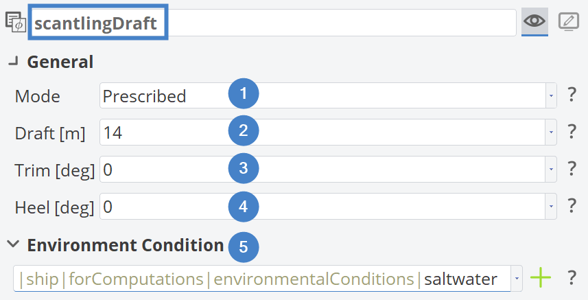
In this tutorial, we will create a prescribed floating condition for the ship’s scantling draft. The scantling draft is set to 14 meters on an even keel, i.e., with zero trim and zero heel. You can assign a custom name to the floating condition to make it easier to identify later.
To configure a prescribed floating condition, set the Mode to Prescribed (1) and enter the values for Draft (2), Trim (3), and Heel (4) in the corresponding fields. For the Environmental Condition, the automatically created saltwater condition is reused (5).
It's also possible to use parameters or design variables for draft (2), trim (3) and heel (4).
Main Dimensions
After we've entered all values, we can have a look at the Hydrostatics Viewer to the right and you'll see a new tab, indicating that our ship now has a second floating condition. Clicking on the tab reveals the header with a brief description of the floating condition and the main dimensions has all values calculated for our scantling draft.
The length between perpendiculars LPP is defined for the Design Condition! This value will not change with floating conditions and can be used as a reference. For more information have a look at the Main Dimension Documentation.
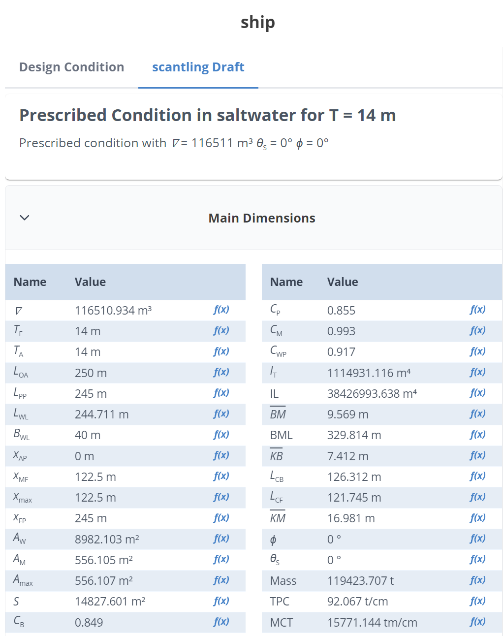
To use these values inside of our project, we can create parameters for any main dimension by clicking on the f(x) parameter button.
Please note, that the parameters reference floating conditions by name. Changing the name of a floating condition will break the parameters.
Furthermore, you have the option to export all the values to *.csv or *.xlsx by clicking the save button in the lower right corner.
Sectional Area Curve
Below the main dimensions you can find the Sectional Area Curve. Its values are made non-dimensional for easier comparison to other ships. For more detailed information about the SAC, check out its Documentation.
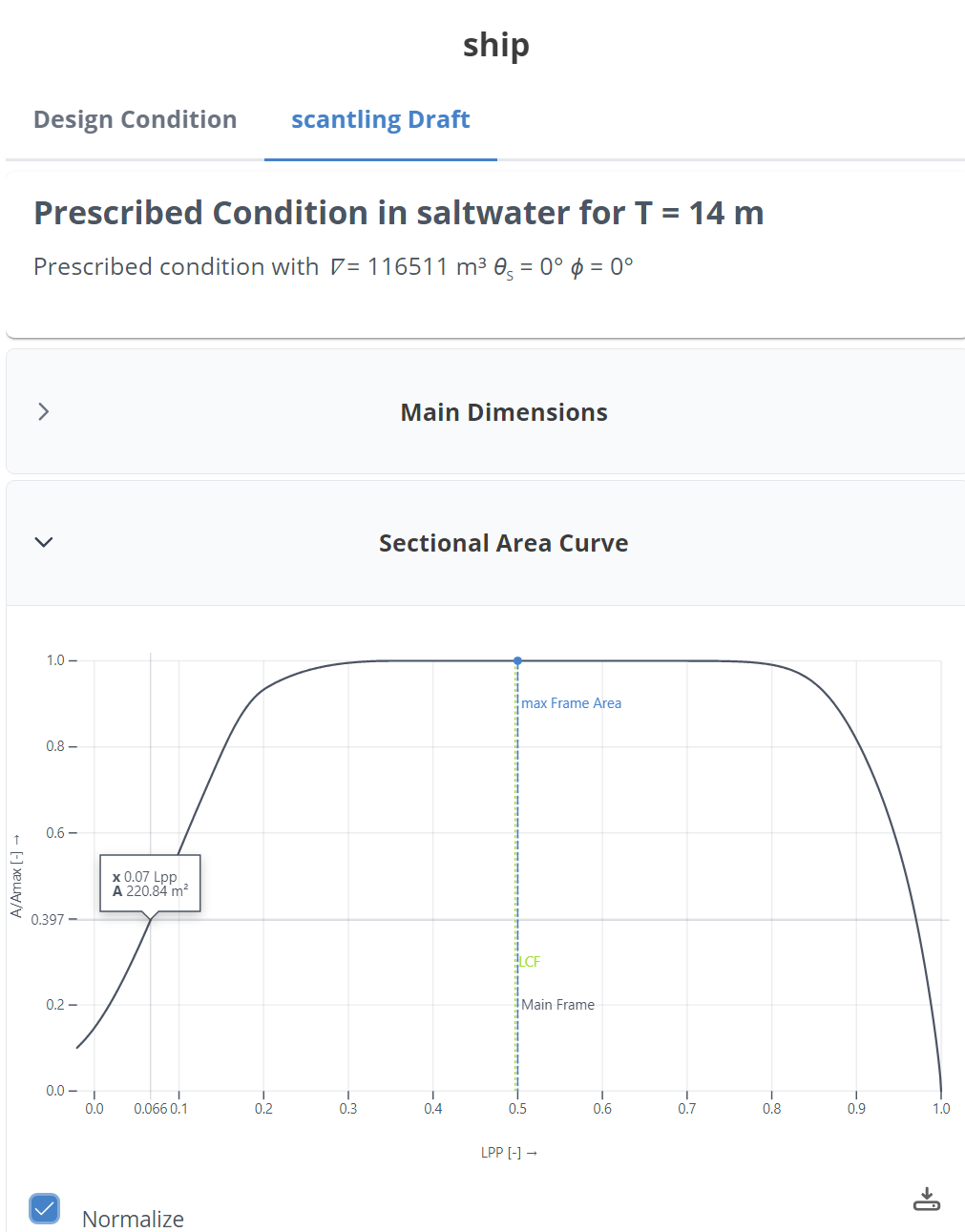
Similar to the Main Dimensions, you can export the SAC to *.csv or *.xlsx to get the point data or to *.svg to save the image.
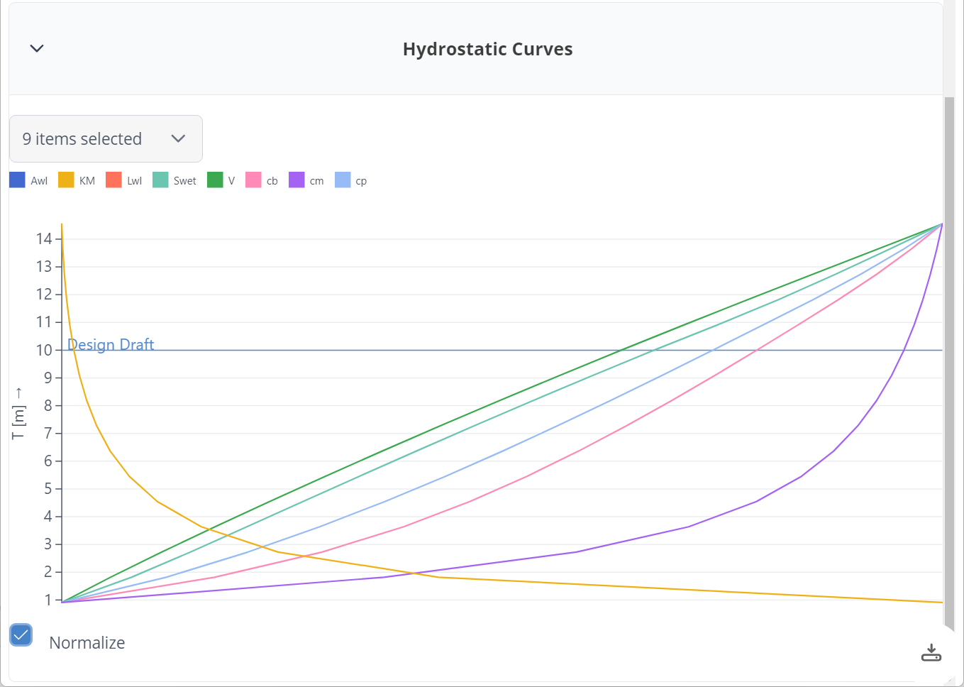
Hydrostatics Curve
Additionally, you can view Hydrostatics Curves for the floating condition to evaluate your hull form for a series of drafts. Since the computation is not instantaneous, you have to opt-in to this feature. Similar to the sectional area curve, the values are made non-dimensional and you can export the values to *.csv, *.xlsx or *.svg.
Now you've got a good understanding of our hull hydrostatics. Next, we also want to investigate its intact stability. For this, we need an equilibrium floating condition.
Adding an Equilibrium Floating Condition
The setup of an equilibrium floating condition is similar to a prescribed floating condition. As before, you create a new floating condition through the editor of our ship object by clicking the Create New button underneath the objectlist for the floating conditions.
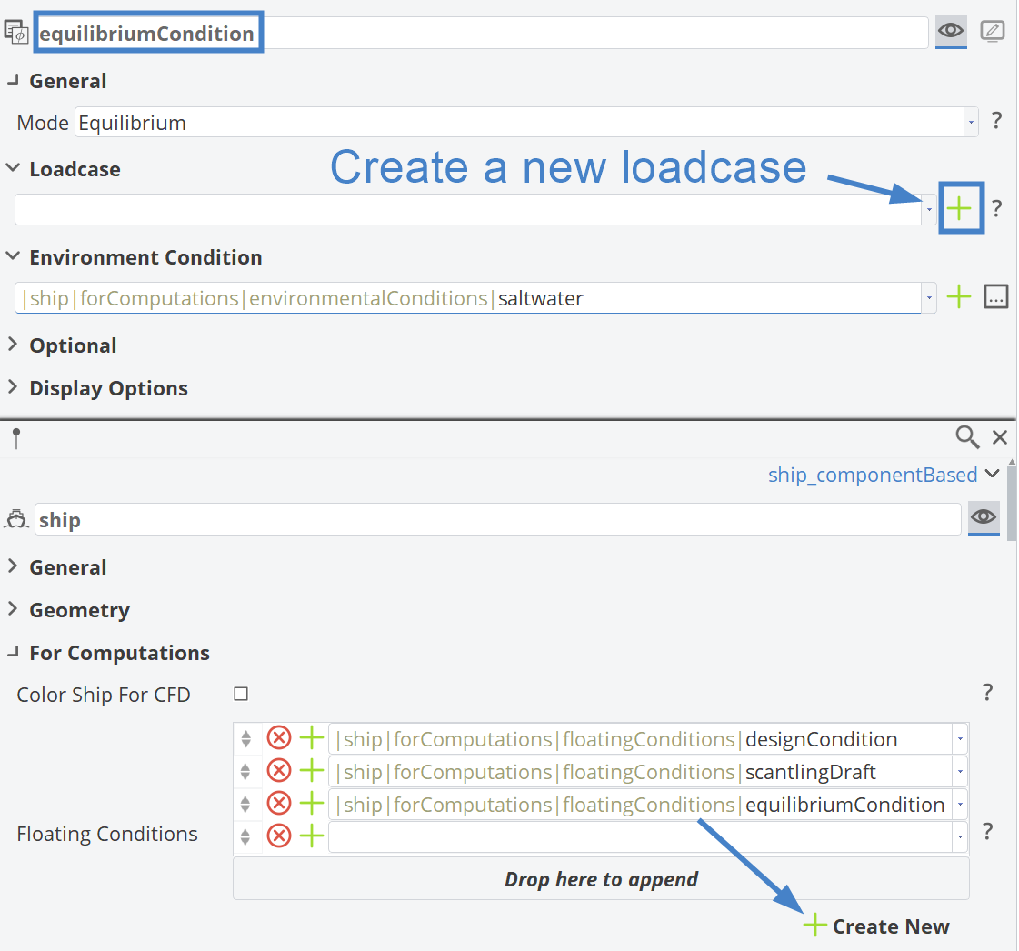
In our example, we've renamed the new floating condition to "equilibriumCondition" and selected our known saltwater environmental condition. Next, we need to specify the Loadcase for this floating condition. Use the + button next to the input field to create a new loadcase. A loadcase collects an arbitrary number of point masses and calculates the resulting total mass and center of gravity. Take a look at the hydrostatics fundamentals for more information. Let's create a new loadcase, give it the name standardLoad and add two point masses to this loadcase. In our example, we've used these two point masses:
| Name | Mass [t] | center Point |
|---|---|---|
| Lightship | 30000 | [120, 0, 8] |
| Cargo | 50000 | [122, 0, 22] |
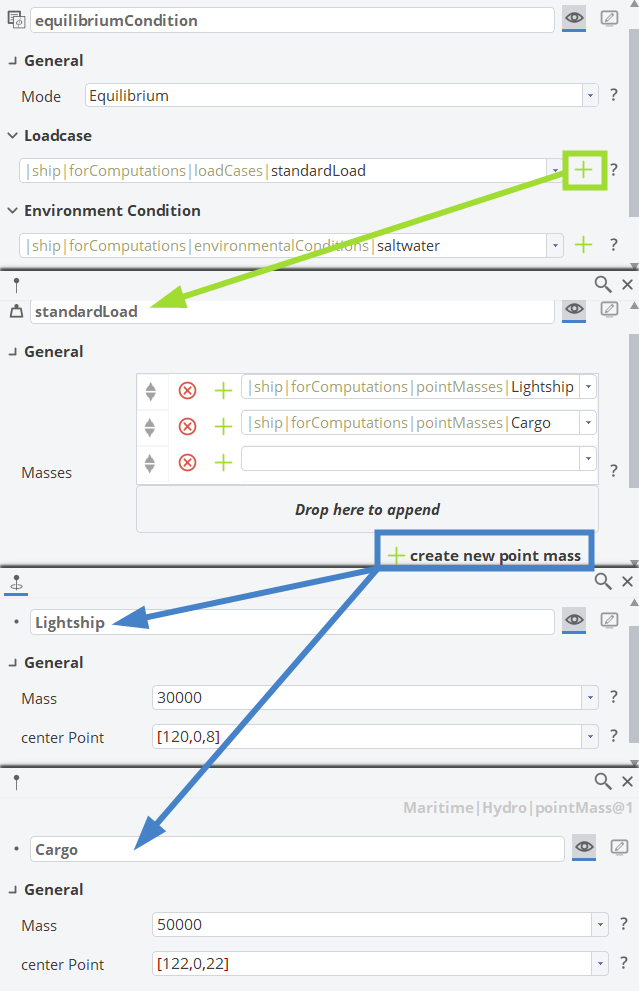
You can see, that the total mass of our ship is 80000 t and its center of mass is located at [121.25, 0, 16.75]. Switching back to the Hydrostatics Viewer, a new Tab with the Equilibrium Condition appeared, which has the option to calculate the Righting Lever Curve. The generation has to be manually triggered by clicking on the button Add Righting Lever Curve.
Intact Stability
After a brief computation, you will find the GZ curve or Righting Lever Curve displayed. Below the figure, a table with the IMO Intact Stability criteria 2.2.1 to 2.2.4 are being evaluated. Clicking on a table row will highlight the corresponding criterion in the viewer. You can create parameters and constraints for the criteria by clicking the respective buttons, just like in the main dimensions table.
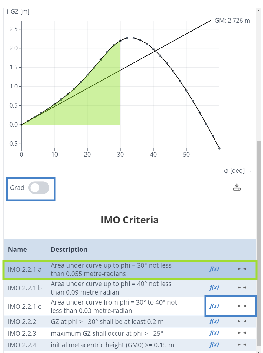
You can set the horizontal axis of the GZ curve or Righting Lever Curve to degrees or gradients by toggling the corresponding button.
Adding a Trim and Mass Condition
5.4.0This functionality requires CAESES version 5.4.0 or later.Setting up a Trim and Mass floating condition requires a trim value specified in degrees. As before, you can create a new floating condition through the Ship Object editor by clicking the Create New button below the floating condition object list.
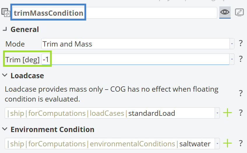
In CAESES, negative trim angles (in degrees) result in trim by the stern, while positive trim angles result in trim by the bow.
Adding a Draft Marks Condition
5.4.0This functionality requires CAESES version 5.4.0 or later.Setting up a Draft Marks floating condition requires specifying two draft values at two different longitudinal positions. As before, you can create a new floating condition through the Ship Object editor by clicking the Create New button below the floating condition object list.
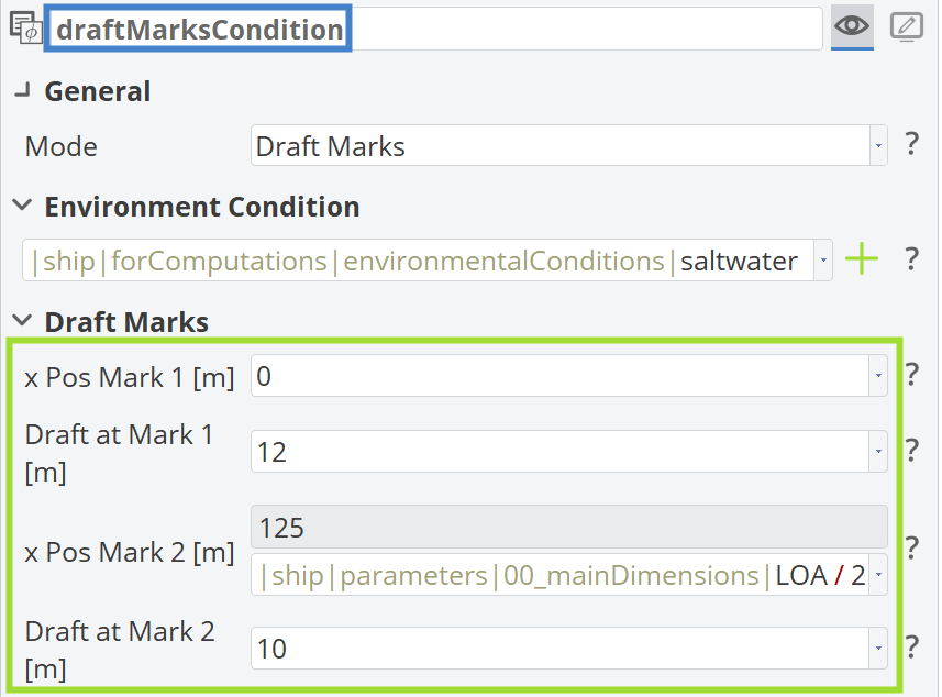
For improved hydrodynamic performance, ships are typically more submerged at the aft (i.e., a higher draft at the aft compared to the fore), indicating trim by the stern.
CAESES Project File
If you want to take a look at the finalized hydrostatics setup you can find the resulting CAESES project file hydrostatics.cdb here: