Piston Bowl Modeling
This tutorial gives you an overview on how to model piston bowls in CAESES.
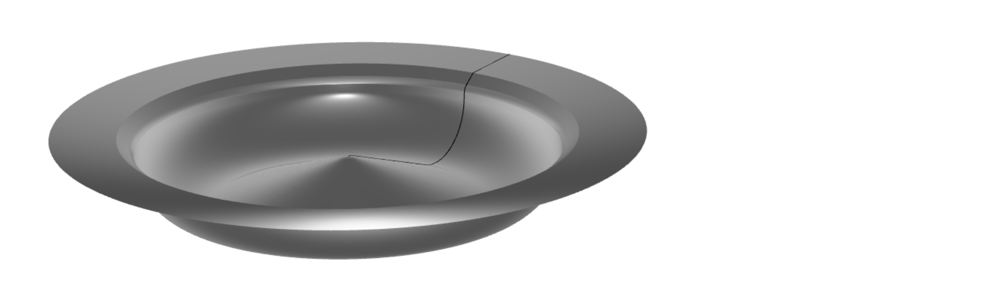
The workflow is typically divided into the following main steps:
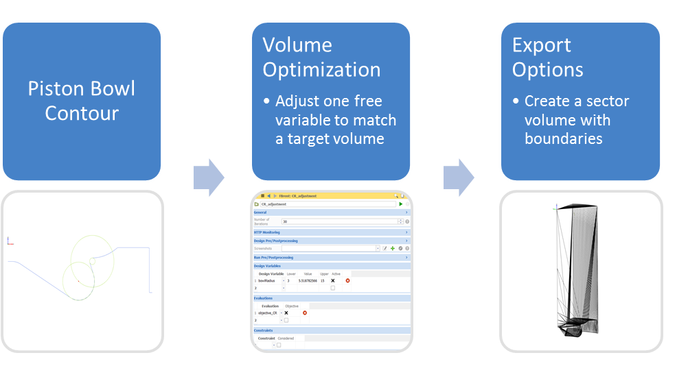
Piston Bowl Contour
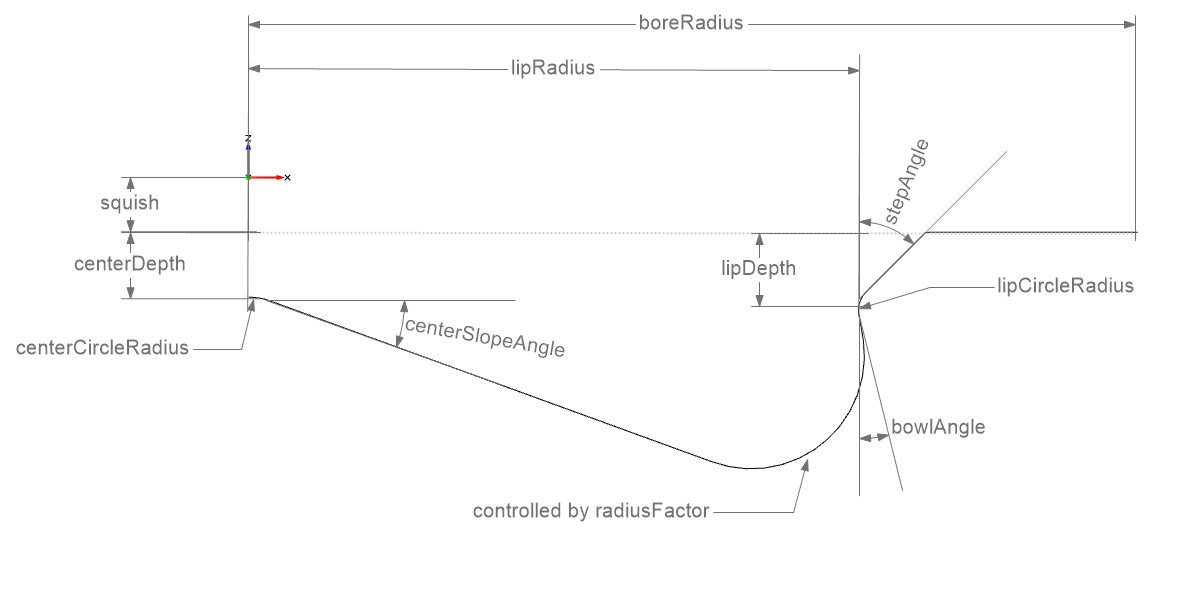
We assume that we create the sketch of the bowl contour in the X,Z-plane, so that X corresponds to the radius and Z to the direction of the movement of the piston. Note that we usually model things in millimeters.
Main Dimensions
Let's introduce some main dimensions, which we will need in later steps.
- Create a scope via Model > CAD > Scope and set the name to "01_mainDimensions" and make it your working scope.
- Create the parameters:
- boreRadius:
68.5 - CR:
15.925 - numberOfNozzles:
6 - squish:
4.221 - stroke:
165.1
- boreRadius:
Center
We will start modeling from the center. Here we create a circle with a certain start angle to define the slope angle. Create parameters for centerDepth(5), centerCircleRadius(5) and slopeAngle(20), the parameter values are shown in parentheses.
- Create a scope via Model > CAD > Scope and set the name to "02_center" and make it your working scope.
- Create the Design Variables:
- centerDepth:
5 - centerCircleRadius:
5 - slopeAngle:
20
- centerDepth:
- Create a circle in a plane via Model > CAD > Curves > Arcs > Ellipse based on a Center and Plane and set the name to centerCircle.
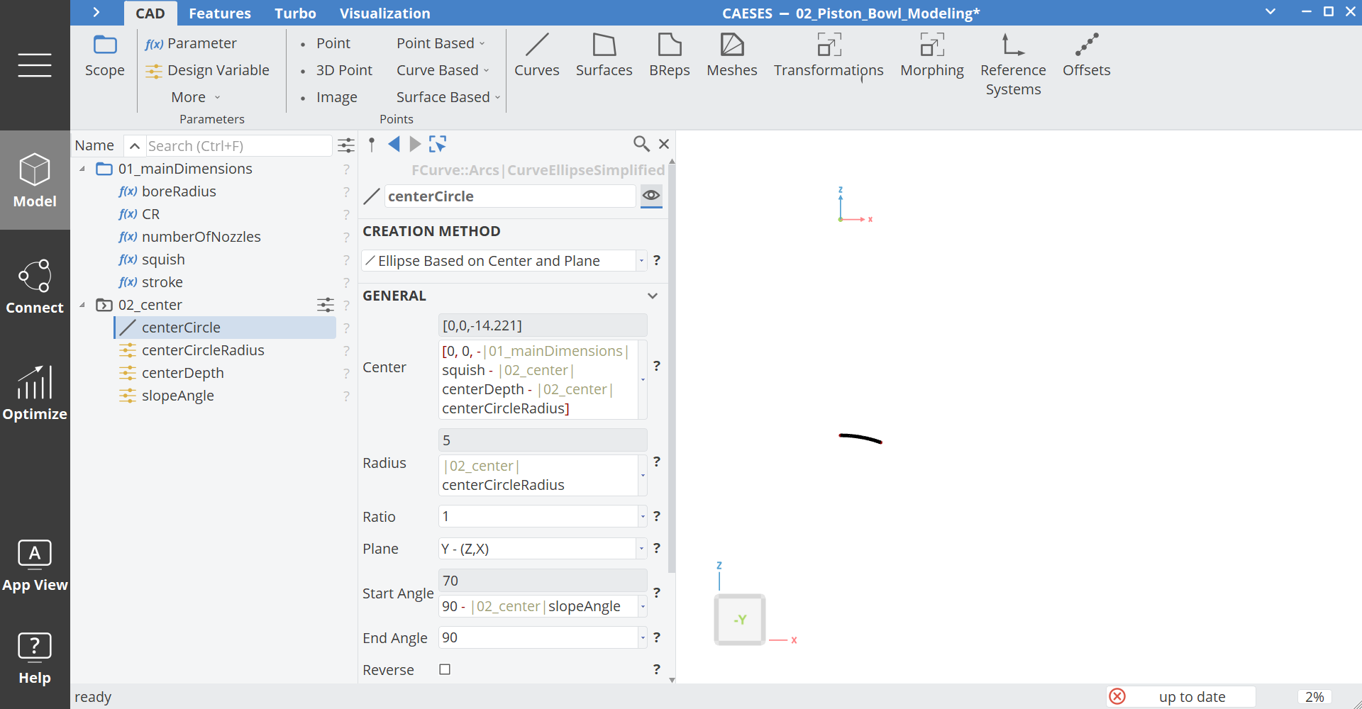
Set the arguments of the circle as (the paths of the parameter are not shown completely in the following expressions):
- Center:
[0,0,-squish-centerDepth-centerCircleRadius] - Radius: centerCircleRadius
- Plane: Y - (Z,X)
- Start Angle:
90- centerSlopeAngle - End Angle:
90
Slope
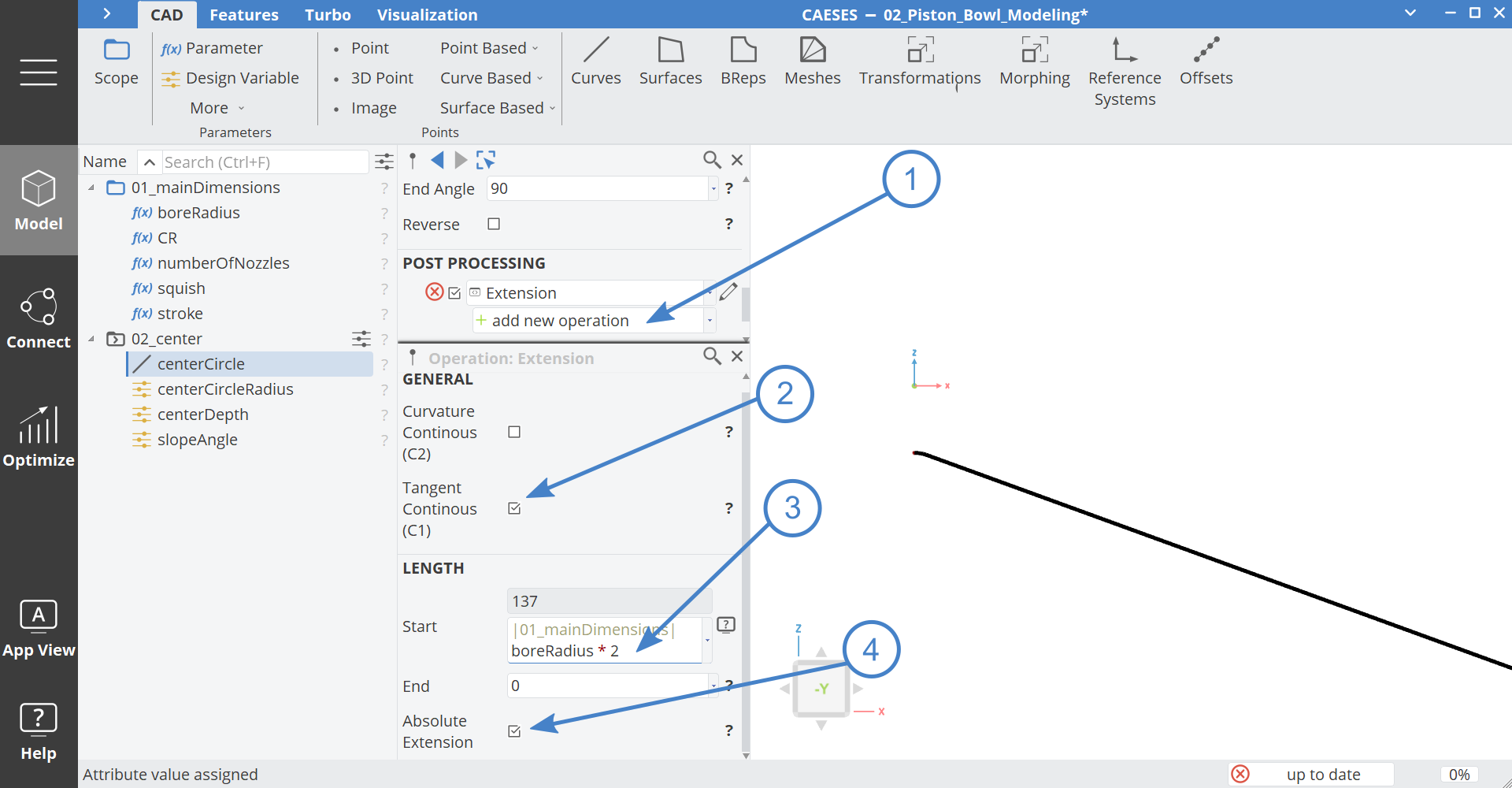
In order to create a linear slope, we can simply extend centerCircle:
- Select the curve centerCircle
- Add a new Post Processing Operation via add new operation > More > Extension.
- Activate Tangent Continuous.
- Set the start value to
boreRadius*2. - Activate Absolute Extension.
Lip Circle
For this bowl contour topology a key feature is the lip where the spray impinges the bowl.
-
Create a scope via Model > CAD > Scope and set the name to "03_lip" and make it your working scope.
-
Create the Design Variable:
- lipCircleRadius:
2 - lipRadius:
45 - lipDepth:
6 - bowlAngle:
10 - stepAngle:
45
- lipCircleRadius:
-
Create a circle in a plane via Model > CAD > Curves > Arcs > Ellipse based on a Center and Plane and set the name to lipCircle.
- Center:
[lipRadius+LipCircleRadius,0,-LipDepth-Squish] - Radius:
lipCircleRadius - Plane:
Y - (Z,X) - Start Angle:
180 - stepAngle - End Angle:
180 + bowlAngle
- Center:
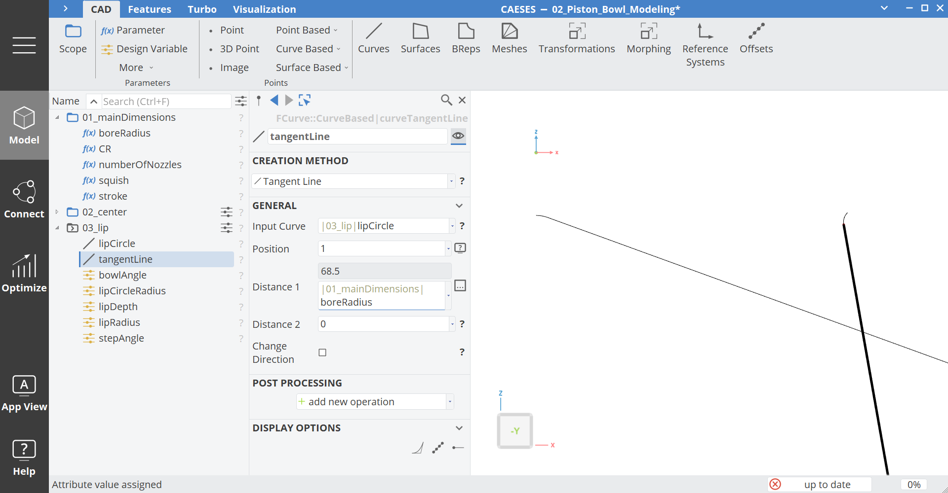
Now let's create a line which is tangential to the lipCircle on the bowl side.
- Create a line via Model > CAD > Curves > Curve Based > Tangent Line and set the name to "tangentLine".
- Set the Position to
1and the Distance 1 toboreRadius.
Bowl Circle
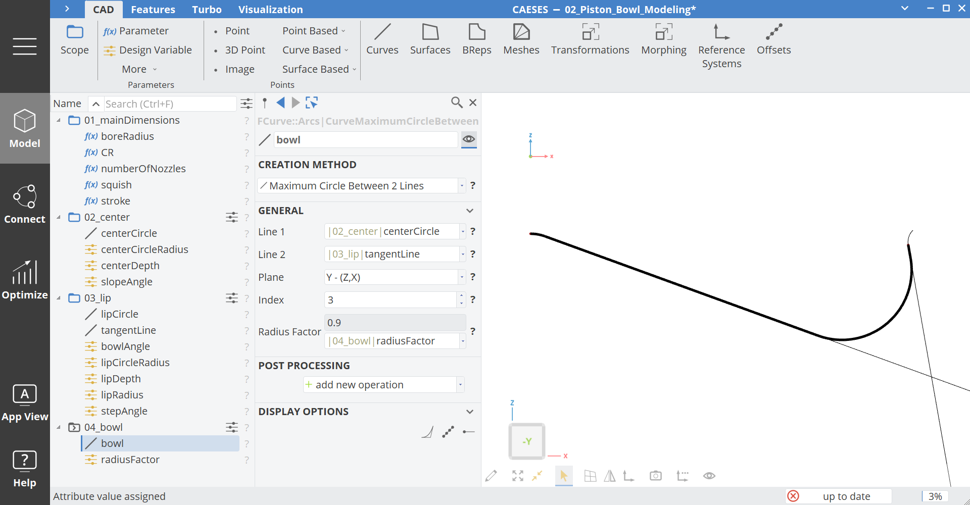
Now it's getting interesting: We need to create the bowl circle between the two tangential lines. We could simply use a circular fillet for this, but this method would not work if the radius is too large. As an alternative we came up with a feature to create a fillet with the maximum fillet radius between two lines. This method makes the geometry really robust during a variation.
- Create a scope via Model > CAD > Scope and set the name to "04_bowl" and make it your working scope.
- Select the two tangent lines centerCircle and tangentLine in this order.
- Create the fillet via Model > CAD > Curves > Arcs > Maximum Circle between 2 Lines. Rename the feature to bowl.
- Set the plane: Y - (Z,X)
- Change the Index to
3. - Set the Radius Factor to
0.9. - Create a Design Variable for the Radius Factor via right click and rename it to radiusFactor.
The Radius Factor controls the size of the fillet relative to the maximum possible fillet radius.
Step
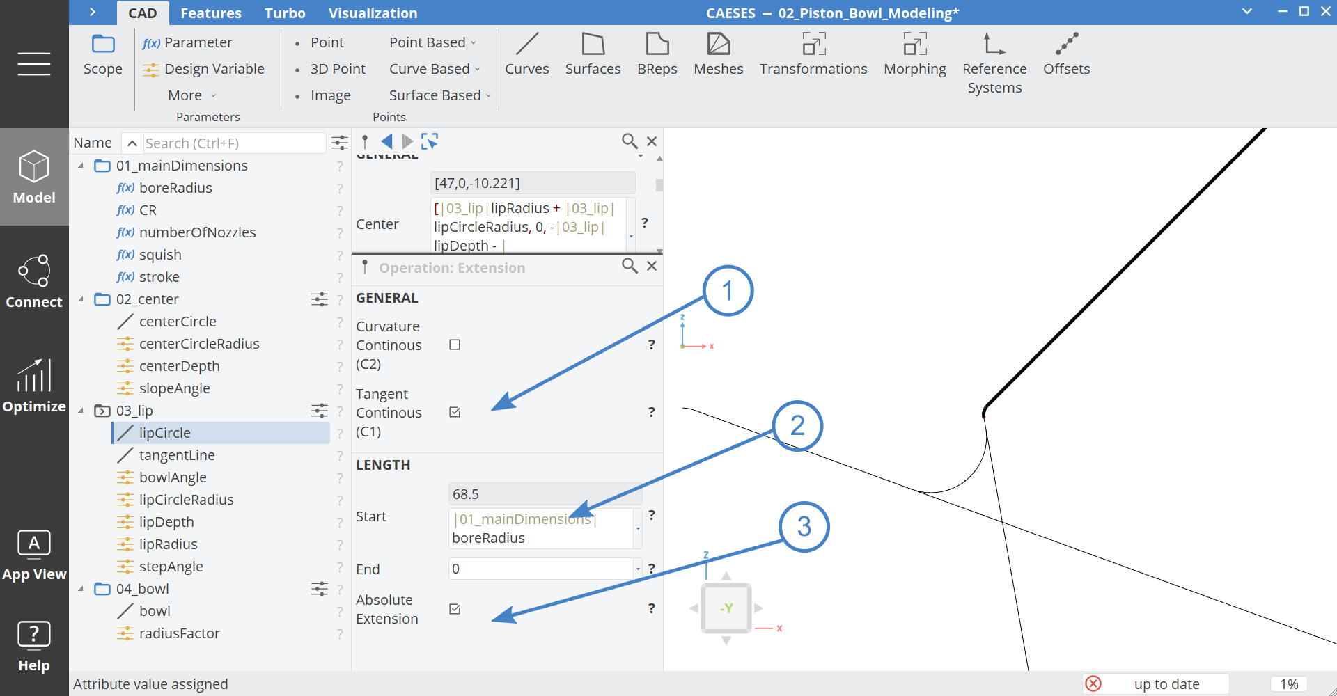
We can create the upper step by simply extending the lipCircle
- Make the scope 03_lip your working scope again.
- Select the curve lipCircle.
- Add a new operation via add new operation > More > Extension.
- Activate Tangent Continuous.
- Set the start value to
boreRadius. - Activate Absolute Extension.
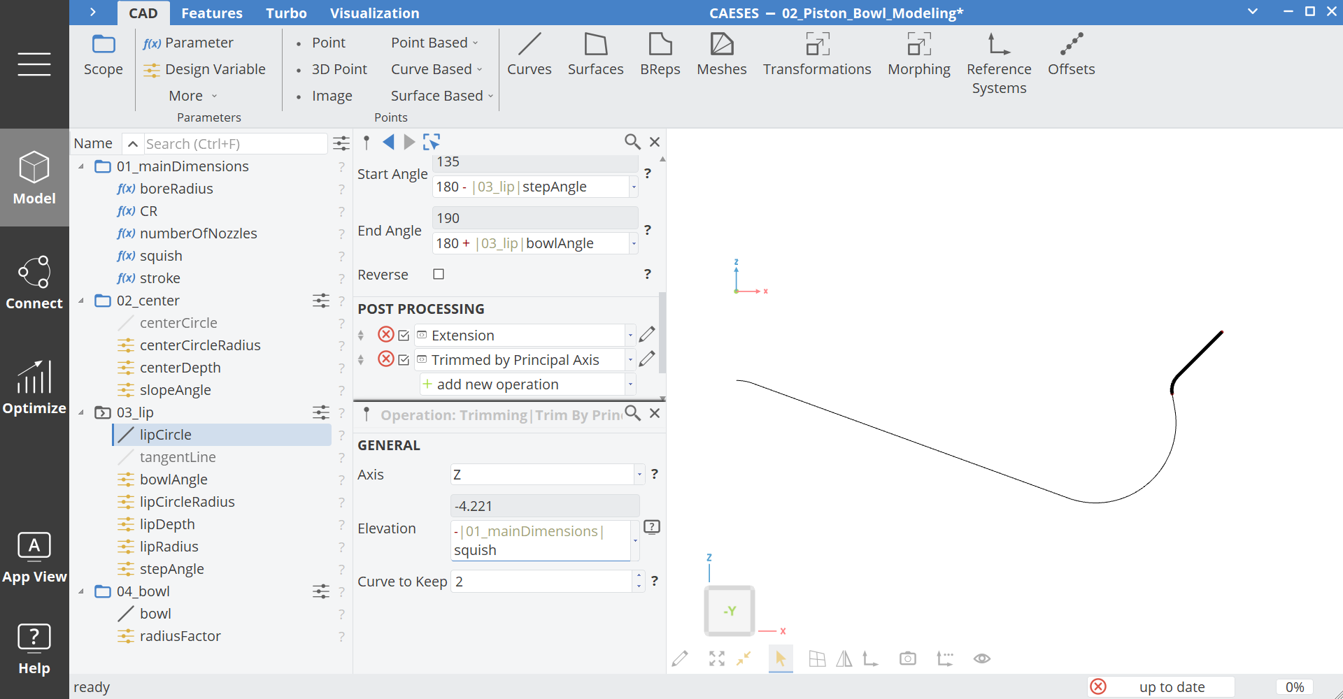
Now we want to trim this curve at the squish z-position.
- Make sure the curve
lipCircleis still selected. - Add a new operation via add new operation > Trimming > Trim by Principal Axis.
- Set arguments:
- Axis:
Z - Elevation:
-squish - Curve to Keep:
2
- Axis:
- Hide the centerCircle and the tangentLine.
Top
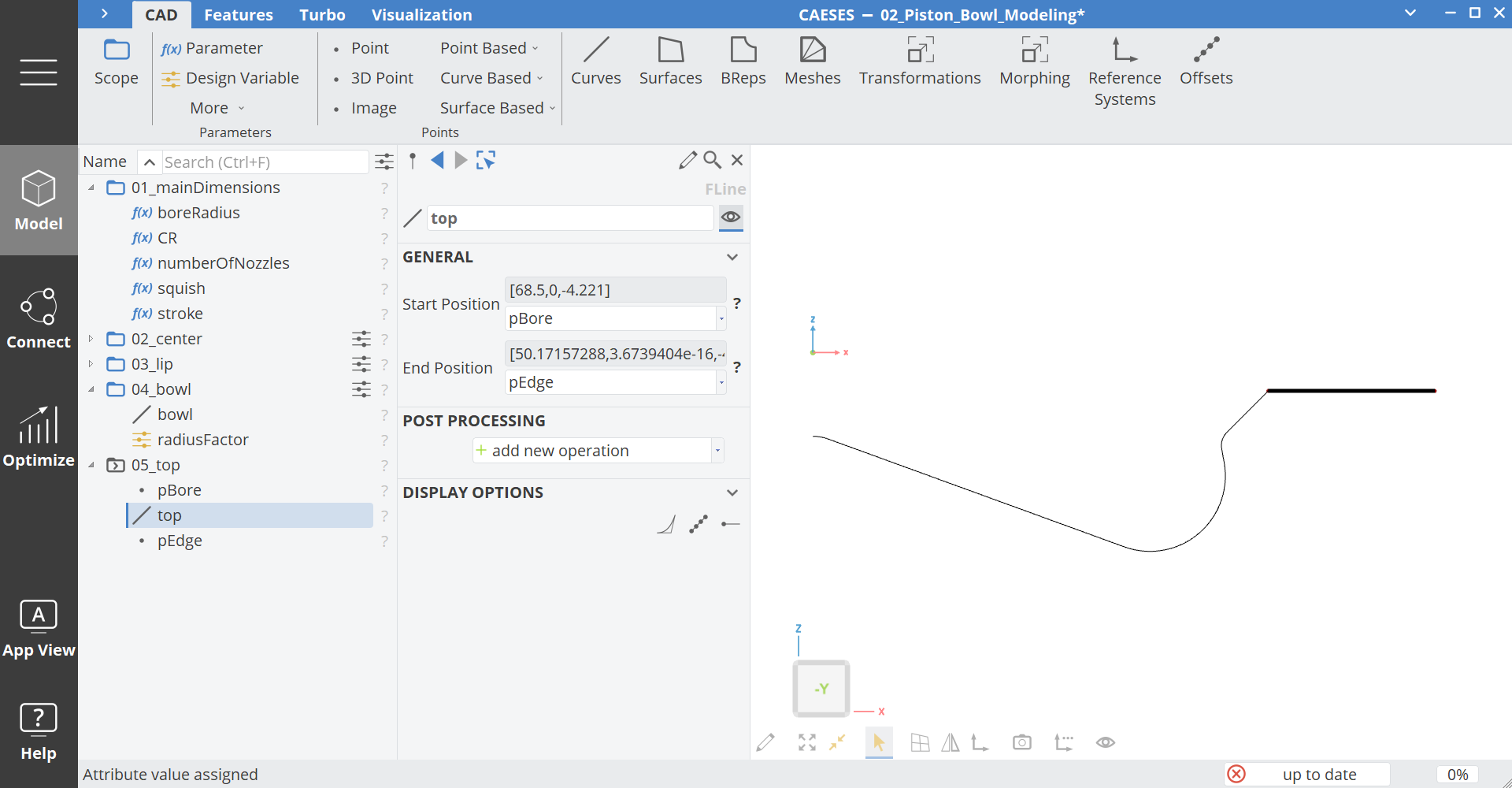
- Create a scope via Model > CAD > Scope and set the name to "05_top" and make it your working scope.
- Create a new point via Model > CAD > Points > Curve Based > Position on Curve and set the name to "pEdge"
- Drag the curve
lipCirclefrom the scope 03_lip into the Curve field, set Tp to0. - Create a new Point via Model > CAD > Points > 3D Point and set the name to "pBore".
- Set the coordinates to:
- X Coordinate:
boreRadius - Z Coordinate:
-squish
- X Coordinate:
- Select pEdge and pBore.
- Create a line via Model > CAD > Curves > Line and set the name to top.
Combine
Now we just have to combine our single curves to one curve.
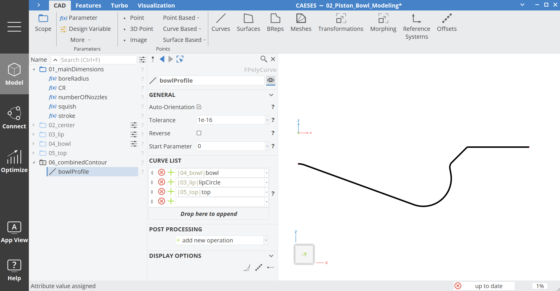
- Create a scope via Model > CAD > Scope and set the name to "06_combinedContour" and make it your working scope.
- Select bowl, lipCircle and top in this order
- Create a poly curve via Model > CAD > Curves > Curve Based > Poly and set the name to "bowlProfile"
- Activate Auto-Orientation
- Make the other scopes invisible.
Piston Bowl Volume Adjustment
An important constraint during a variation of the bowl contour is a constant volume or compression ratio. To achieve this we need a free design variable which is automatically adjusted by a design engine to achieve a certain target volume or compression ratio. This free design variable should have a large influence on the piston bowl volume. Typical design variables for this topology are the bowl radius or the edge radius. In our case we choose the parameter slopeAngle as free design variable.
- Select the Design Variable Slope Angle and set the lower and upper bounds
[10,40].
Compression Ratio Calculation
The volume is calculated using the feature definition "pistonBowl_volumeCalculation", which can be downloaded here:
Load Feature- Drag and drop the downloaded feature definition into the CAESES GUI
- Create a scope via Model > CAD > Scope and set the name to "07_CR_Calculation" and make it your working scope.
- Switch the tab to Model > Features.
- Right click on the feature definition pistonBowl_CRCalculation and select Create Feature
- Switch back to the tab Model > CAD.
- Rename the new feature instance to "calcCR" and set these arguments:
- Curve:
bowlProfile - Stroke:
stroke - CR Target:
CR - Profile includes squish translation:
activate(check the box), since we included the squish parameter in all Z-coordinates - Volume Head:
0, since we have a flat fire deck
- Curve:
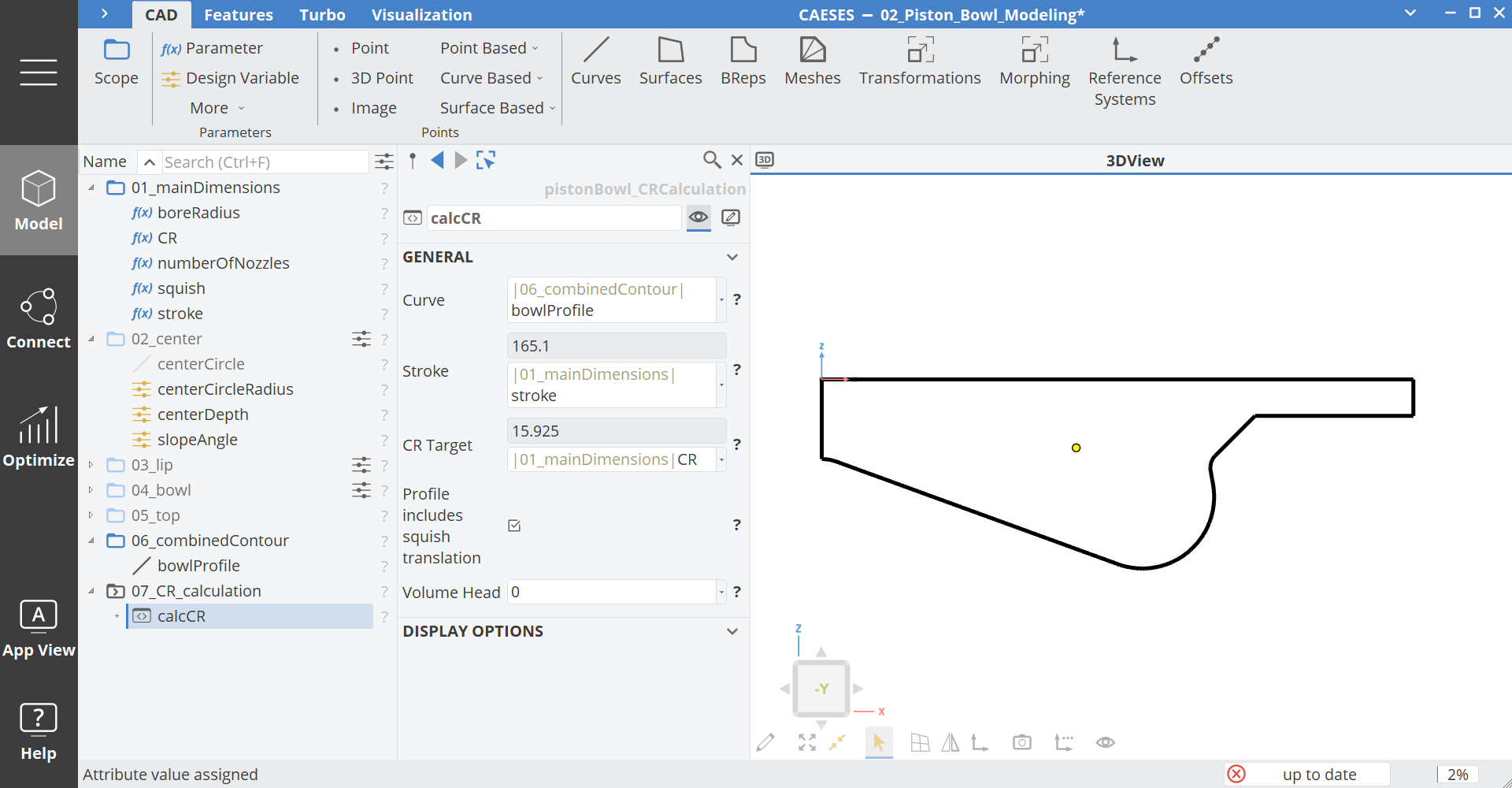
The feature will calculate the volume, CR and the difference to the target.
- Create a parameter via Model > CAD > Parameters > Parameter and set the name to "objective_CR".
- Create a parameter via Model > CAD > Parameters > Parameter and set the name to "CR_current".
- Select objective_CR and set the expression to
calcCR:CRDiff_squaredfrom the feature calcCR. This parameter is the objective for the volume adjustment. It should be zero if there is no difference between target and current volume.
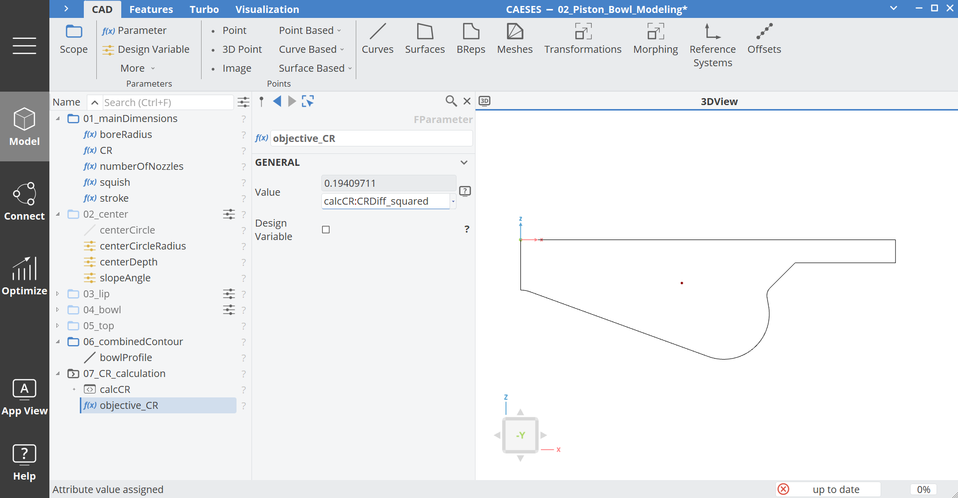
Click on the + icon next to a feature instance in the object tree to expand all accessible attributes.
Compression Ratio Adjustment
Now we can create a design engine for the volume adjustment.
- Create a new Design Engine Optimize > Optimization > Single Objective Optimization > Brent and set the name to "CRadjustment"
This design engine is a simple gradient based single objective algorithm, which can vary one design variable.
- Set the slopeAngle as the design variable.
You can see that the lower and upper bounds are automatically set, since we already set the bounds at the design variable.
Note that the bounds set in the design engine are not updated automatically, if you change the bounds directly at the design variable. To update the design engine with the new bounds set at the design variable click on the left button below the design engine table.
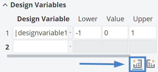
- Set the parameter
objective_CRas an evaluation and set the objective to min for a minimization
Now we have to decide how many iterations we need to minimize the objective parameter.
- Set the number of iterations to
20
Since we don't want to create a design table for each volume adjustment, we need to deactivate the design creation:
- Click on the general tab of the design engine to show more options. Here deactivate the toggle Variant Creation.
- Here also activate the option Keep up to Date, which will trigger this engine automatically if the geometry is updated.
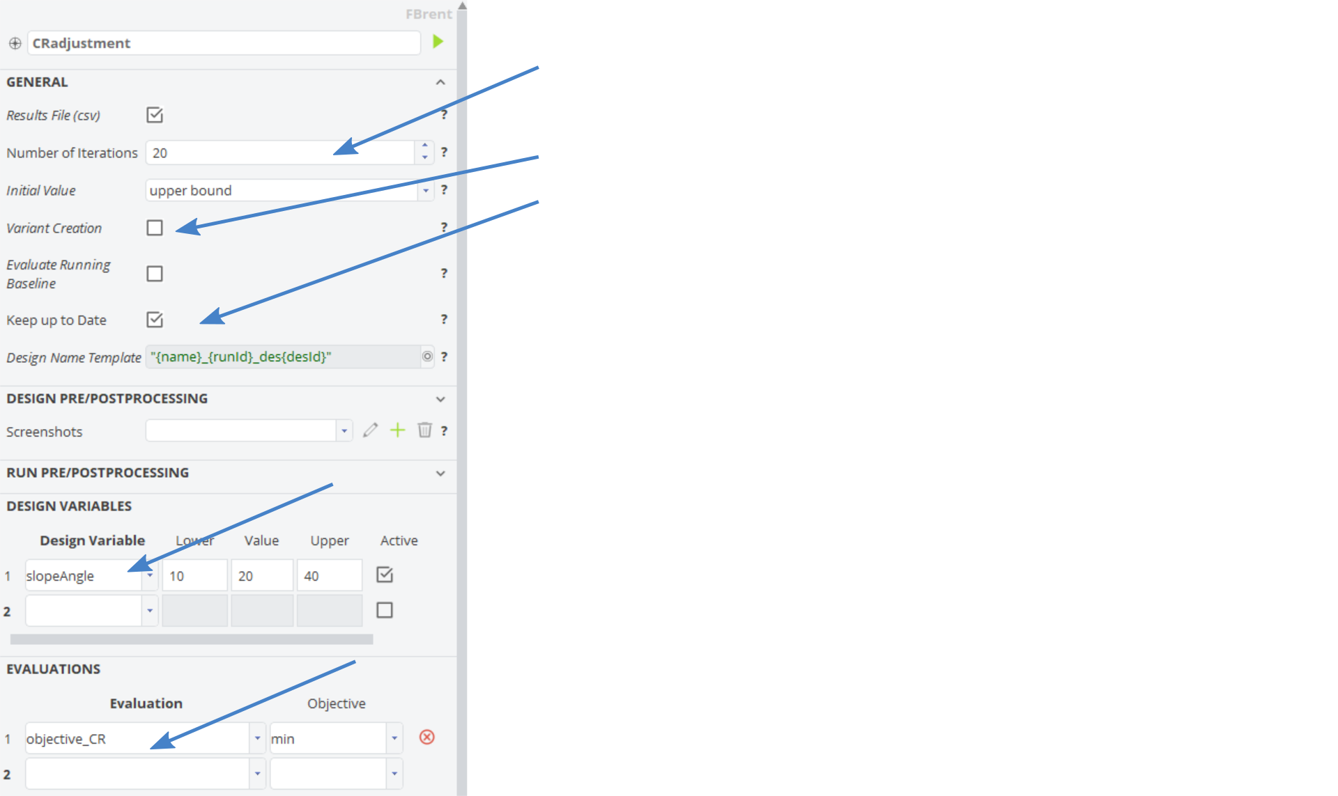
Now we can test if the adjustment works properly.
- Go back to Model > CAD
- Change for example the Design Variable centerDepth to
4. - Now select the parameter objective_CR and check if the value is close to 0.
If it is not close to 0, you may have to open up the bounds of the design variable inside the Brent design engine or increase the number of iterations.
Piston Bowl Exports
There are several ways to export the geometry to different software:
- Export the bowl spline as a text file
- Export a solid sector of the geometry
- Export a solid as full 360° geometry
Export as Bowl Spline
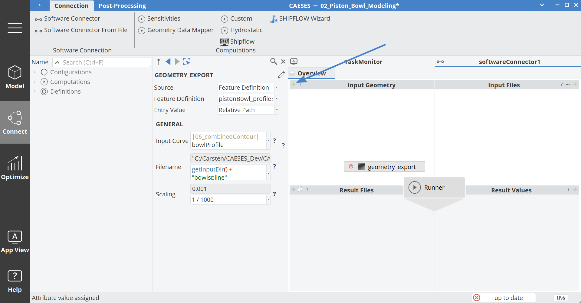
With this method we need the feature "pistonBowl_profileExport", which writes the x and z coordinates into a file. You can download the feature here:
Load FeatureSet the arguments as:
- InputCurve:
bowlProfile - Filename:
getInputDir() + "/bowlspline.dat" - Scaling:
1/1000
When we want to use this feature inside the software connector, we can drag the feature definition into the Input Geometry field and set the arguments as above:
Export as Sector Solid
For this method we can use the feature definition "pistonBowl_solidSegment", which you can download here:
Load FeatureSet the arguments as:
- Profile:
bowlProfile - Scaling:
1/1000 - Arc: Set the arc angle depending on the number of nozzle holes
- Squish:
0since we already included the squish in the profile
If Converge is used as a solver, set the boundary ID's according to the CONVERGE setup.
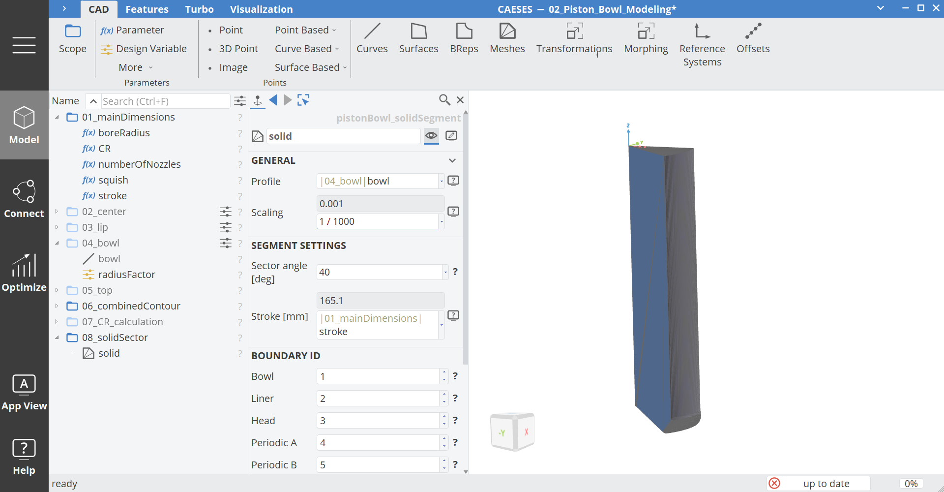
Here you can see how to set up an export to CONVERGE inside the software connector:
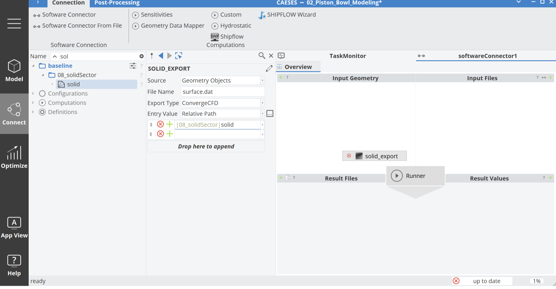
In this case you only have to drag the feature segment to the Input Geometry tab of the software connector and set the filename and export type.
Piston Bowl Variation
Before we start our CFD calculation we always check if the geometry works in the defined design space. This is easily possible by setting up a Sobol design engine, where we set our design variables.
- Select the parameters: bowlAngle, centerDepth, lipCircleRadius, lipDepth, lipRadius, stepAngle
Now set the bounds for the design variables by a click on the edit symbol next to the design variable value. Then set the bounds like shown in this table:
| Design Variable | Default Value | Lower Bound | Upper Bound |
|---|---|---|---|
| bowlAngle | 10 | -20 | 20 |
| centerDepth | 5 | 3 | 8 |
| lipCircleRadius | 2 | 1 | 3 |
| lipDepth | 6 | 3 | 10 |
| lipRadius | 45 | 43 | 50 |
| stepAngle | 45 | 20 | 60 |
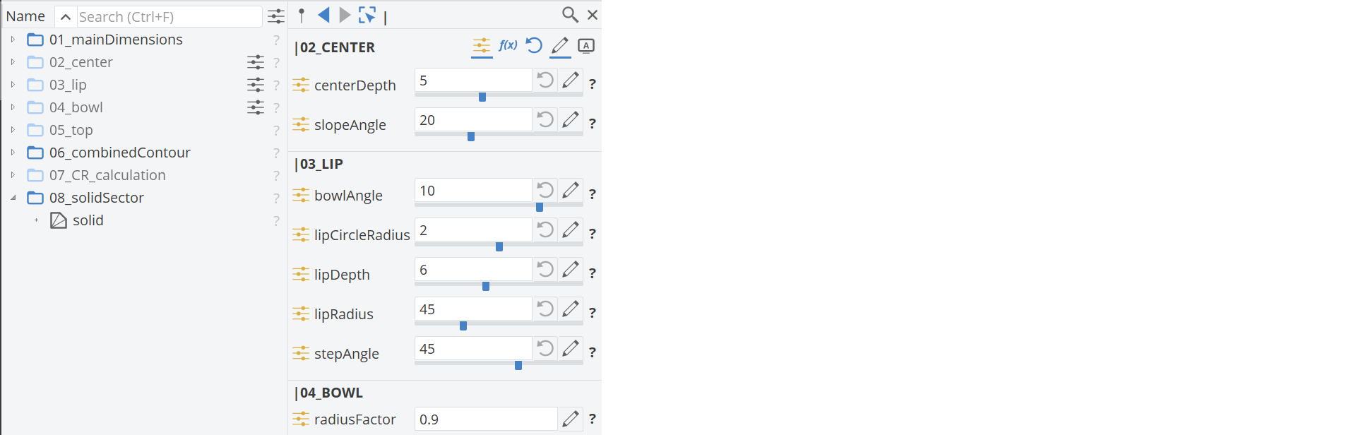
-
Next, create a Sobol design engine via Optimize > Optimization > Design Space Exploration > Sobol
-
Set the number of variants to
20. -
Create a new Screenshots Collection.
-
Use all design variables which we set up, but not centerSlopeAngle, since this will be adjusted by the design engine CR_adjustment.
-
Set the parameter CR_current as an evaluation to see if the target CR was achieved
Here is an example of the setup and the design variable bounds for this case:
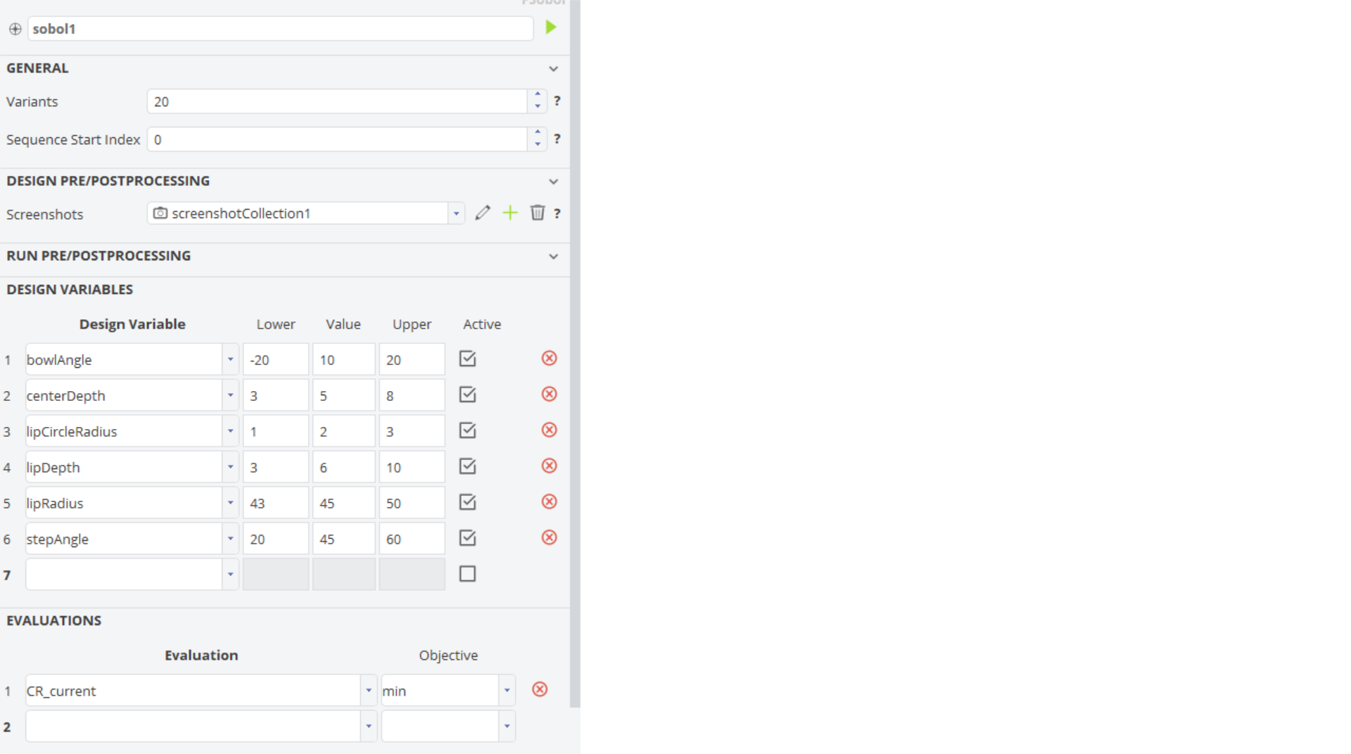
After the Sobol run has finished we can check the parameter CR_current to see if the target compression ratio was achieved. We can also have a look into the design viewer to check feasibility of the designs.
Software Connection
In this step we will connect CAESES with CONVERGE:
- Create a Software Connector: Connections > Software Connector
- Drag and drop the segment which you want to export into the upper left window of the Software Connector
- Set the filename to surface.dat
- Set the Export type to CONVERGE
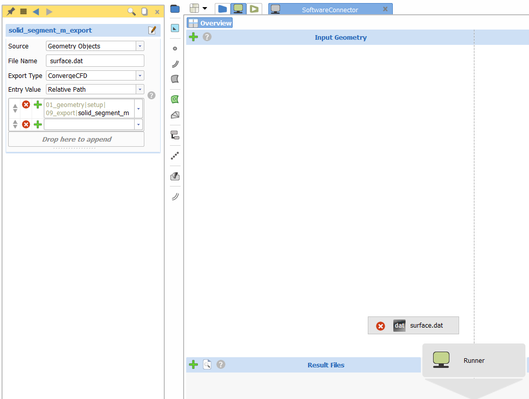
Next add the CONVERGE Input files to the upper right window of the Software Connector:
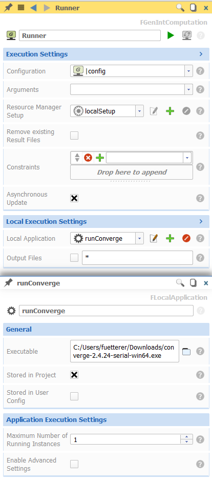
- Set the maximum number of Running Instances: This value will define how many designs are calculated parallel next to each other during a variation. 0 means that it uses the default value from the CAESES preferences.
Add template results files to the lower right part of the Software Connector:
- Click on the Plus button next to Results Values
- Add for instance the emissions.out file
- After added to the Software Connector, double click on the file, to access it
- Create a new value, by clicking on the Plus button
- Rename the value to "NOx"
- Put the line number to
-1. This means it will use the last entry of the column - Set the Column to
2 - Click on the blue parameter button next to NOx to create a new parameter for the NOx value
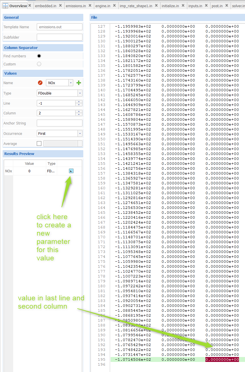
Test the connection by selecting the Runner and clicking on the run button. You can see the status in the Task Monitor after the computation has finished: you should have a value called eval_NOx in the parameter for NOx.
If you want to trigger the software connection inside a variation e.g. a Sobol, then you just have to add the parameter eval_NOx to the evaluation of the design engine.
CAESES Project File
If you want to take a look at the finalized parametric model you can find the resulting CAESES project file piston-bowl-modeling.cdb here: