Basic Connection - Jumper
Introduction
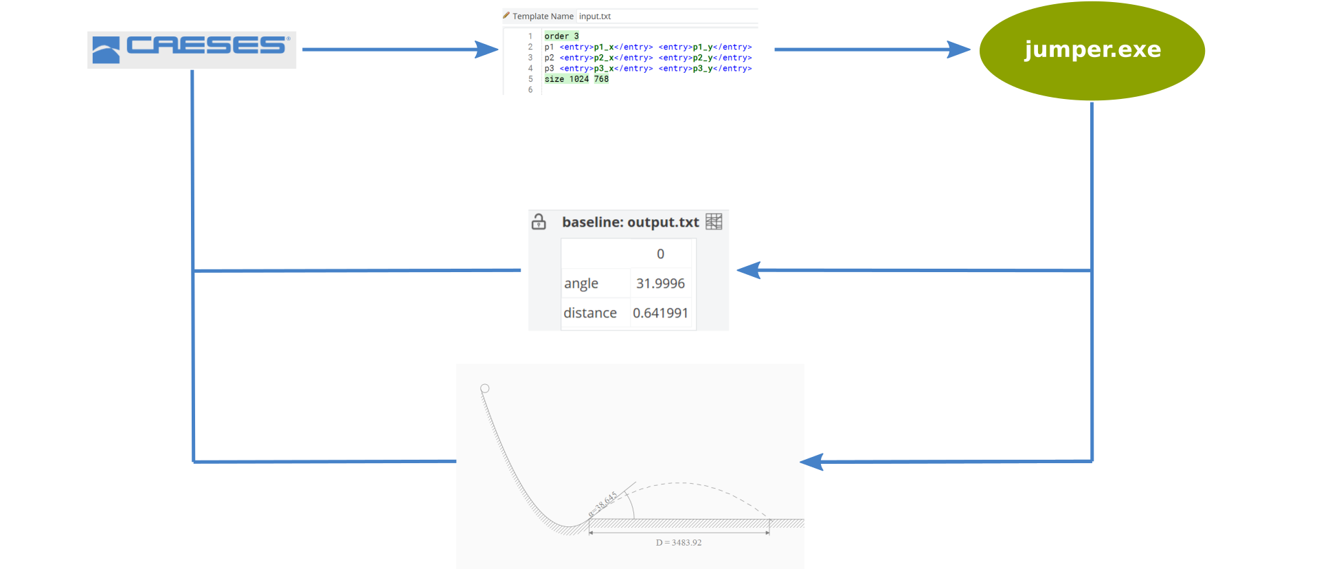
This tutorial shows how to setup a Software Connector to conduct a geometry optimization based on simulation results. We setup a demonstration project in which a B-Spline curve is used to describe the shape of a ramp. The optimization objective is the maximum free flight distance of a ball which is dropped at the highest point of the ramp. The trajectory computation for the ball is conducted using the external program "jumper.exe". The tutorial demonstrates:
-
Basic concepts for 3rd party simulation software integration with CAESES,
-
Data Exchange between CAESES and external software components,
-
Setup of univariate design optimizations.
Software Connector
Software connectors are used to drive external software packages from within CAESES. Using software connectors, third party simulation tools are integrated to analyze particular designs of a parametric model, or to conduct an optimization for a specified set of design variables. The software connector defines how data is exchanged between CAESES and the external software and how the external software is invoked.
The management of Software Connectors is exposed to the user in the CAESES Connect workspace. For this tutorial, we create a new Software Connector from scratch in order to link an external computation tool with the aim of finding the (optimum) shape of the ramp that results in the maximum thrown distance.
To create a new Software Connector, go to workspace Connect, choose the Connection Tab and click on Software Connector (to be found in the Software Connection Group).
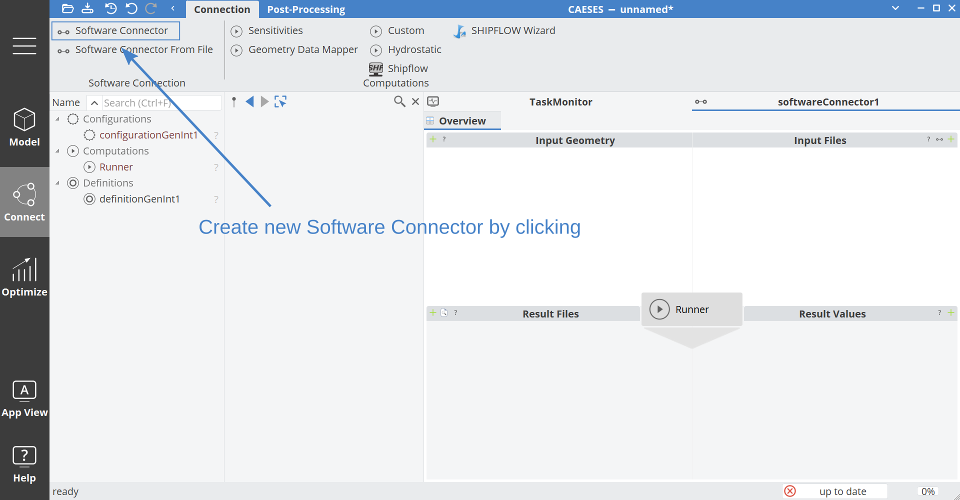
The creation of a new Software Connector automatically triggers the creation of a "Computations" element with the "Connector1".
A Configuration object represents the data exchange and model dependent computation setup for an external computation software or toolchain. For the example of a CFD simulation, the Configuration may provide settings for data export, automated meshing, solver settings, boundary conditions, and importing of results data. The Configuration does expose the required settings to the external computation by means of Input Files (to the external computation). In addition, Output Files (of the external computation) may be specified in the Configuration to gather simulation results for further processing in CAESES.
A Computation object holds information on the external application that is invoked to trigger an external computation run. For a host local application the settings typically specify the executable path, batch mode arguments, and constraints.
Another possibility is the execution of the external computation on remote hosts by the utilization of the Slurmbridge module of the CTC Server.
Loading an External Tool Input File
In this tutorial, the input for the external computation tool is a plain text ASCII file. The text file supplies the computation tool with the coordinates of three points. On invocation the computation tool reads the three input points from the file, internally creates a cubic B-Spline curve that defines the shape of the ramp, and then computes the accelerating motion of the ball.
We now create an input file template from an existing file. Click the "+" icon in the top right corner of the Input Files quadrant of the Software Connector "Overview" visualization. Select the file "input.txt" which is located in the "Samples/Integration/Jumper/" subfolder of your CAESES installation directory. The newly added file is represented by an icon in the Input Files quadrant.
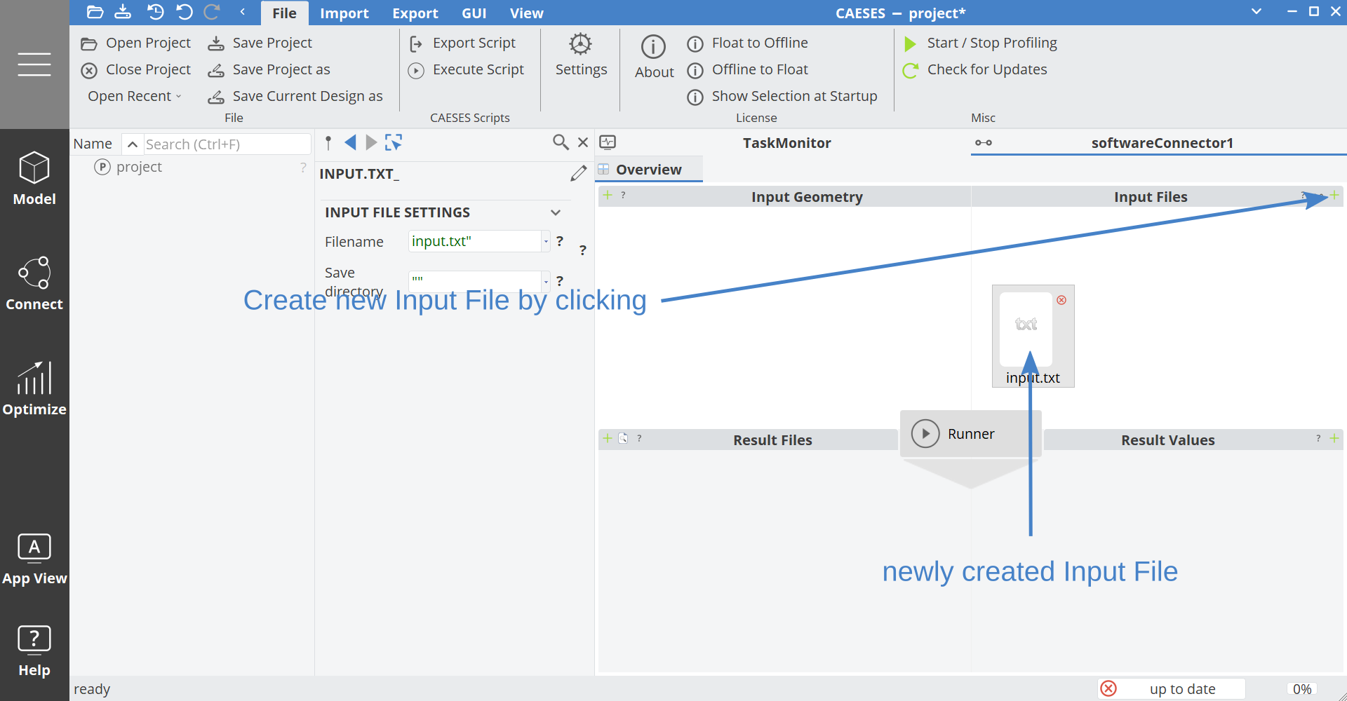
By default, the added Input File is a reference to a physical file on the system. By double clicking on the file icon it is converted to an internal file which can serve as a template for a parameterized Input File. In the process of creating a template from the file, the icon is updated with a preview of the file contents and the template editor is opened.

Preparing the Input File Template
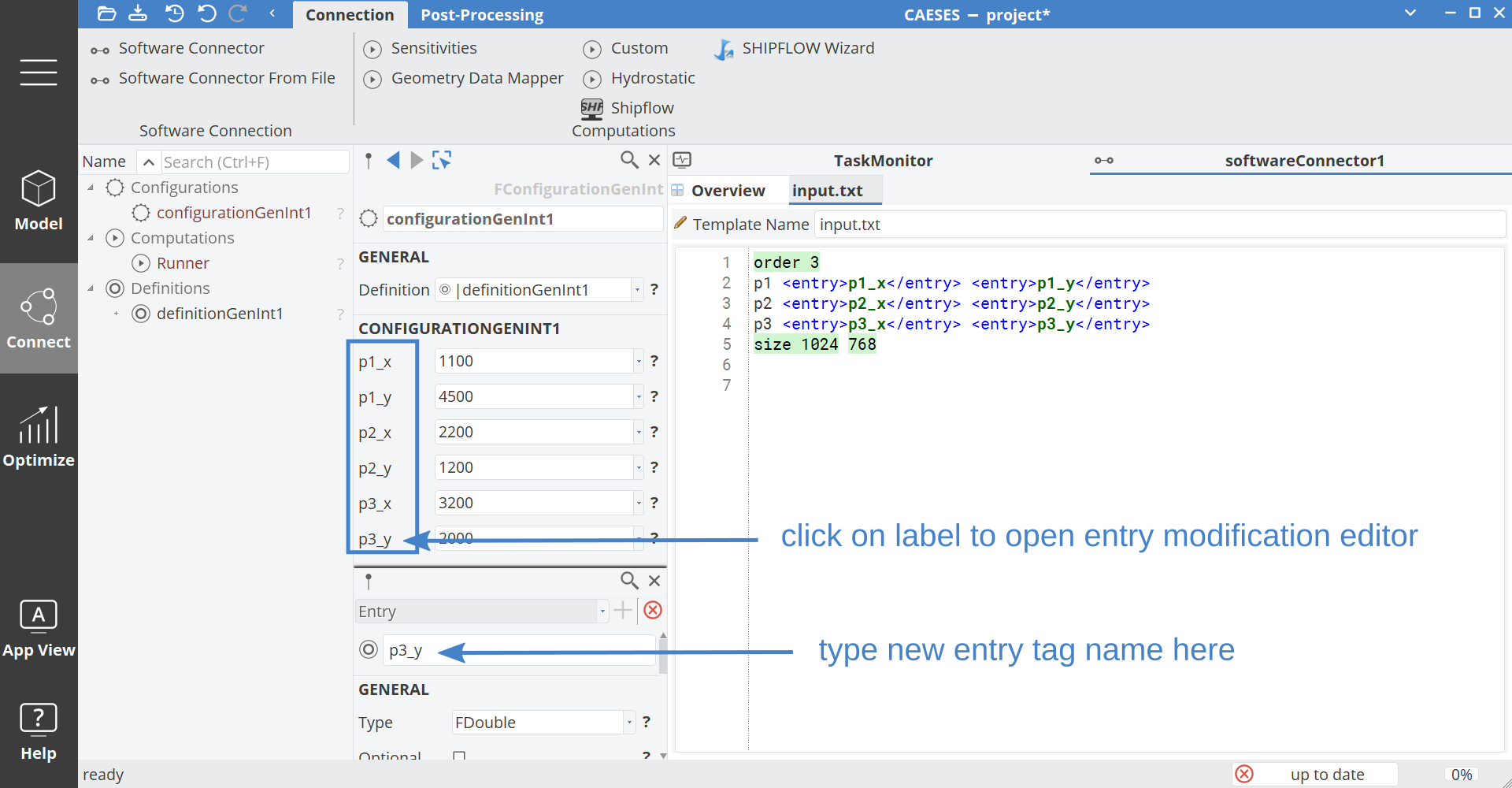
The next step is the replacement of the fixed point coordinate values in the input template by variables. During the optimization run the variables will be set to particular values that are derived from the model geometry. To create the variables, hover and click on the point coordinate numbers as indicated in the screenshot below.
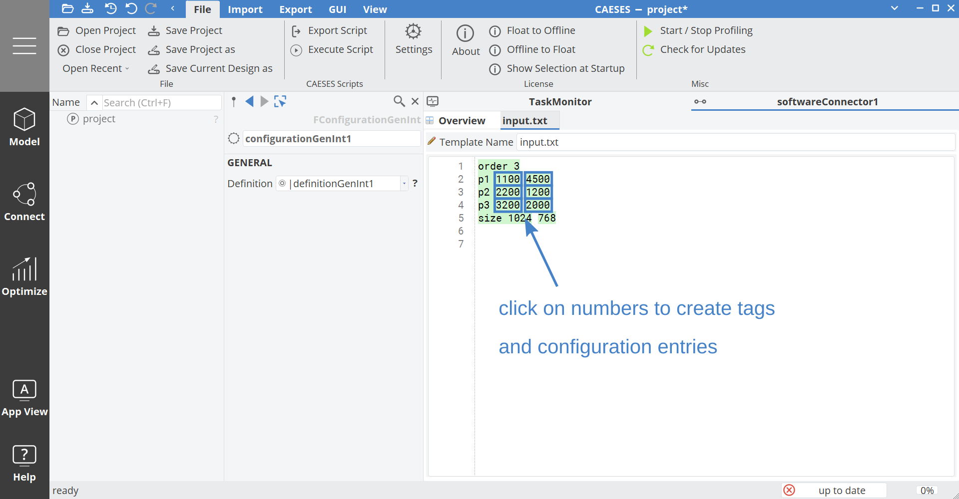
The names of the newly generated template entries can now be modified to be more expressive. This is done by clicking on the entry names in the configuration editor and then updating the new names in the newly opened settings editor. Rename the six input coordinates as "p1_x" to "p3_y" as shown in the following screenshot
Parsing the ASCII Output File
The results of the external computation are made available in CAESES for further processing via Result Files and Result Values. In this tutorial we are interested in a particular value (the resulting distance) which can be parsed as a Result Value. Now, create a new Result Values file based on an existing file by clicking the "+" button of the quadrant and selecting the file "output.txt" that is located in the "Samples/Integration/Jumper/" subfolder of your CAESES installation directory.
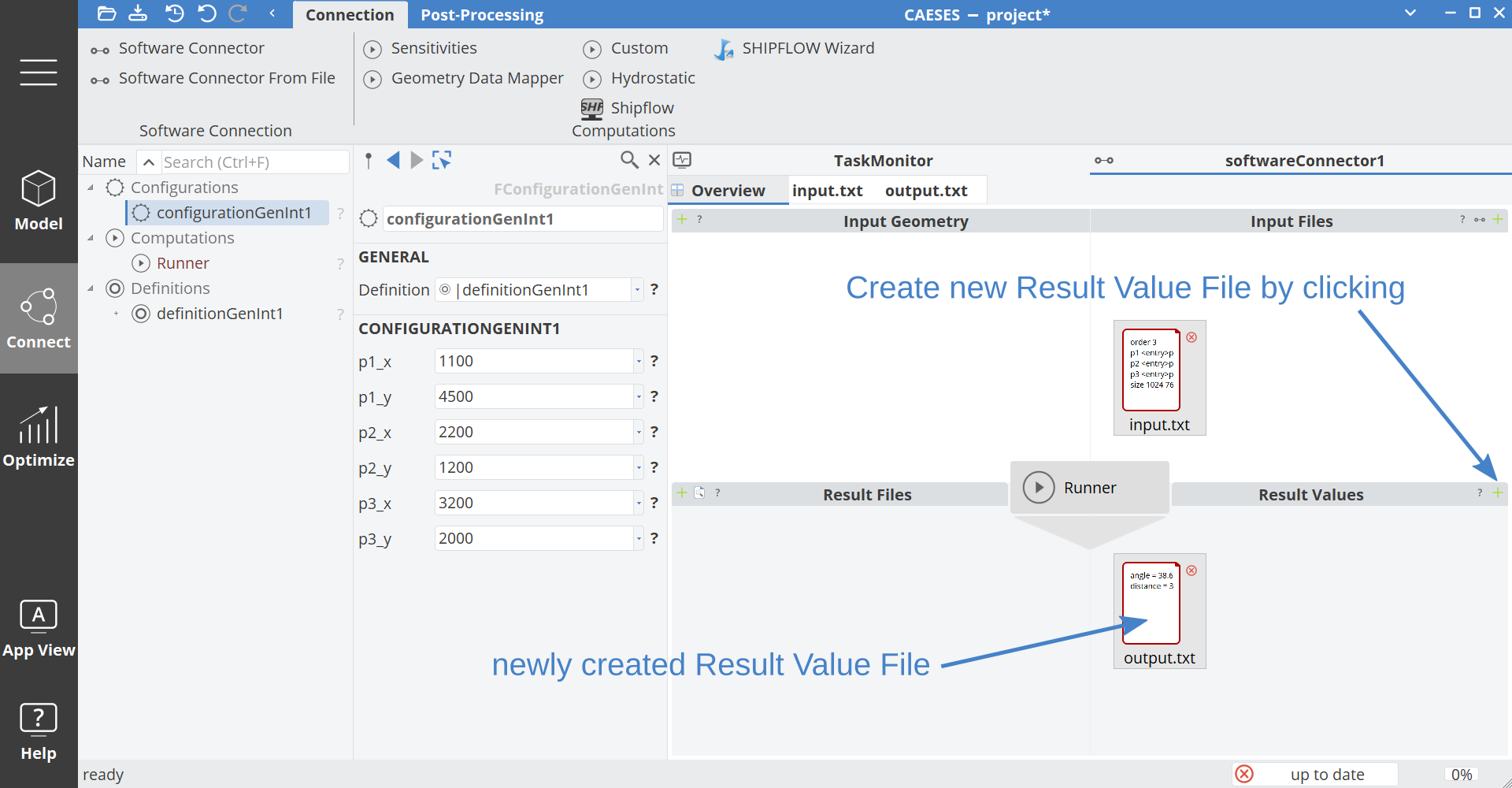
We now set-up the data extraction mechanism for the Result Value file. To do so, double click on the output.txt Result Values file icon.
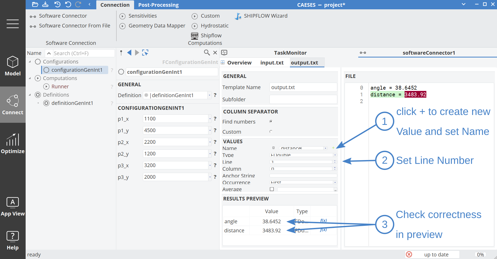
The newly opened editor aids in setting up the data extraction process. Create a new data value by clicking "+". Name the first value "angle" and specify Line 0 for data extraction. Add another result value by clicking "+" again and name it "distance". Set data extraction line number for "distance" to 1. Now check the result values as parsed by CAESES for correctness by comparing values in the Results Preview
and the file contents.
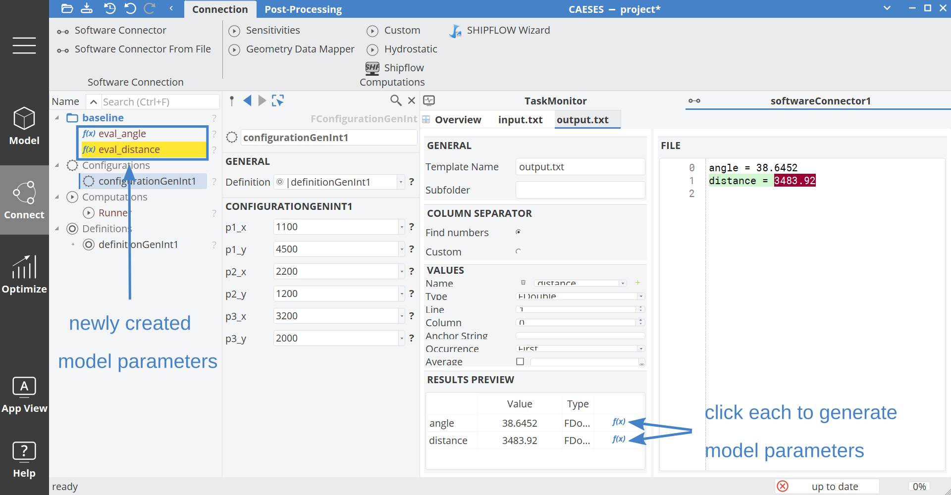
The result values are now made available to the model and optimization process by the creation of one parameter for each value. The parameters are created by clicking on the blue f(x) icon in the Results Preview data table.
PNG Result File
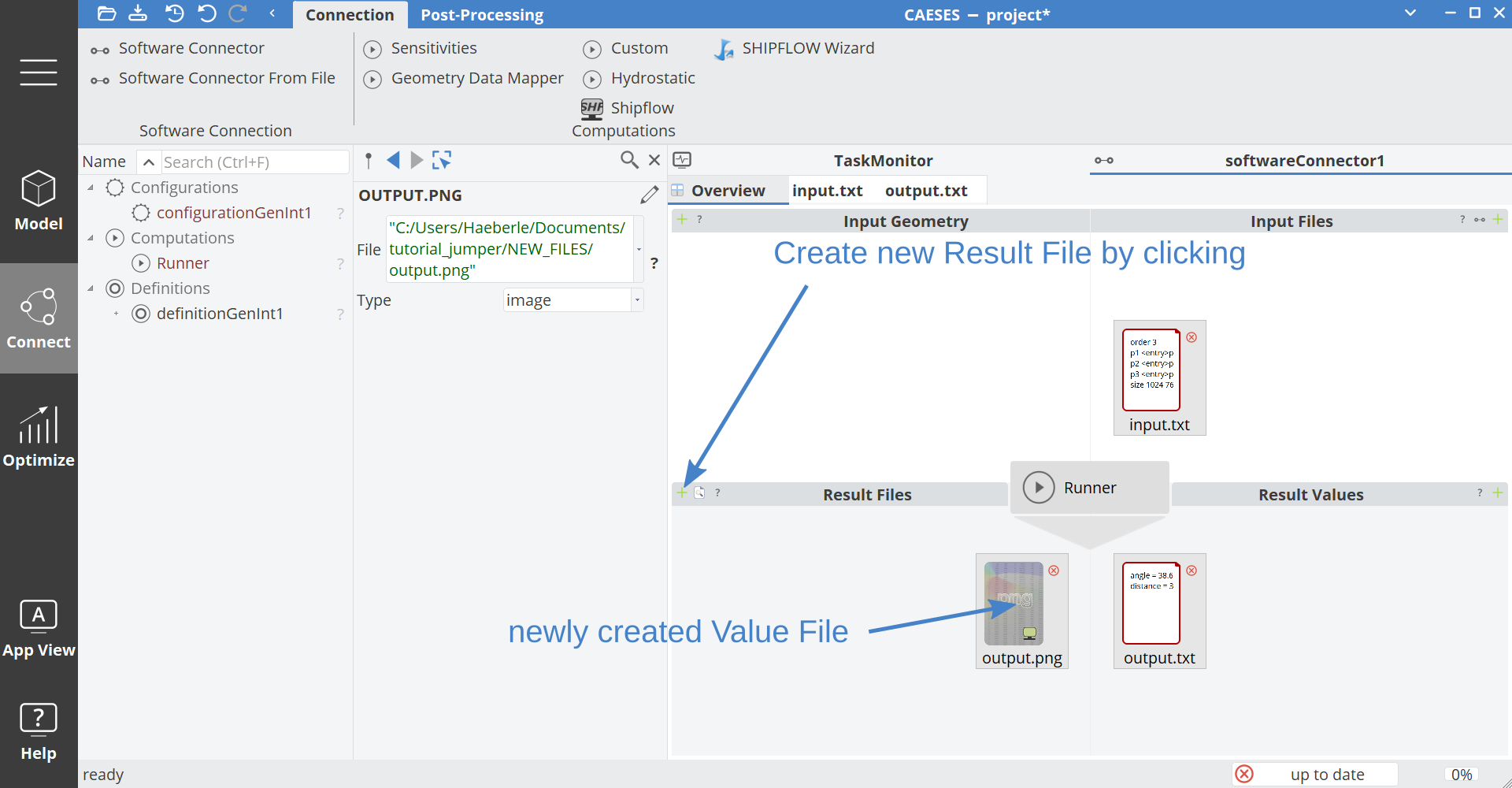
In addition to the text results file, the external computation tool provides a visualization of the ball trajectory by means of a PNG image. We now import the PNG image for later visualization in CAESES.
Add the PNG file as a Results File by clicking on the corresponding “+” button. The output.png is located in the Samples/Integration/Jumper/ subfolder of your CAESES installation directory.
Geometry Modelling
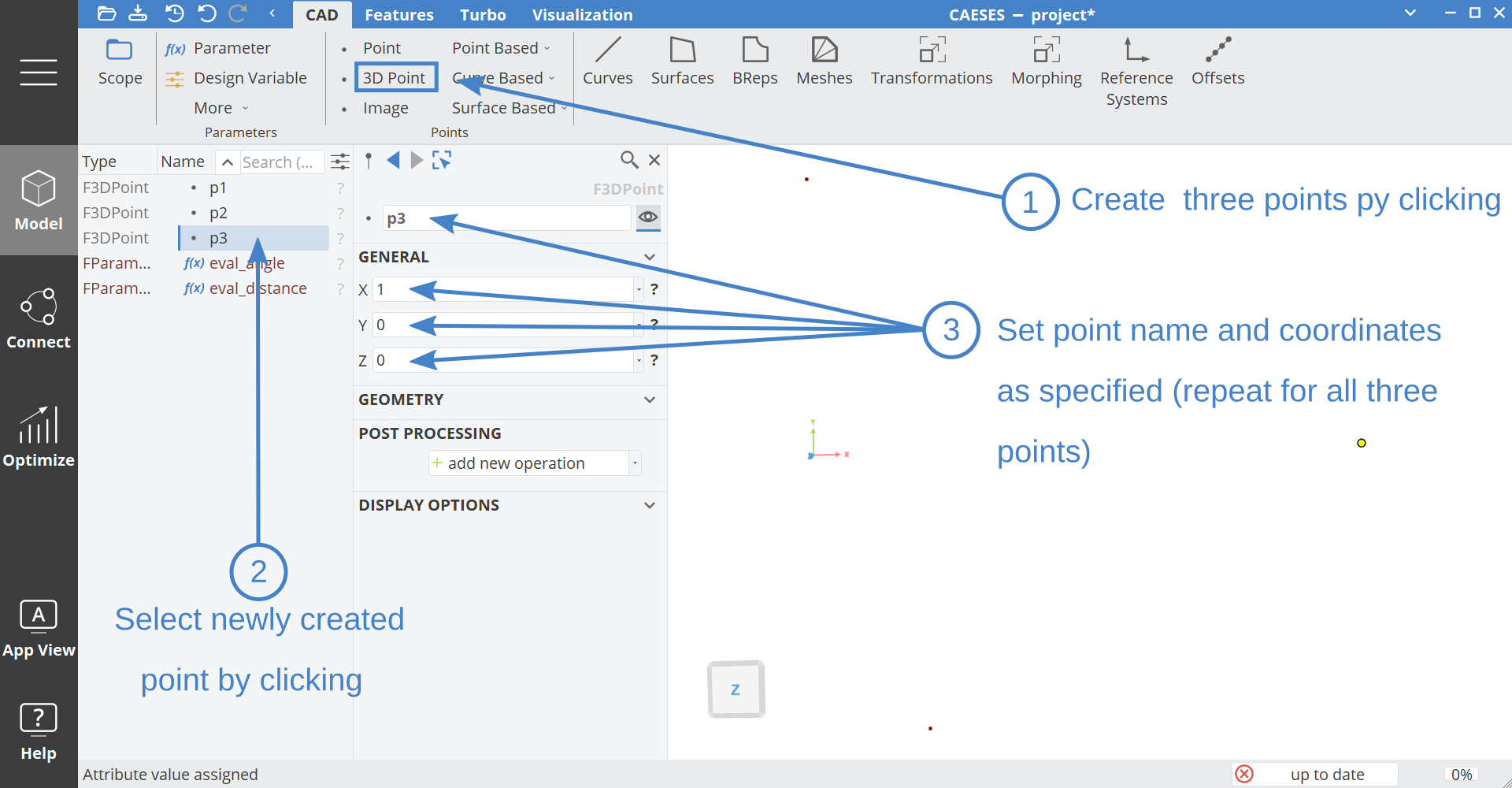
We now prepare a geometric model for the ramp geometry using a B-Spline curve. In a first step, we create three points upon which the B-Spline curve will be based. Select the Model workspace in CAESES and create three points by clicking 3D Point in the CAD tab. Rename the points as shown in the following screenshot and set the initial point coordinates as follows:
- p1 =
[0, 0.5, 0] - p2 =
[0.2, -0.5, 0] - p3 =
[1.0 ,0 ,0]
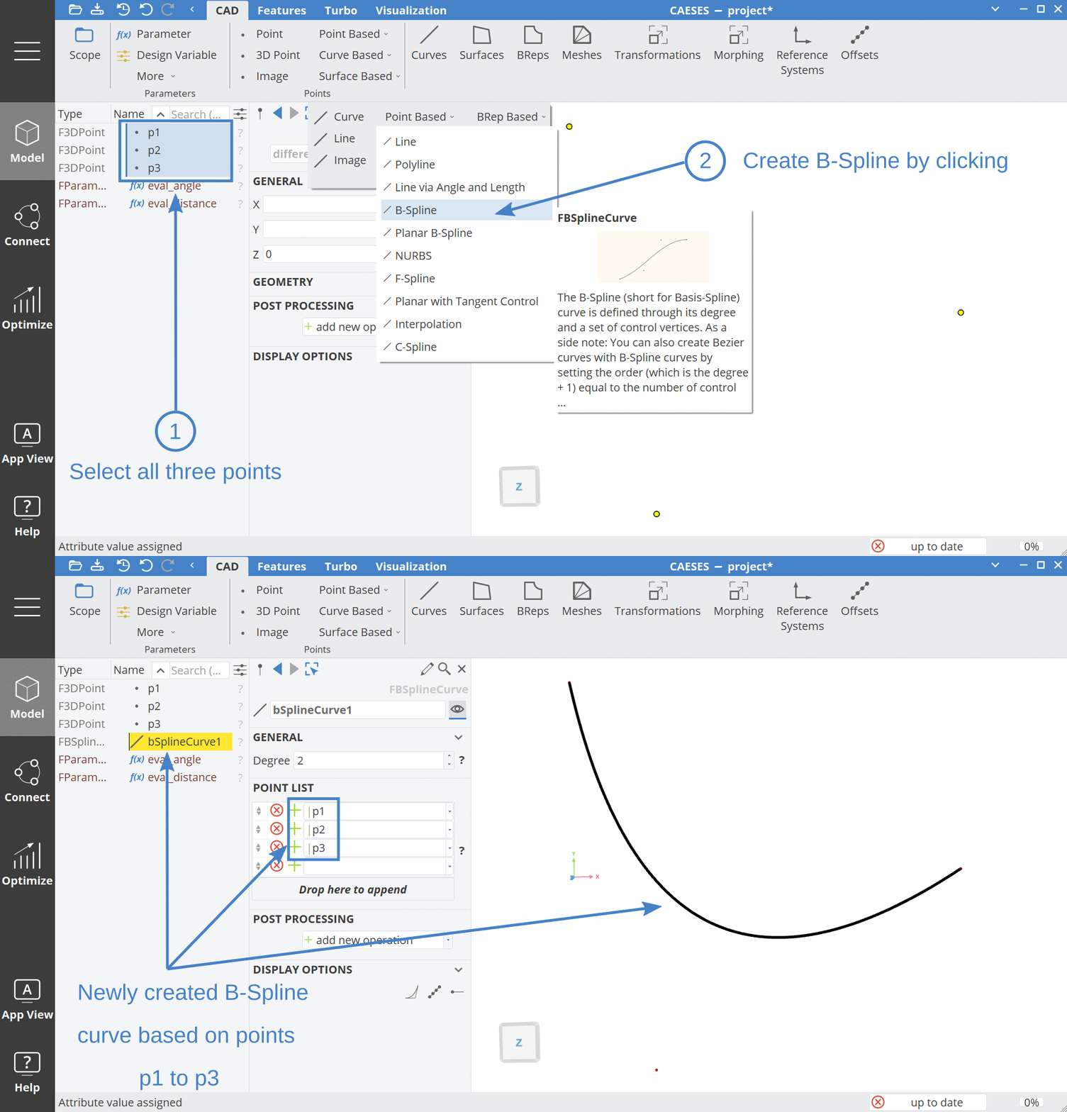
Now create a B-Spline curve that is based on the three points p1 to p3. To do so, select p1 to p3 in the object tree and select B-Spline in the Point Based menu under curves as shown below.
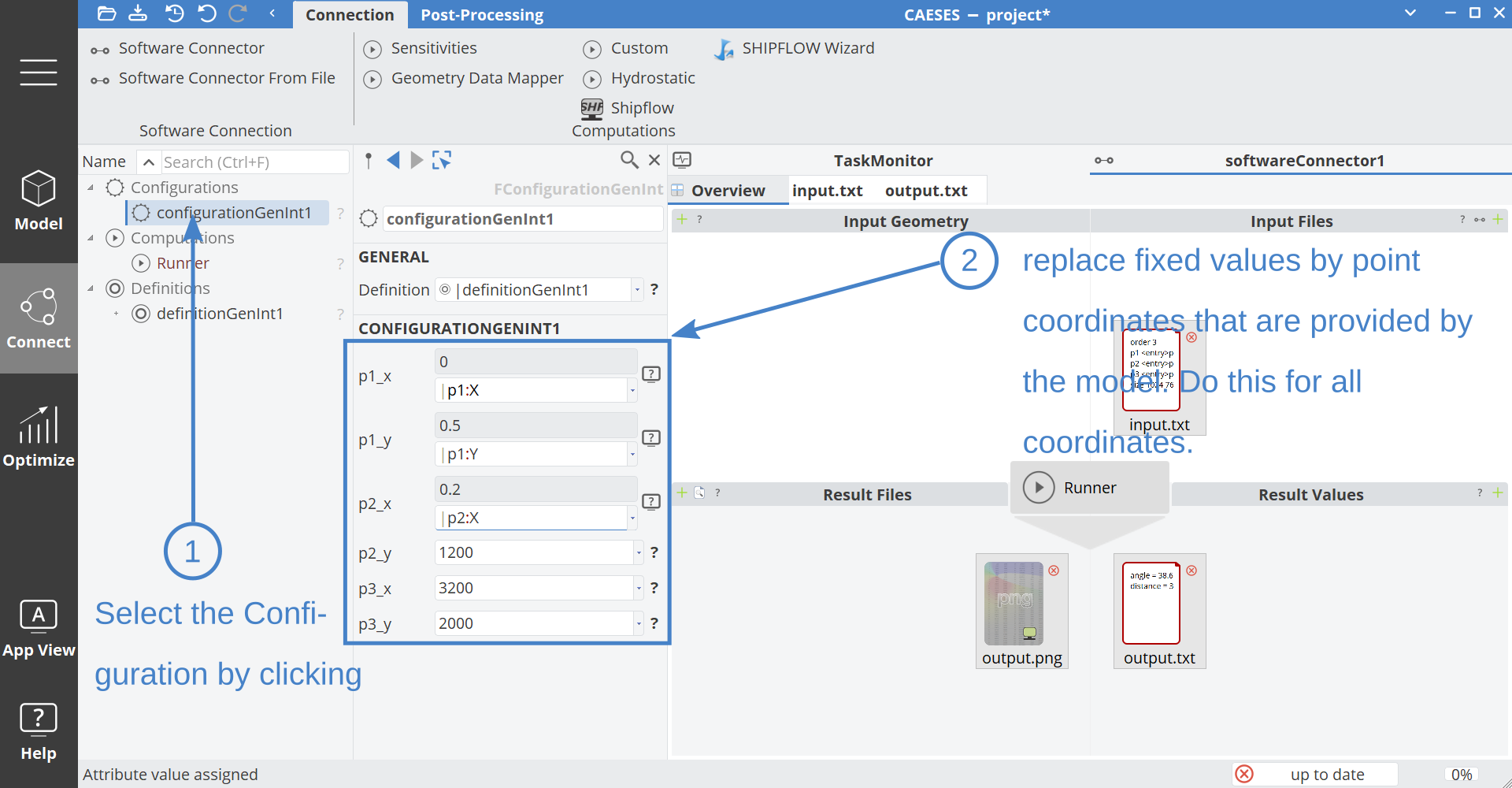
In the next step, we connect the model geometry information to the Software Connector Configuration Input File template. Enter the Connect workspace and select the Software Connector Configuration by clicking. Now link the model point coordinates p1_x to p3_y to the Input File template as illustrated below. After connecting, CAESES will supply the point coordinates of the model's points for the external computation's input file whenever an external computation is triggered.
Computation Setup and Test Run
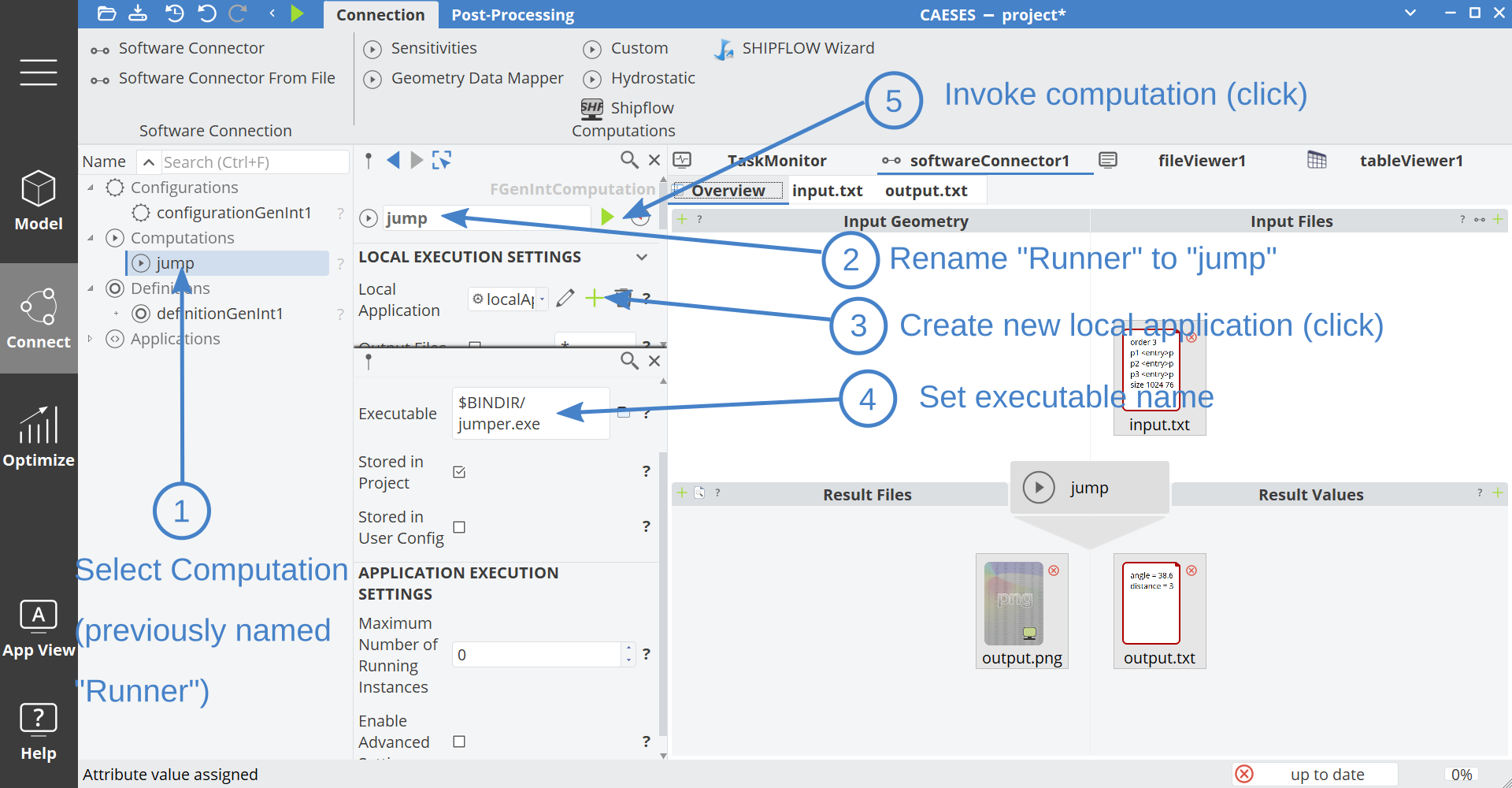
We now setup the Software Connector Computation. For this tutorial we set up a local computation. In the Connect workspace, select the auto-generated Computation Connector1 and rename it to "jump". Then create a new local application by clicking the "+" button next to Application in the Execution Settings. Update the name of the executable to $BINDIR/jumper.exe (set to $BINDIR/jump on Linux).
$BINDIR is an environment variable that points to the binary applications folder of your CAESES installation. Finally start the external computation by clicking the green run button.
Results
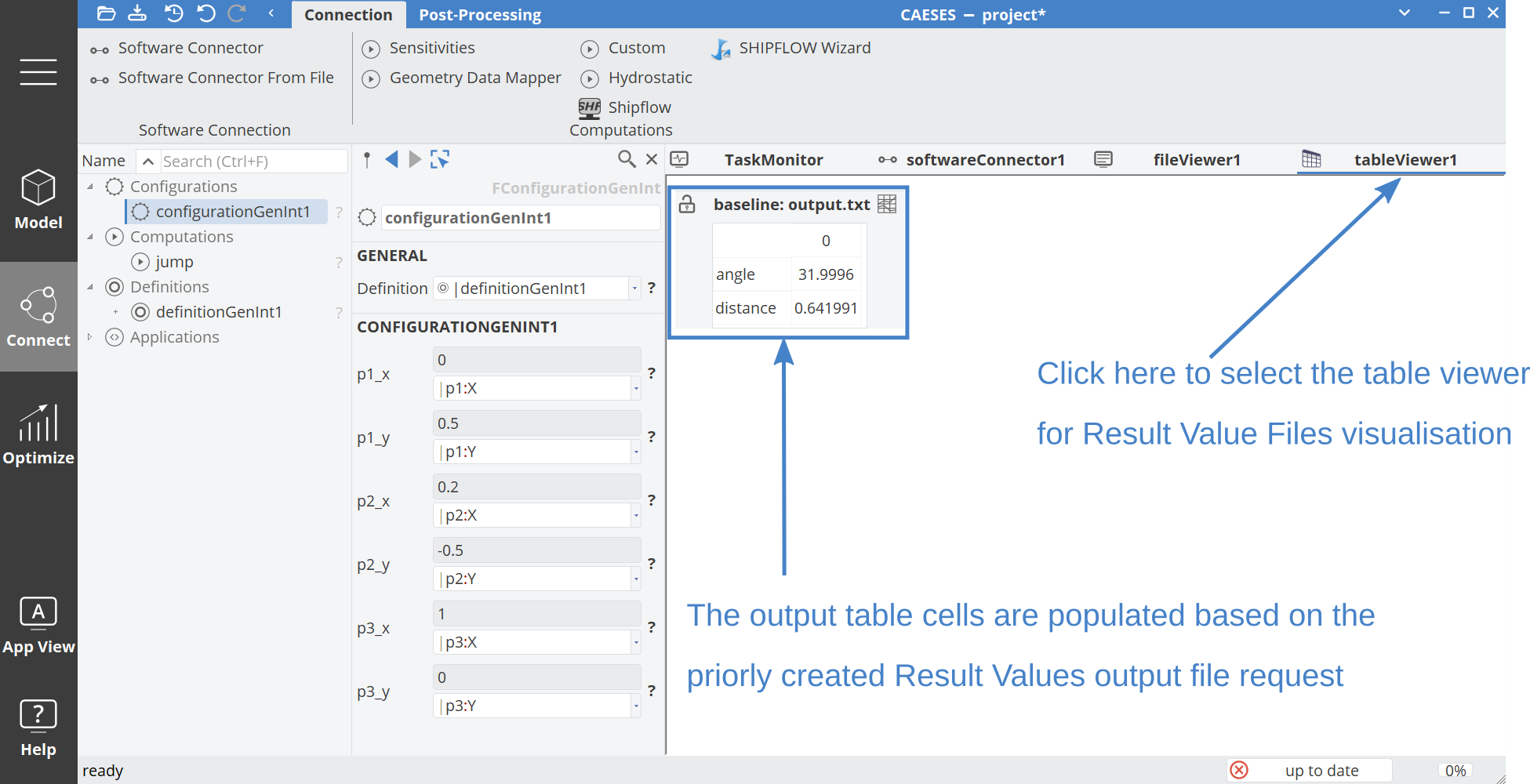
The external computation run that was triggered at the end of the last tutorial step should have completed by now. It is time to inspect the simulation results by having a look at the computed values and the PNG visualization. Select the tableViewer1 tab in the Connect workspace as shown below and have a look at the extracted simulation results.
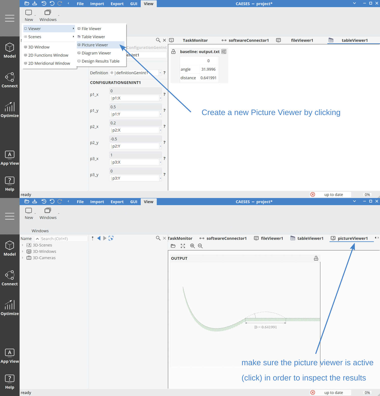
Now open the picture viewer in order to have a look at the imported PNG visualization. Do so by selecting the View tab of the Settings workspace, and create a new picture viewer. Then select the Picture viewer in the tab bar.
Optimization Setup
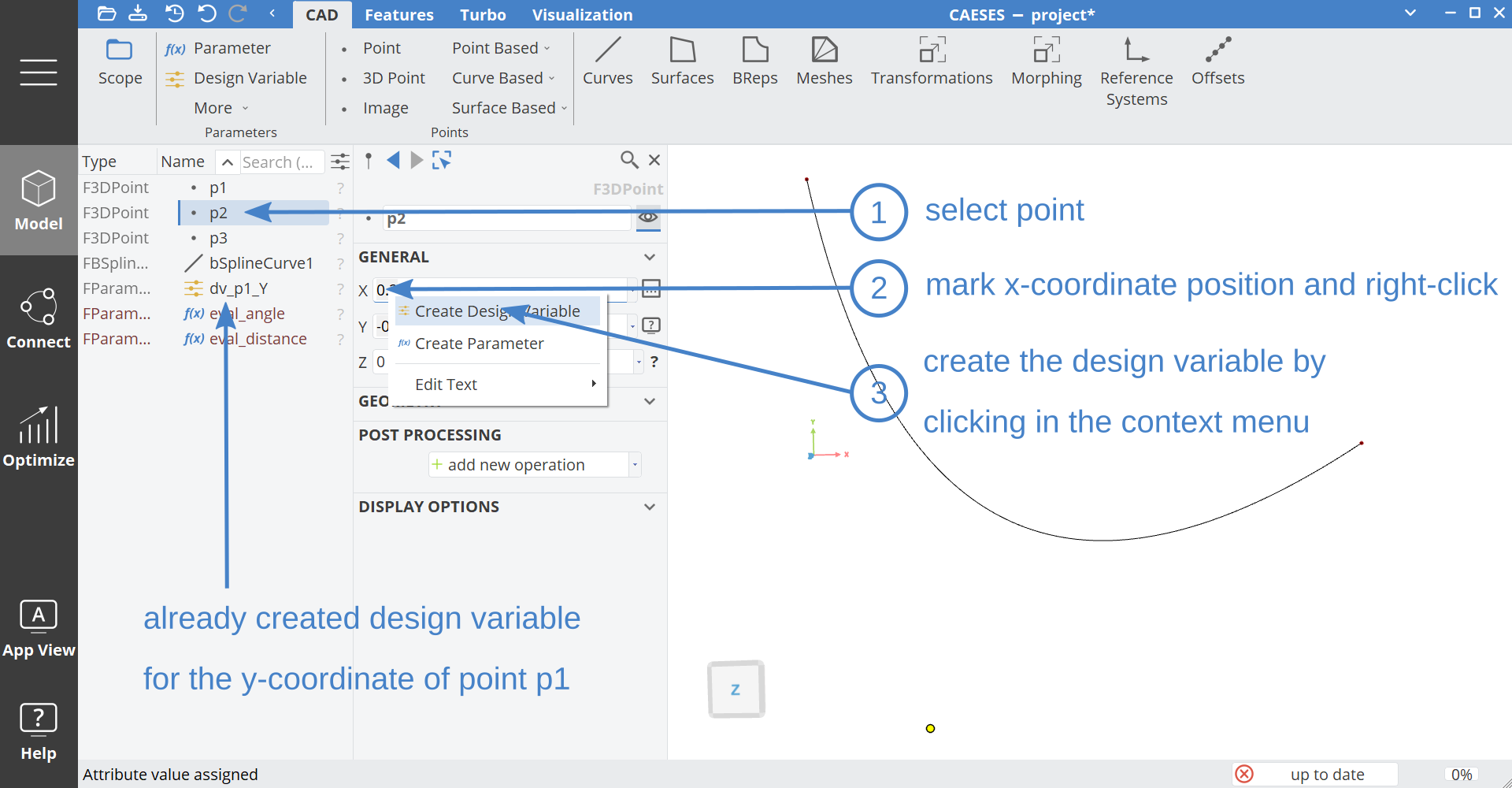
We now prepare the model for the optimization of the throwing distance by the systematic variation of the ramp geometry. In a first step we introduce design variables to parameterize the shape of the ramp. The process of introducing a design variable for the X-coordinate of point p2 is shown in the screenshot below. We also create a design variable for the Y-coordinate of p1 in the same way.
We now enter the Optimize workspace and create a new TSearch design engine as optimization procedure.
Add the created design variables to the design engine and set the valid range to [0,1] for both.
Then, add the evaluation parameters eval_angle and eval_distance in the design engine. Set the objective for eval_distance to "max". The objective for eval_angle is set to observer.
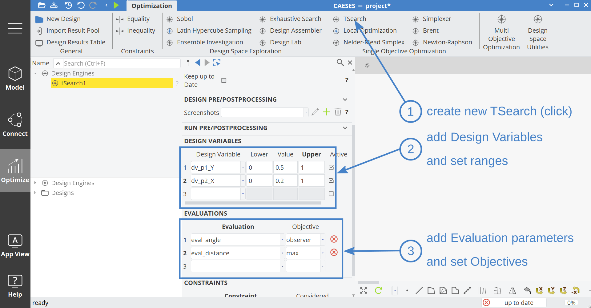
The optimization setup is now complete. By running the optimization process, the design engine will systematically vary the selected design variables of the model. The TSearch algorithm hereby varies the design variables with the aim to obtain a maximum value for the objective eval_distance. The objective eval_angle is not considered in the optimization process because it is set to "observer". The parameter is set to "observer" to show up in the optimization log for information purposes.
Optimization Run
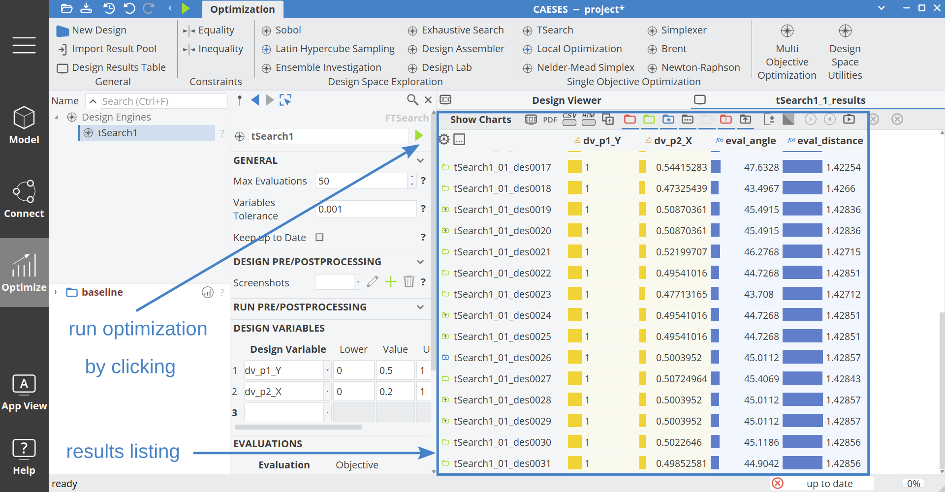
As the last step we invoke the optimization procedure which completes this tutorial. You can sort the eval_distance column by clicking on the header in order to find the best design.
CAESES Project File
If you want to take a look at the finalized parametric model you can find the resulting CAESES project file jumper.cdb here: