Introduction to Feature Programming
Any single action in CAESES is available as a command. For instance, the creation of geometries and the setting of their attributes are done via the graphical user interface, but for each of these actions there is a corresponding command triggered internally. These commands can be encapsulated and put together by the user in order to have complex or repeating command sequences ready to be executed with a single click (“macro”).
All of the possible commands are listed in the Type documentation. CAESES distinguishes between type and global commands : Type commands allow the creation of objects and the setting of object attributes. Global commands are not related to a specific type. Typical global commands are mathematical operations such as sin(), cos() and sqrt() etc.
Features can be utilized for user-defined functions with loops and if-statements, encapsulation of curve definitions for surface modeling ( Meta Surface ), reading and writing of ASCII files for proprietary data exchange, COM interfacing, and many other things where customization is required.
Feature Definitions
Features appear as objects in the object tree. They are based on an individual feature definition which holds the following information:
- Arguments: Input data for the feature (values, strings, points, curves, surfaces, ...)
- Create Function: User-defined command sequence that processes the input data
- Attributes: Output, i.e. resulting objects
Example: De Laval Nozzle
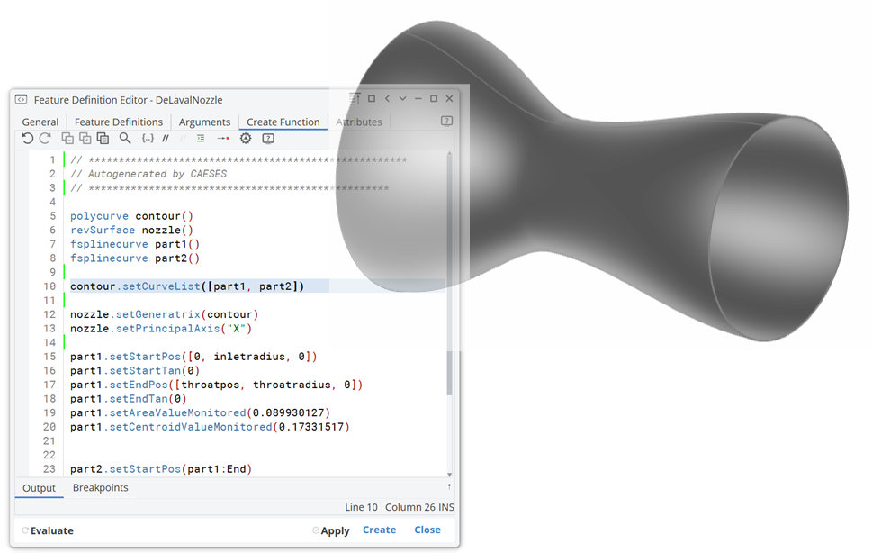
For a start, this tutorial shows how to create a simple Feature Definition from scratch: As an example, the De Laval Nozzle (also called convergent-divergent nozzle) is modeled first in a simplified manner and then encapsulated in a Feature Definition. A set of input parameters such as radius, length etc. finally controls the geometry. Such a custom geometry can be documented, re-used and even shared with other users of CAESES.
Nozzle Contour
The nozzle will be based on a 2D contour that gets rotated so that a surface of revolution is generated. We design the contour curve in a normalized system, e.g. the end position will be located at x = 1.

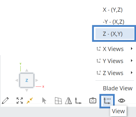
- Click on the z-face of the coordinate system cube in the 3D view in order to switch into the X-Y-view. Alternatively, choose the view button and click on Z-(X-Y) to rotate the view in the X-Y plane.
- Create an
F-Splinecurve via Model workspace > CAD tab > Curves category > Point based > F-Spline and call it “part1”. - Set the start position to
[0,0.3,0]and the start tangent to0degree. - Set the end position to
[0.4 ,0.15,0]and the end tangent to0degree.
This is the first part of the contour. Let’s continue with the second part:
- Copy and paste the first curve via Ctrl + C and Ctrl + V.
- Set the start position to be the end position of “part1”:
- Drag & drop the curve part1 into the Start Position field of part2
- add the expression
:endafterpart1to get the end point of the curve (|part1:end)
- Set the end position to
[1,0.25,0]. - Check if both tangents are set to
0degree.
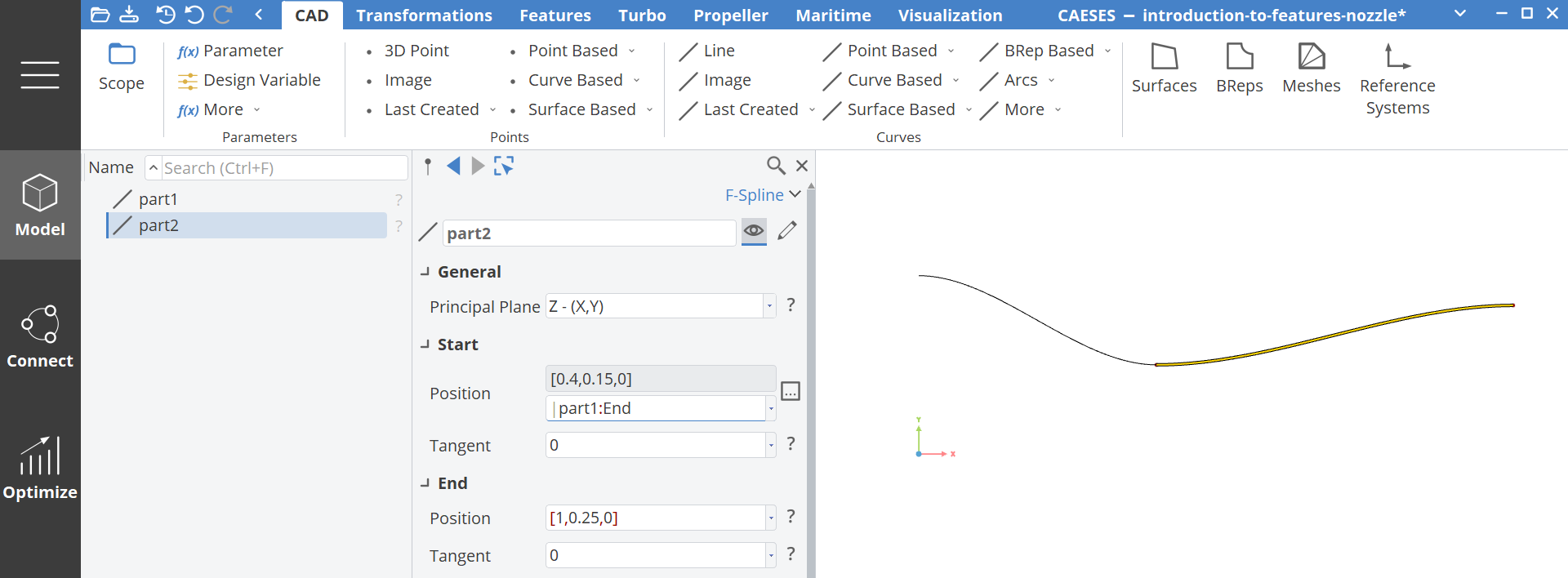
Now, we put the two parts together into a Poly Curve in order to have a single curve defined.
- Select the two curves i.e. first, select “part1” press and hold Ctrl and then select “part2”.
- While both curves are selected, choose CAD tab > Curves category > Curve Based > Poly and call the new curve “contour”.
Nozzle Surface
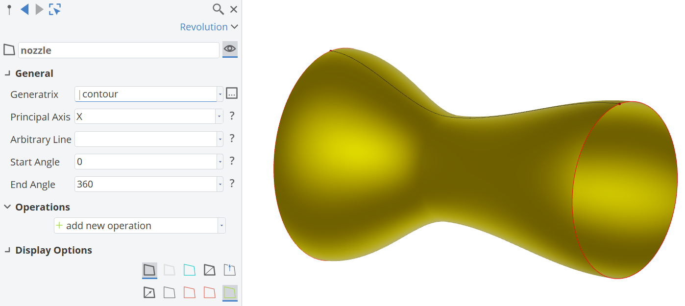
Based on the single curve “contour” we can now create a surface of revolution:
- Choose CAD > Surfaces > Curve Based > Revolution.
- Set the name to “nozzle”.
- Set “contour” as input for Generatrix.
- Set the Principal Axis to
X. - The default start angle
0and the end angle of360degrees should be set automatically.
Parameters
Before we create a Feature Definition from this basic model, let’s introduce some parameters which will be the input for the feature:
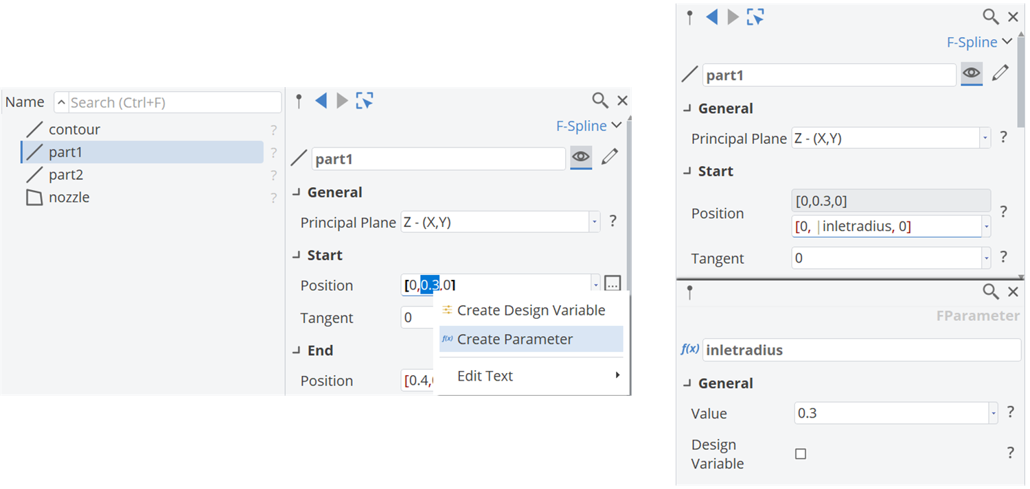
- Select part1 and create a parameter for the y-value (
0.3) of the start position:- Mark the value and choose from the context menu via right mouse click Create Parameter.
- Set the name of the new parameter to “inletradius”.
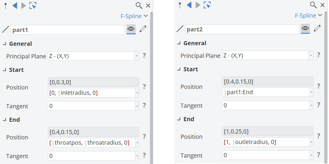
- For the end position of part1, create two more parameters for the x- and y-value in the same manner. Call the x-parameter “throatpos” and the y-parameter “throatradius”.
- For the end position of part2, create a final parameter for the y-value and call it “outletradius”.
Feature Definition from Selection
In this step we will put the nozzle in a modular Feature Definition. Anything that will be encapsulated needs to be selected:
- Select all 4 geometry objects (holding the Ctrl key) but not (!) the 4 parameters – these will not be part of the upcoming Feature Definition, but will be used as arguments for input.
- From the context menu (right mouse button), choose create feature definition.
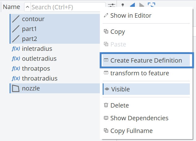
The context menu is a short cut – there is an entry in the ribbon in the Features tab as well.

Feature Definition Name
The Feature Definition Editor of our new definition opens automatically after creating a feature from selection. Basically, the definition is ready for use but we will modify it slightly:
- First of all, click on the General tab of the dialog and set the Type Name to “DeLavalNozzle”.
- For the attribute Label , we enter a more readable name using spaces.
- Press the Apply button (at the lower right corner) so that these first changes are applied to the definition.
- Close the dialog. We will have a look at it again in the next steps.
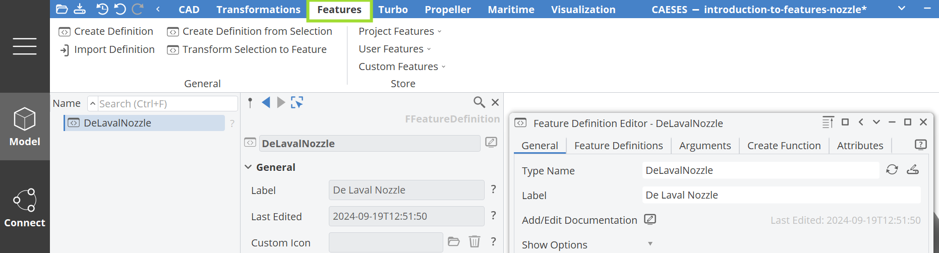
The Feature Definition can be found in the Features Tab.
Create a Feature from the New Definition
The Feature Definition itself is only an abstract description, similar to a template or macro definition. It is stored in the project and can be accessed in the Features tab. It can also be exported for use in other projects. We will now create an object (instance) that is based on our Feature Definition and creates an object in the object tree of the CAD tab:
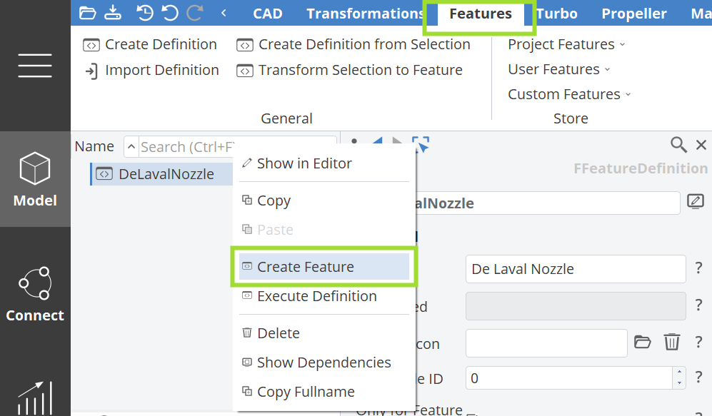
- In the Features tab, right-click on the Feature Definition “DeLavalNozzle” in the tree and choose Create Feature from the context menu.
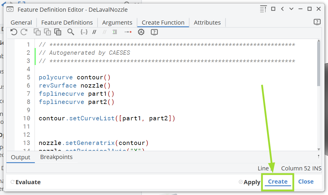
You can also directly create a feature object (instance) by clicking the Create button in the Feature Definition Editor.
Switch back to the CAD tab to see the created feature object (instance of the feature).
A new feature DeLavalNozzle1 gets created in the tree. Since the new feature and the initial geometry are coincident, we want to hide the initial geometry for the time being.
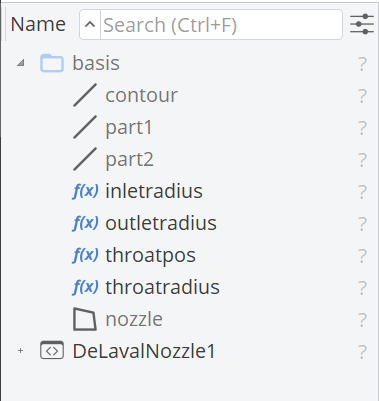
- Select all the geometry and parameter objects apart from the new feature DeLavalNozzle1 and choose CAD > Scope. (All objects should be sorted into the scope. If you missed one object, just drag and drop it into the scope.)
- Set the name of the new scope to “basis” and set it invisible by clicking on the scope icon left of the name “basis” in the tree.
Now, only the feature DeLavalNozzle1 is visible in the 3D view.
- Change the input parameters slightly in order to test your feature output.
Alternatively, project feature definitions can also be accessed via the Features tab > Project Features. Try it out and choose create from the upcoming dialog. Try out the dialog’s button execute as well: The definition is only executed once and all created objects are given in the tree (we refer to it as “transient” execution, no feature object is then available in the tree).
Input Arguments
Next we will modify the arguments of the Feature Definition to customize the feature input interface and to have more readable input names.
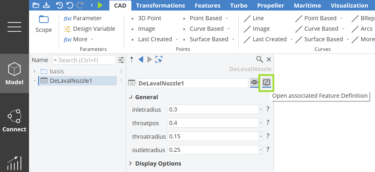
- Select the feature DeLavalNozzle1 and click on the icon in the upper right corner of the editor.
This is a short cut and it always opens the associated Feature Definition (which in our case is “DeLavalNozzle”). Alternatively, double-click on the definition DeLavalNozzle in the tree of the Features tab.
- Let's structure the input arguments. Go to the tab Arguments in the Feature Definition Editor
- Set category names for inlet, throat and outlet.
- Set labels to the input arguments.
- Press the Apply button.
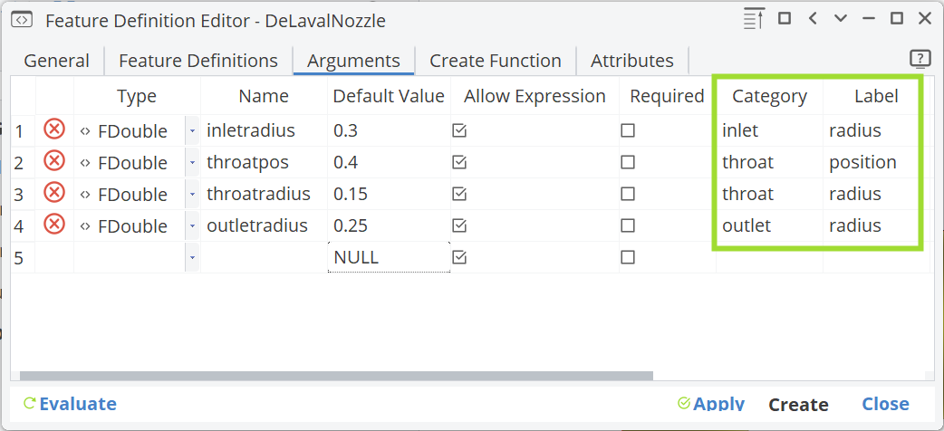
Setting a category and label for each input argument creates more readable names and a better interface structure.
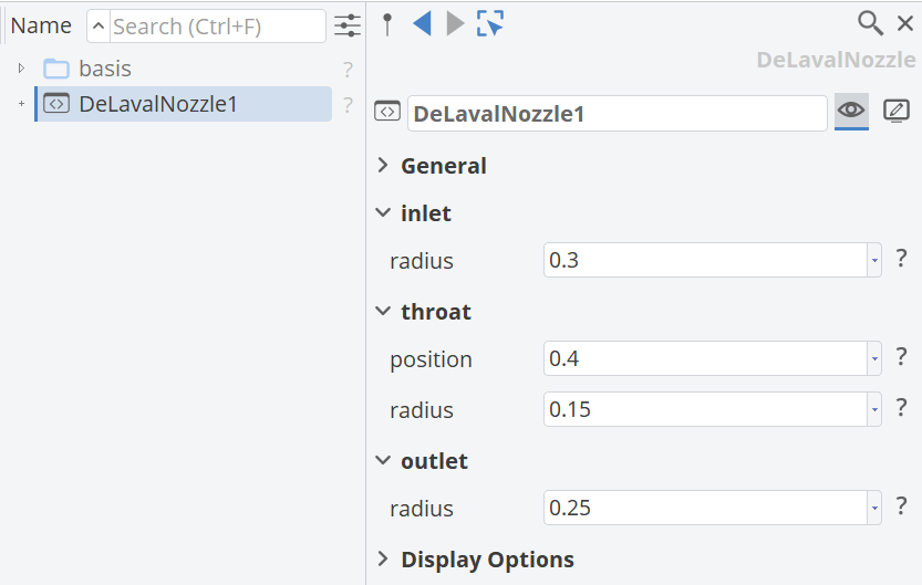
Attributes
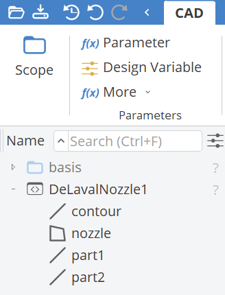
In our case, the attributes of this definition are the contour curves and the final nozzle surface of revolution. Here are some explanations:
- Expand the feature DeLavalNozzle1 in the tree to see all attributes.
- In the Feature Definition dialog of DeLavalNozzle, go to the Attributes tab and make only the surface
|nozzleaccessible (✓). - Press the apply button.
- Take a look at DeLavalNozzle1 again: only the nozzle surface is now accessible in the tree.
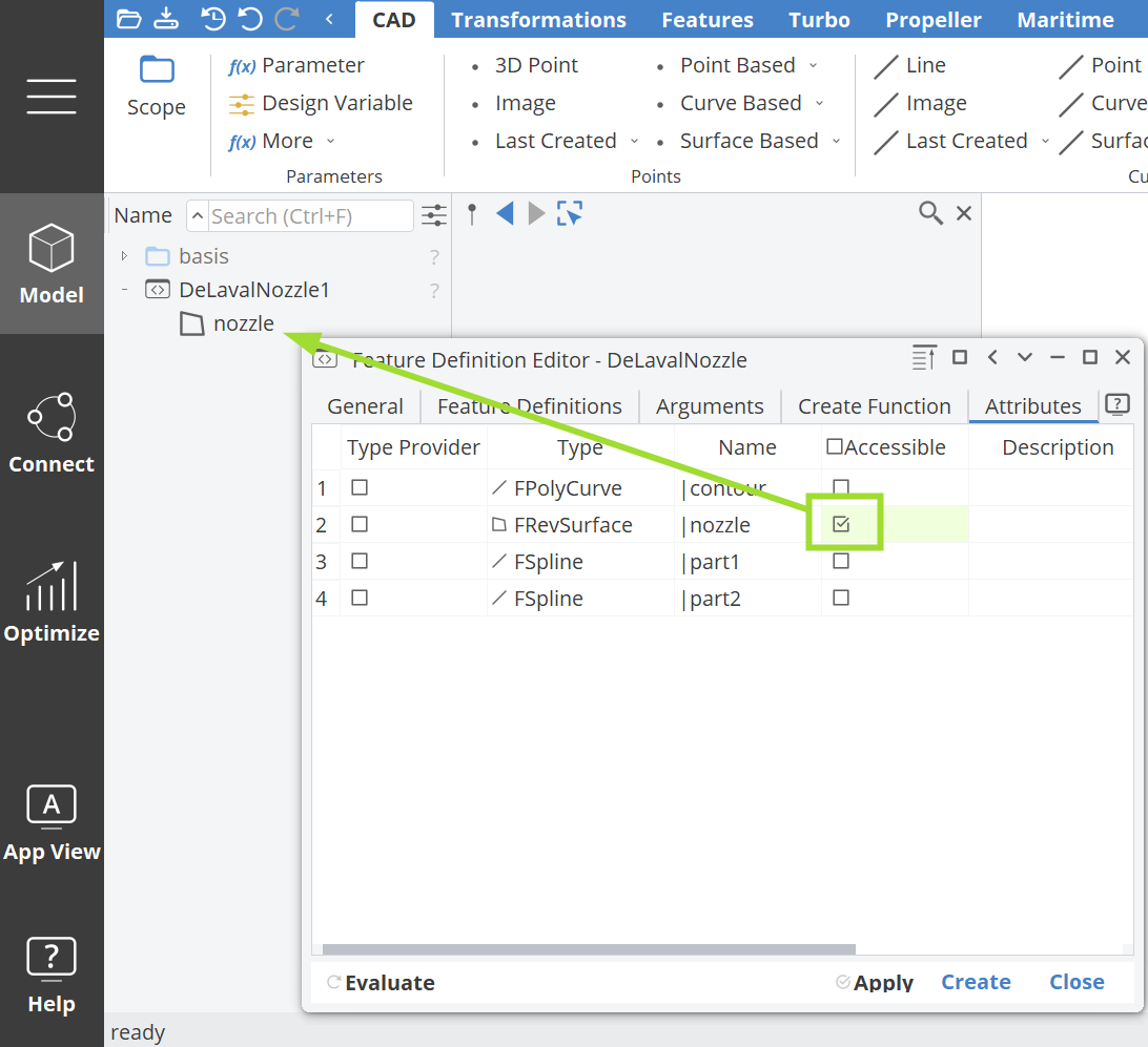
Accessibility is helpful if many auxiliary attributes are created and given in a definition. These attributes can be “switched off” so that only relevant results are visible and accessible. In the header of tab Accessible (in the Attributes tab) , you can check/uncheck (✓) all attributes at once. Accessible attributes can be further utilized in subsequent modeling processes such as using drag and drop to connect the nozzle surface to other objects outside of the feature. For instance, if you want to set the nozzle as
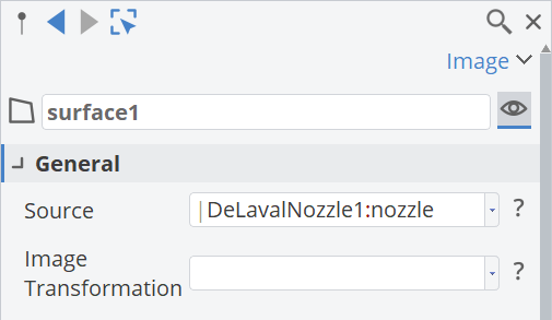
input for an image surface (CAD tab > Surfaces > Surface Based > Image), the source contains DeLavalNozzle:nozzle.
A First Look at the Command Sequence
The command sequence, given in the tab Create Function of the Feature Definition Editor, describes the process based on the input arguments.
- Click on the tab Create Function of the Feature Definition DeLavalNozzle.
The first block calls default creator commands such as the one of type FPolycurve. The
command polycurve is followed by the name of the new object and parentheses, for instance contour(). Creators can be called anywhere in the definition, not necessarily at the beginning.
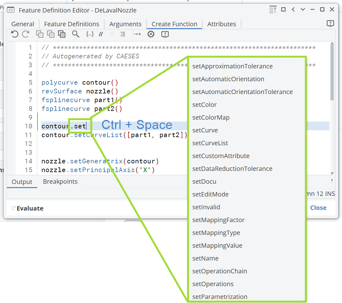
This command sequence can also be written manually and modified by simply changing it. Typically, auto-completion is used for syntax support:
For instance, contour.set + Ctrl + Space provides the list of commands starting with set, see the screenshot below.
Documentation
Let’s add some documentation to the Feature Definition which is helpful if things are getting more complex or, for instance, if you want to recall the exact meanings of a larger set of input arguments after a while. Here is an example:
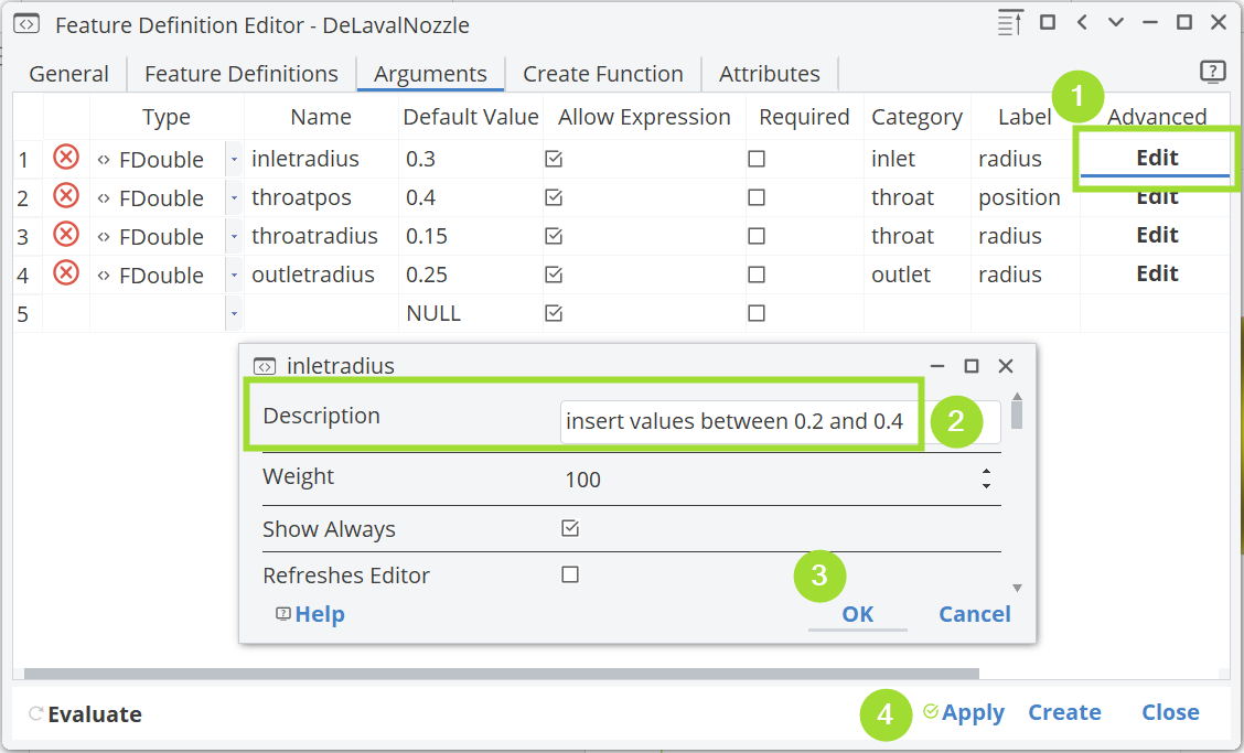
- In the Arguments tab list of input arguments, click the Edit button of the Advanced column of e.g. “inletradius”.
- Add a short description for this input argument in the Description field.
- Close the dialog by clicking the OK button.
- Optionally, do this for the other arguments as well.
- Press the Apply button and close the Feature Definition dialog.
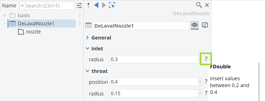
- Click on the help icons (?) of the feature argument to see your argument documentation.
Export
Finally, the definition can be exported in order to re-use it in other projects, e.g. for recurrent tasks.
- In the Feature Definition ( General tab), click on the Export button in order to save the definition as a
.fdffile.
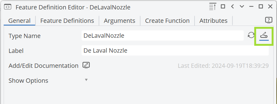
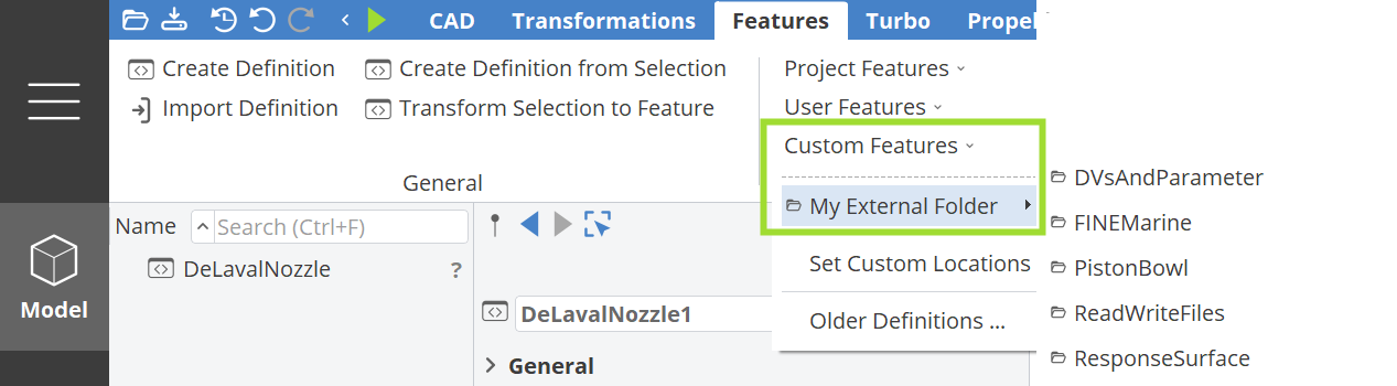
By default, the CAESES user directory is the target export directory but you can create subfolders in your user directory which will also be shown in the ribbon.
You can now access and import the definition again via the Features tab > Store > User Features.
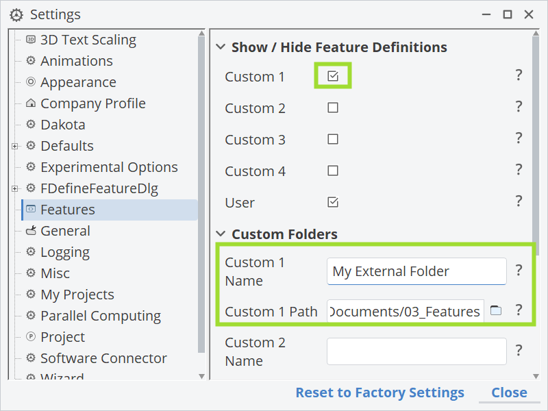
Involve your own directories: Open the settings via Menu > Settings > and click on Features. Activate the toggle of custom 1 and add a name as well as a path to your feature definitions.
Conclusion
This has been a first introduction to Features. Basic information is provided about the general structure of feature definitions. A persistent feature gets created based on a definition and the input can be changed manually. Documentation is added to feature arguments as well as to the definition, which is helpful when the feature gets more complex.
Advanced Users
This definition was created from a selection of objects in the tree. For advanced users, the next tutorials show how to write your own custom definitions using control statements like loops and if-else-cases etc., for which automatic creation from selection is not available. You will also learn more about auto-completion that helps you when writing definitions.
You can find a brief reference of possibilities in the type documentation for FFeatureDefinition
Features also play a major role in the context of fully-parametric modeling of complex free-form surfaces. See the Meta Surface tutorial for more information.
CAESES Project File
If you want to take a look at the finalized model you can find the resulting CAESES project file introduction-to-features-nozzle.cdb here:
Video Tutorials
If you would like to learn more about features in short video tutorials, check out our CAESES Video Platform.
CAESES Video Platform