Intake Port Modeling
This tutorial gives you an overview on how to model a symmetric intake port with a pent roof cylinder head in CAESES.
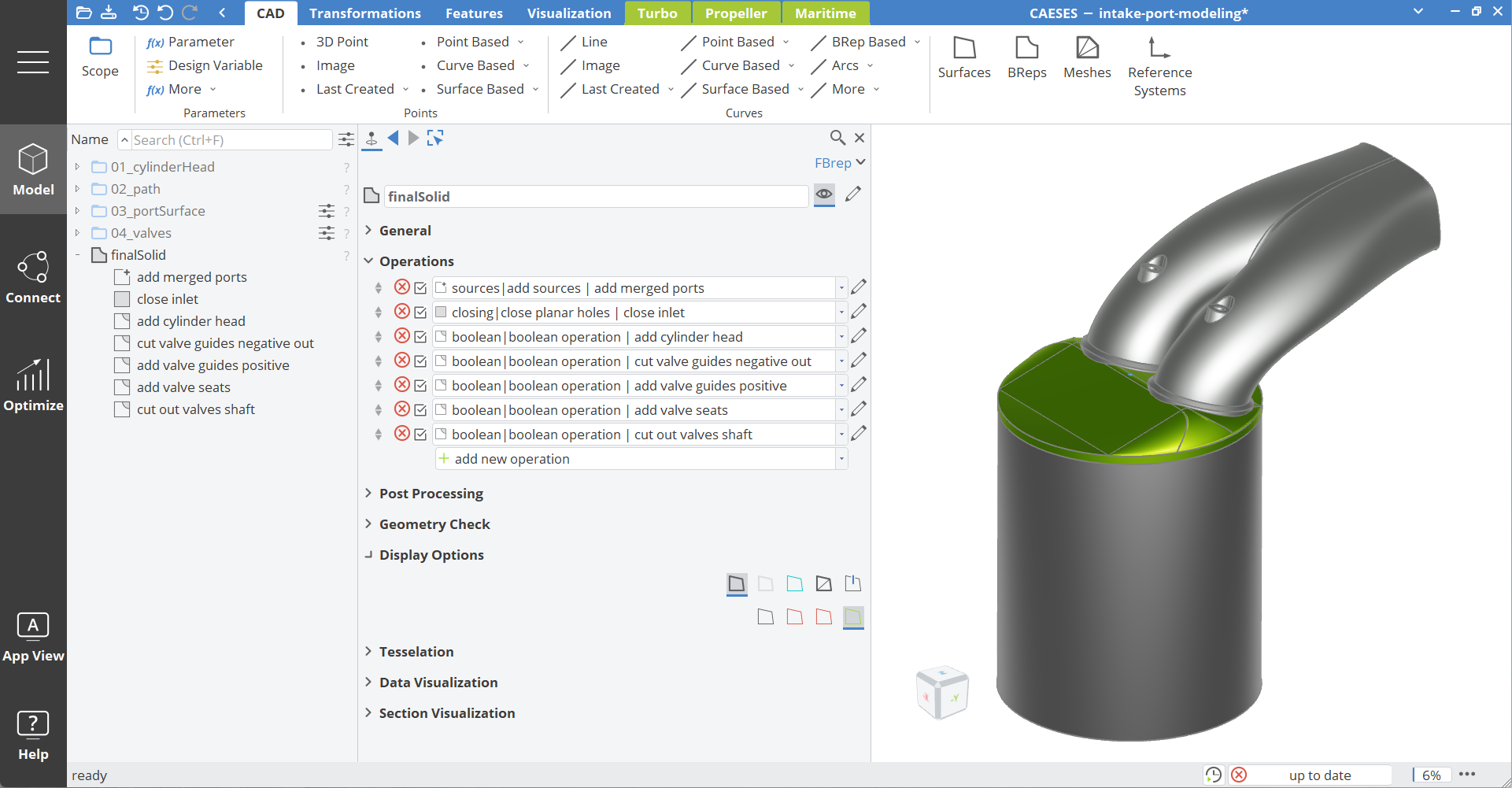
Before diving into this best practice for intake port modeling we recommend going through the basics of geometry modeling with CAESES. The tutorial First Modeling Steps is a pre-requisite for this tutorial.
Cylinder Head
In the first step we model a pent-roof cylinder head.
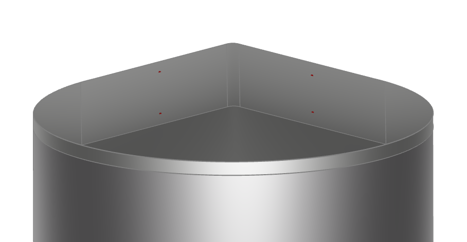
Folder Structure
Let's create some folders (also called scopes in CAESES) in order to organize our objects.
- Create a scope via Model workspace > CAD tab > Scope. Rename this scope to "01_cylinderHead".
- With the middle mouse button mark this scope as your working scope. The scope icon will turn green and all newly created objects will be placed inside this scope.
- Create a new scope and rename it to "parameters".
- Create a new scope and rename it to "setup".
Pre-Configured Cylinder Head
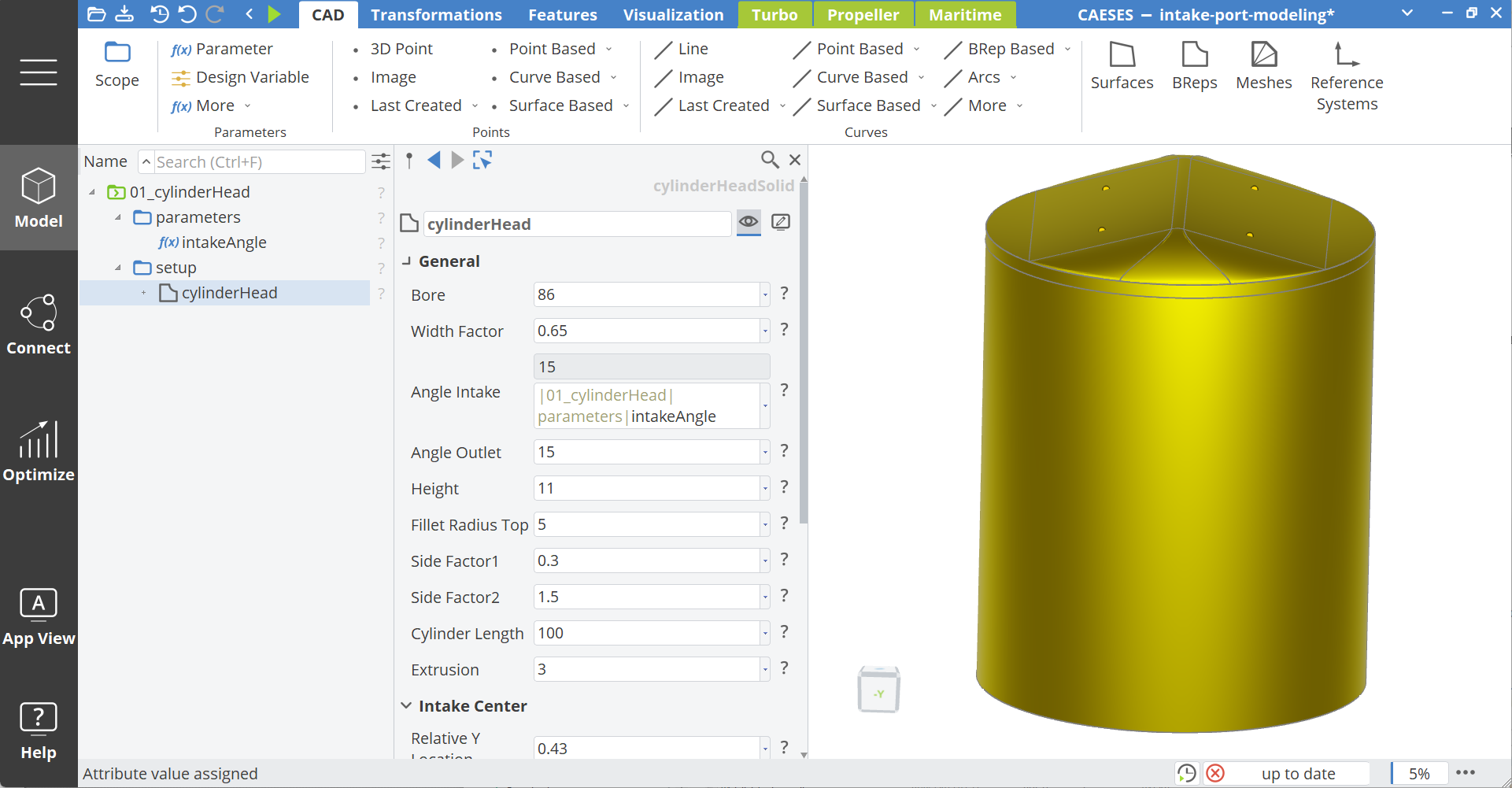
In this tutorial we will use a pre-configured cylinder head, which is created using the following feature definition. Get the feature definition and add it to you project. You will find the feature definitions in the Model workspace > Features tab after the import.
Get Cylinder Head Feature- Right click on the cylinderHeadSolid feature definition (in the Features tab) and choose Create Feature. In the CAD tab, set the name of the new feature instance to "cylinderHead".
- Move cylinderHead to the folder 01_cylinderHead|setup (drag and drop it).
- Select the feature cylinderHead.
- Select and right-click the value of the argument Angle Intake and create a new parameter with the name "intakeAngle".
- Drag and drop the parameter intakeAngle into the parameters scope.
Path
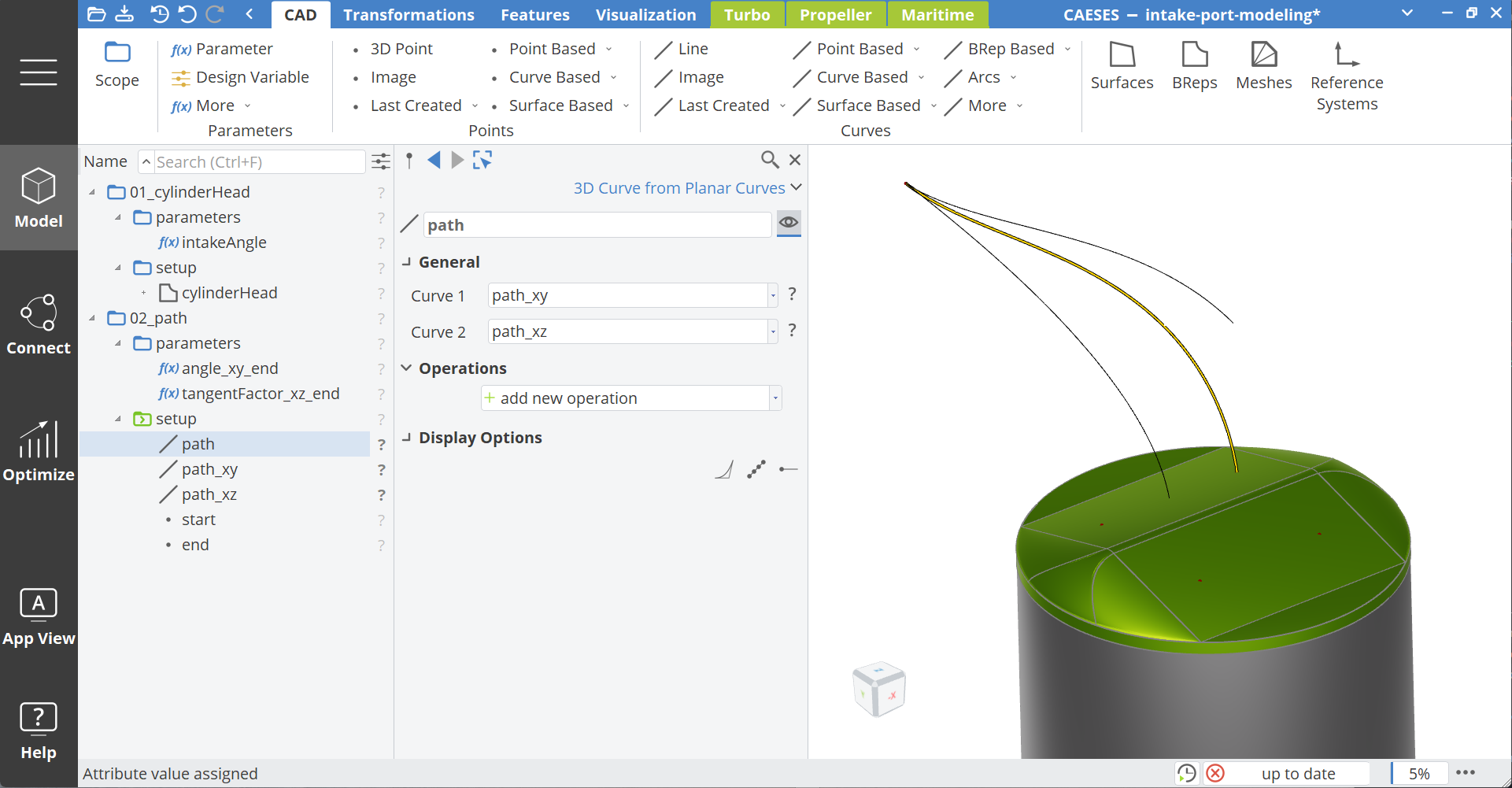
The port surface will be swept along a path like shown in the tutorial First Modeling Steps For a detailed control, we will create two 2D paths which we combine to a 3D path afterwards.
-
Click with the middle mouse button into the empty space of the object tree to deactivated the 01_cylinderHead (green icon) working scope
-
Create a folder with the name "02_path" (in the same level as the scope
01_cylinderHead). -
Inside that folder create the folders parameters and setup.
-
Make
02_path|setupyour working scope by clicking on it with the middle mouse button. -
Create a new 3D Point (via Model workspace > CAD tab > Points category > 3D Point ) with the name start.
- Set X:
110 - Set Y:
0 - Set Z:
45
- Set X:
-
Select the point centerIntake1 from the cylinderHead feature. You can do this for example in the 3D View.
-
Create a new Image Point via CAD* workspace > Points category > Image and set the name to "end".
-
Create a new curve via CAD > Curves > Point Based > Planar with Tangent Control and set the name to "path_xy".
-
Set the arguments as:
- Start Position:
startpoint - Start Angle:
180 - End Position:
[end:x,end:y,start:z](Remember to use the Alt key to link objects) - End Angle:
180 + -11 - End Tangent Factor:
0.5
- Start Position:
-
Mark the
-11from the End Angle and create a new parameter for it. Set the name to "angle_xy_end". -
Move this parameter to the parameters scope per drag and drop.
-
Create a new curve via CAD* > Curves > Point based > Planar with Tangent Control and set the name to "path_xz".
-
Set the arguments as:
- Principal Plane:
Y - (Z,X) - Start Position:
startpoint - Start Tangent Control:
false(deactivate box) - End Position:
[end:x,0,end:z] - End Angle:
180 + |01_cylinderHead|parameters|intakeAngle(from the parameters of the cylinder head)
- Principal Plane:
-
Create a parameter for the End Tangent Factor and set the name to "tangentFactor_xz_end".
-
Move this parameter to the parameters folder.
Now we can combine both 2D curves into a 3D curve.
- Select the curves path_xy and path_xz (multi-select via Ctrl key)
- Create a new curve via CAD > Curves > Curve based > 3D Curve from Planar Curves and set the name to "path".
Port
In this section we will model the port as a simple lofted surface through three sections. This approach is based on the tutorial First Modeling Steps, which is a pre-requisite for this intake port tutorial.
Sections
We will simply copy the content of the tutorial First Modeling Steps into our current project.
- Open a second instance of CAESES.
- Open the tutorial First Modeling Steps.
- Open the finalized CAESES project file
first-modeling-steps.cdb
Let's copy the relevant profile section from the First Modeling Steps duct into the current intake port project.
-
In the current intake port project, create a new folder with the name "03_portSurface".
-
In the project from the tutorial First Modeling Steps
- select the folder 02_profileStart
- copy the folder via Ctrl+C
-
In the current project select the folder 03_portSurface and paste the folder (via Ctrl+V) from the other project here.
-
Rename 02_profileStart to "section1".
Next we have to set the path on the profile curve profile.
- Add a Sweep transformation operation to the profile curve
- Move the cursor into the path argument and select the object path from 02_path by using the ALT-key
- Set the sweepPos parameter in the field Path Parameter
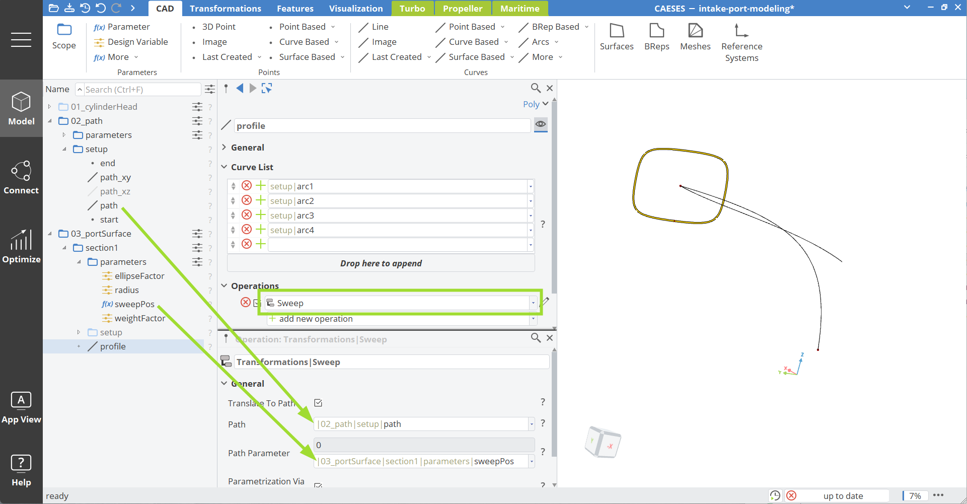
We want to define three sections for the intake port. Therefore, we reuse the section and adapt the parameter values afterwards.
- Copy and paste the scope section1 twice. (The copied scopes will be renamed to section2 and section3 automatically.)
Now let's adjust the parameter and design variable values of the single sections.
- CLick on the slider icon to the right of the 03_portSurface scope to see an overview of the design variables.
- Activate the Show Parameter (f(x) icon) and Edit (pencil icon) filters by clicking on the icons
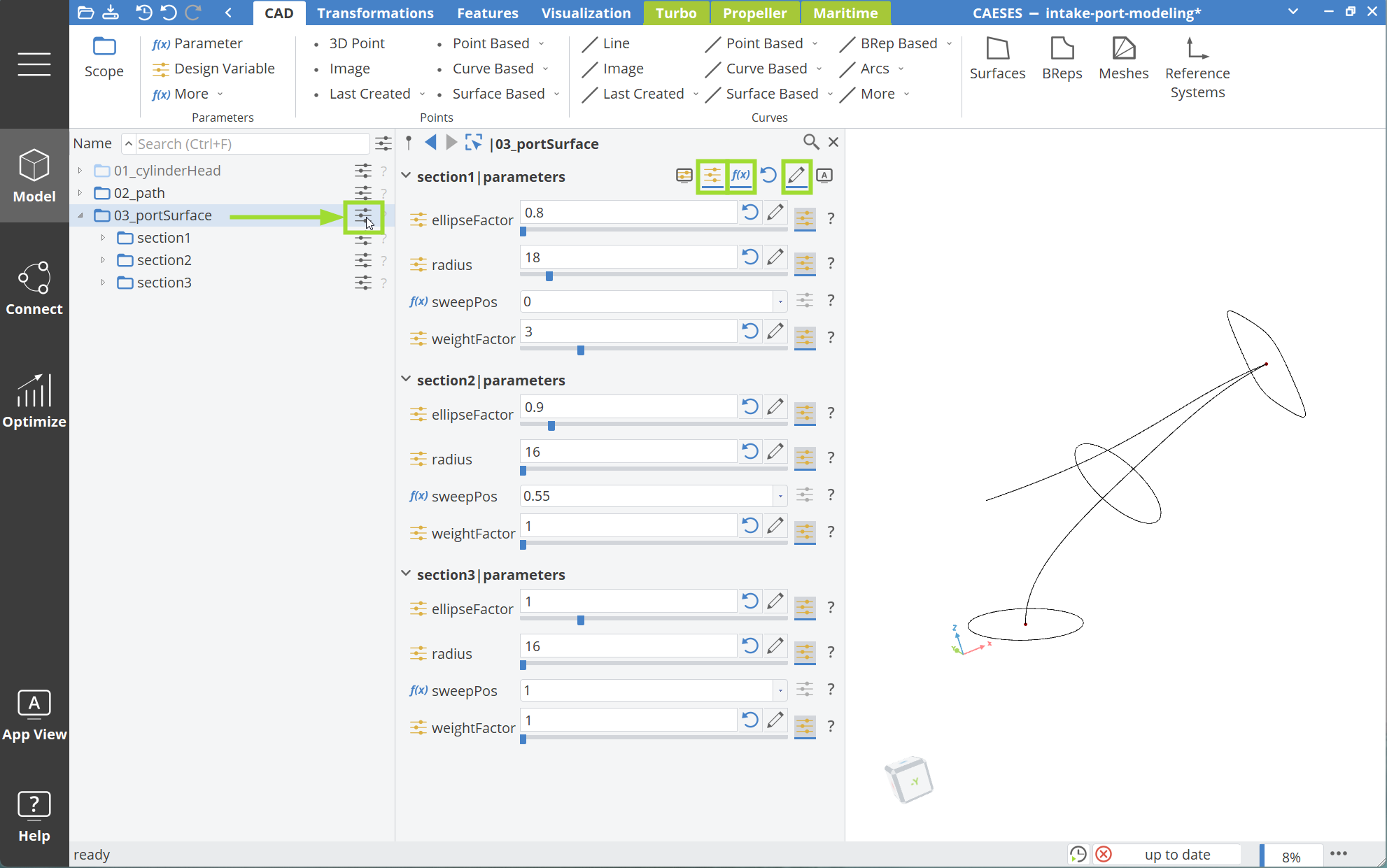
- Set the values according to the following:
- Section 1:
- Ellipse Factor:
0.8 - Radius:
18 - SweepPos:
0 - WeightFactor:
3
- Ellipse Factor:
- Section 2:
- Ellipse Factor:
0.9 - Sweep Position:
0.55 - Radius:
16 - SweepPos:
0.55 - WeightFactor:
1
- Ellipse Factor:
- Section 3:
- EllipseFactor:
1 - Radius:
16 - SweepPos:
1 - WeightFactor:
1
- EllipseFactor:
Port Surface
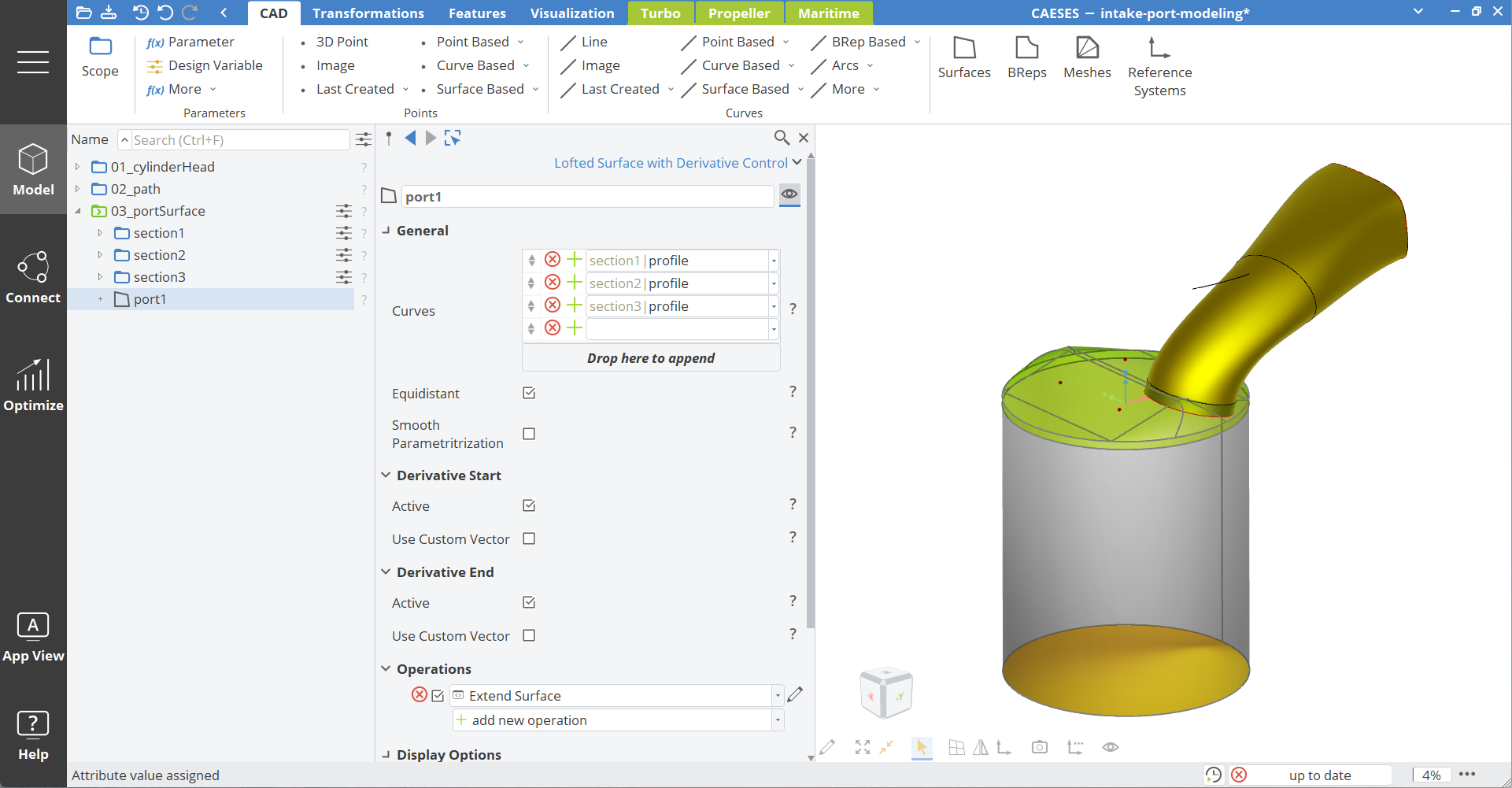
The port surface is created by a loft through the three sections.
- Select the curves with the name profile in each section scope. You can use multi-selection by holding the CTRL button. The order of selection is important, so start by selecting the profile in scope section1, followed by profile in section2 and section3.
- While all three profile curves are selected choose Surfaces > Curve based > Lofted Surface with Derivative Control
- Activate the box Equidistant in the newly created surface
- Set the name of the lofted surface with derivative control to "port1"
- Move the lofted surface via drag and drop into the scope 03_portSurface
For later trimming steps, we need the surface to extend a little bit.
- Select the surface port1.
- Add an operation to extend the surface via add new operation > More > Extension
- Set the V Domain Max to
0.05
The setup should look like this now:
Mirror Port
Now we mirror the first port to create the second port.
- Select port1.
- Create an Image Surface via CAD > Surfaces > Surface based > Image and set the name to "port2".
- Add a new Scaling operation via add new operation > Transformations > Scaling.
- Set the Scaling Y-value to
-1.
The merging of the two port surfaces is done with a feature definition, which can be added here:
Get Merge Ports FeatureYou will find the feature definitions in the Model workspace > Features tab.
- Go to the Features tab in the ribbon
- Right-click on the Feature Definition (in the Features tab) mergeAsymmetricPorts and choose Create Feature
- Set the name of the created feature instance (in the CAD tab object tree) to "portsMerged".
- Set the port1 and port2 in the corresponding input fields
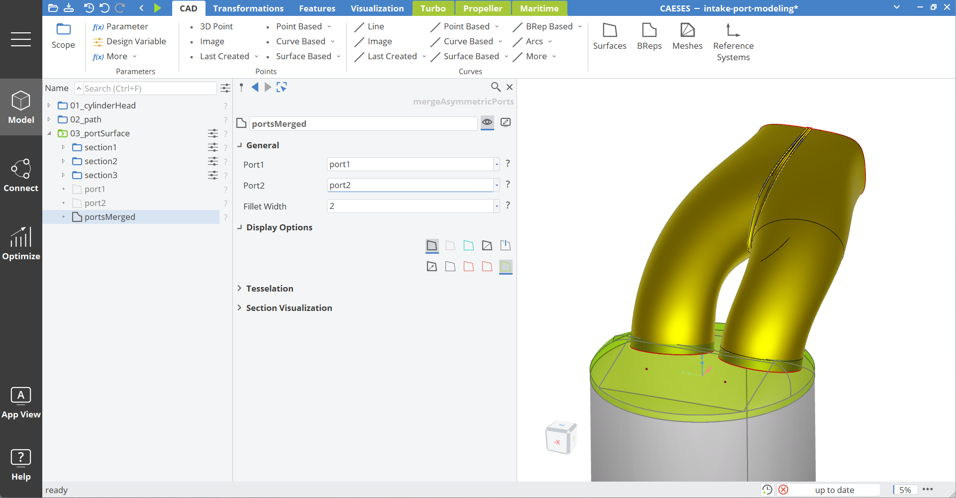
You can change the size of the fillet between the two ports with the argument Fillet Width.
Valves
In this step we will model the valve guides and the valves itself.
Valve Guides
- Create a new scope named "04_valves".
- Inside this scope create a new scope with the name "01_valveGuides".
- Make this scope the active working scope by clicking on the scope icon with the middle mouse button (a green scope icon indicates the active working scope).
- Select the center point end from the scope, where you created the path.
- Create an Image Point via CAD > Points > Image and set the name to "centerReference".
- Duplicate this point by copying and pasting this point into the same directory and set the name to "centerDirection".
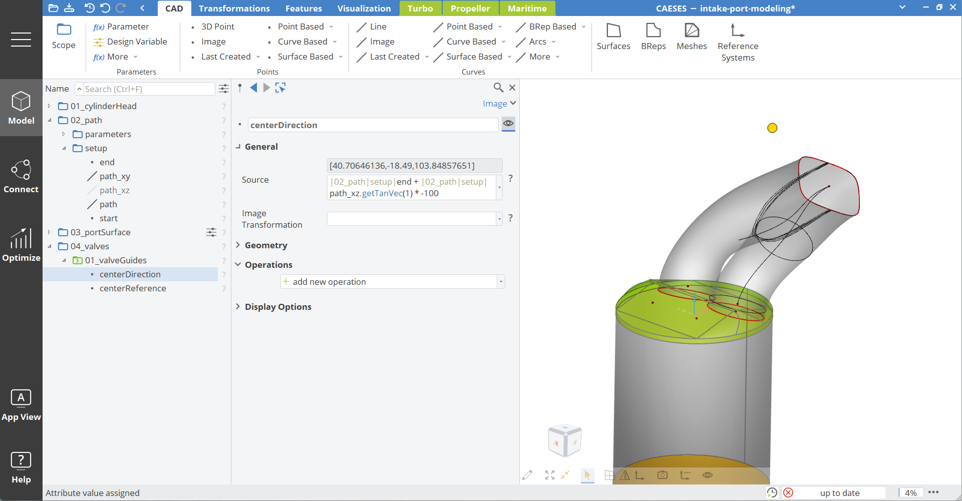
Now we will translate this point in direction of the path end by using the command .gettanvec(t) to get the normalized tangent vector at the position t (ranging from 0 to 1) of the path.
- Modify the Source argument of centerDirection to
...|end + ...|path_xz.gettanvec(1)*-100
- Select centerReference and centerDirection
- Create a line via CAD > Curves > Point based > Line and set the name to "dirLine".
- Select dirLine
- Create a new Circle via CAD > Curves > Arcs > Circle and set the name to "circle1".
- Set the radius to
4.
You can see that the option Axis Modeling is activated now. This means the circle is placed normal to the line dirLine.
We can also set the elevation.
- Duplicate circle1 with Ctrl + C (copy) and Ctrl + V (paste). This will set the name to "circle2" automatically.
- Set the Elevation to
30. - Right click on the
30to create a new parameter. Set the name to "valveGuideHeight". - Duplicate circle1 (it should set the name to circle3 automatically).
- Set the Elevation of circle3 to
100.
Now we can connect the circles with ruled surfaces.
- Select circle1 and circle2.
- Create a ruled surface via CAD > Surfaces > Curve Based > Ruled and set the name to "ruled1".
- Select circle2 and circle3
- Create a ruled surface via CAD > Surfaces > Curve Based > Ruled and set the name to "ruled2".
In order to convert the surfaces to a solid we create a BRep from it.
- Select ruled1.
- Create a BRep via CAD > BReps > BRep and set the name to "valveGuide1_positive".
- Add the new operation Closing > close planar holes.
The BRep valveGuide1_positive should be a close solid now (greyed BRep icon in the object tree). Do the same for the other surface:
- Select ruled2.
- Create a BRep via CAD > BReps > BRep and set the name to valveGuide1_negative.
- Add the new operation close planar holes.
We need these guides also on the other side.
- Select valveGuide1_positive and valveGuide1_negative
- Duplicate them via copying and pasting.
- Set the names to "valveGuide2_positive" and "valveGuide2_negative".
- Select one of the new BReps.
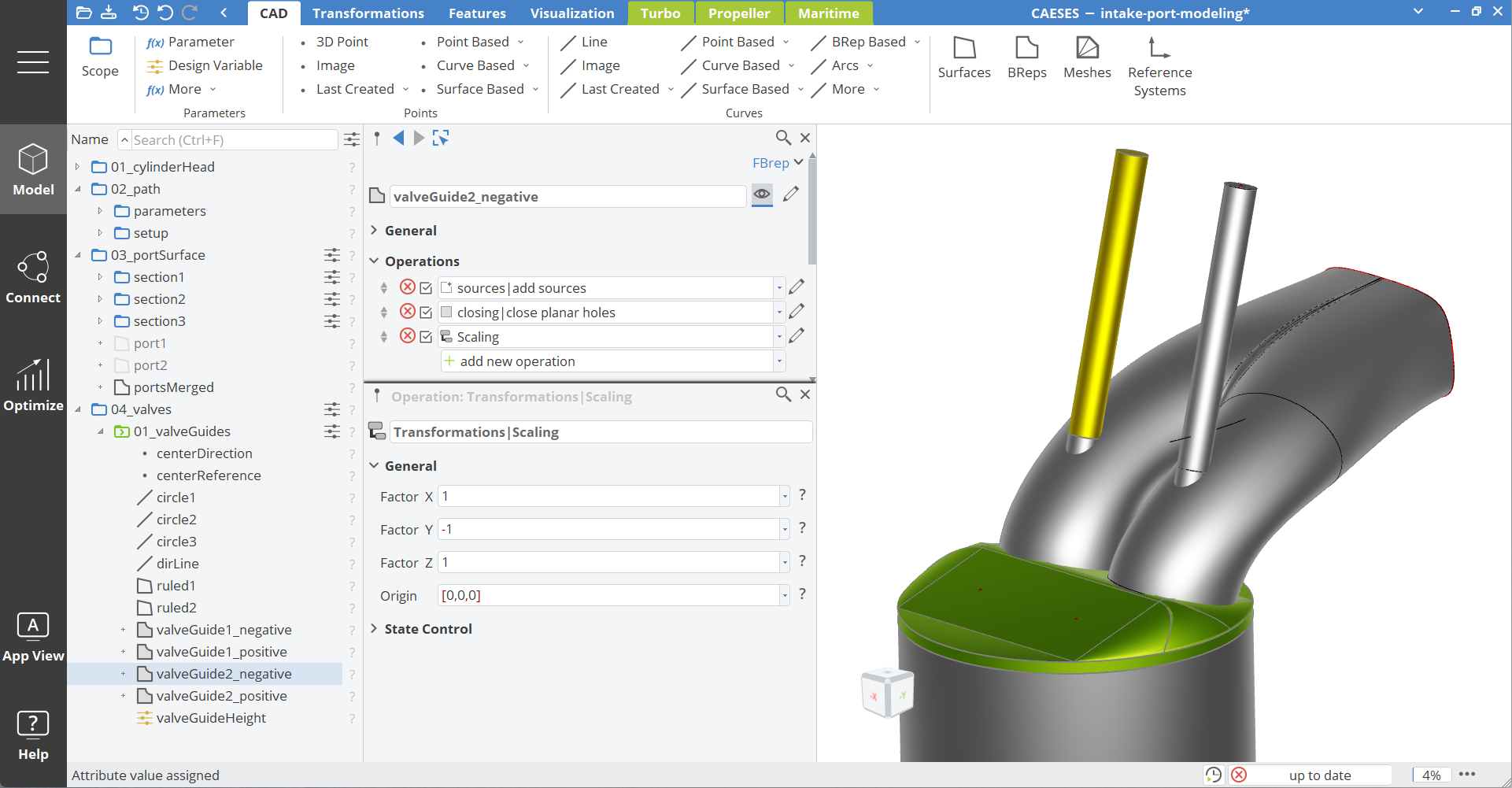
- In the Operations category of the BReps create a new Scaling transformation (Transformations → Scaling).
- Set the Y-Factor of the scaling transformation to
-1. - Do the same for the second BRep.
Valves
The valves are created with a feature, which can be added here:
Get Valves Feature- Create a new scope in 04_valves and set the name to "02_valves".
- Make 02_valves the working scope.
- Create the Feature Definition intakePortValves_class1 and set the name to "valves".
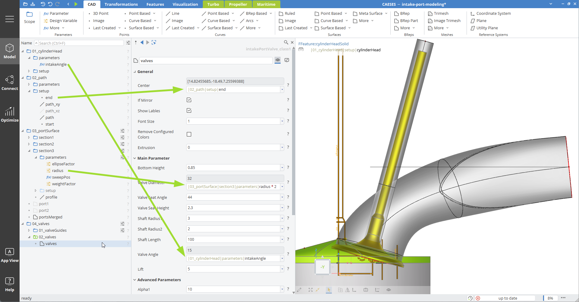
- Drag and drop the center point end from the scope of the path to the Center argument of the feature valves.
- Set the other arguments to:
- Valve Diameter: use the parameter
radius * 2from the 03_portSurface|section3|parameters - Shaft Radius 1:
3 - Shaft radius 2:
2 - Valve Angle: Use the parameter
intakeAnglein the scope 01_cylinderHea|parameters. - Lift:
5
- Valve Diameter: use the parameter
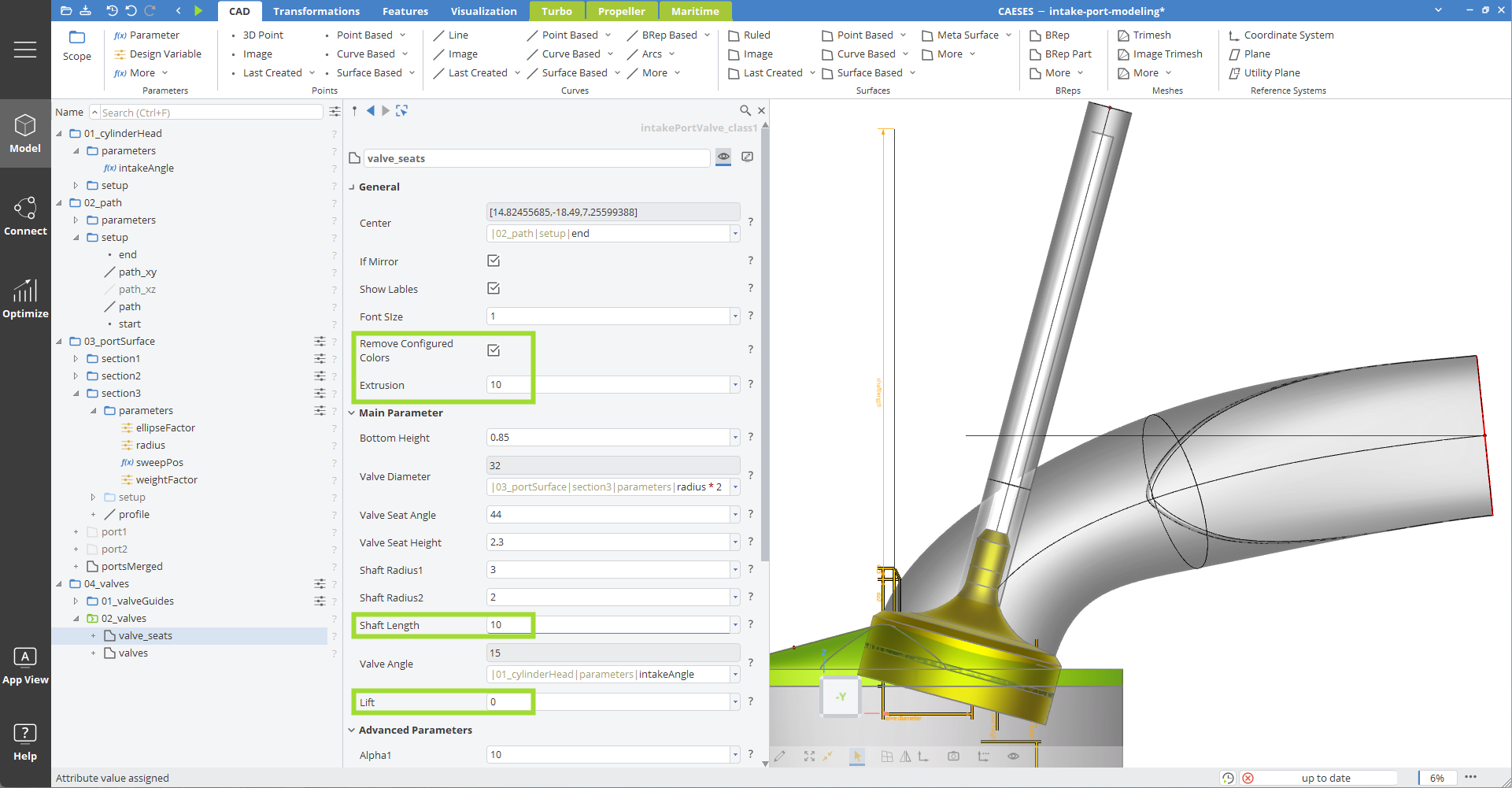
In order to create the valve seats on the cylinder head, we use the same feature.
- Select the feature instance valves.
- Duplicate this feature and set the name to "valve_seats".
- Set the arguments as:
- Remove Configured Colors:
true - Extrusion:
10 - Shaft Length:
10 - Lift:
0
- Remove Configured Colors:
Final Solid
In this last section we will combine all parts to a closed solid. We will take care to color the individual surfaces carefully, so that the CFD program can recognize the boundaries correctly.
- Create a new empty BRep via CAD > BReps > BRep and set the name to "finalSolid".
- For the first add sources operation do the following:
- Add the BRep portsMerged from the scope 03_portSurface
- For this operation create a new color with the name "portSurface".
- Add a new Closing | close planar holes operation.
- For this operation create a new color with the name "inlet".
Now we want to add the cylinder head and the valve seats to our final BRep solid.
- Add a new Boolean Operation.
- Add the cylinderHead BRep from the cylinder head folder to the sources. We already set the colors on the cylinderHead BRep, so we don't have to do it again in the final solid setup.
- Create a new Boolean | Boolean Operation.
- Add the BReps valveGuide1_negative and valveGuide2_negative to the sources.
- Set the operation method to Difference (this will subtract the valveGuide negative parts from the final solid).
- Set the color portSurface.
- Create a new Boolean | Boolean Operation.
- Add the BReps valveGuide1_positive and valveGuide2_positive to the sources.
- Set the operation method to Union.
- Set the color portSurface.
- Create a new Boolean | Boolean Operation.
- Add the BRep valve_seats to the sources.
- Set the operation method to Union.
- Set the color the portSurface
- Create a new Boolean | Boolean Operation.
- Add the BRep valves to the sources.
- Set the operation method to Difference.
Here is the finalized parametric intake port:
CAESES Project File
If you want to take a look at the finalized parametric model you can find the resulting CAESES project file intake-port.cdb here: