ANSYS ACT App
CAESES can be integrated into the user interface of the ANSYS Workbench. There is a comprehensive tutorial included in the Tutorials → Integrations which explains how the "CAESES Geometry Engine" App works within ANSYS. The essential steps are described again in this document.
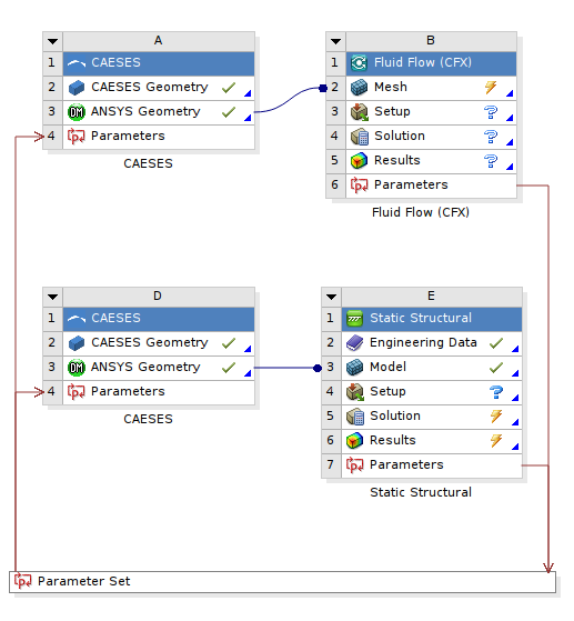
Load the CAESES Workbench App in ANSYS Workbench
In order to make CAESES available as an app in the user interface of the ANSYS Workbench, we need to install CAESES Workbench App within ANSYS Workbench platform. You can find the ACT extension in your CAESES installation folder etc > integration > ansys > CAESES_Workbench_App.wbex.
- Within the ANSYS Workbench, go to "ACT Start Page".
- In the opened "ACT Start Page", click on “Manage Extensions”.
- Within the Extension Manager, click on the "+" sign to install the CAESES Workbench App.
- Click on the little arrow at the lower right corner belonging to the CAESES Workbench App, and select “Load Extension” and “Load as default”.
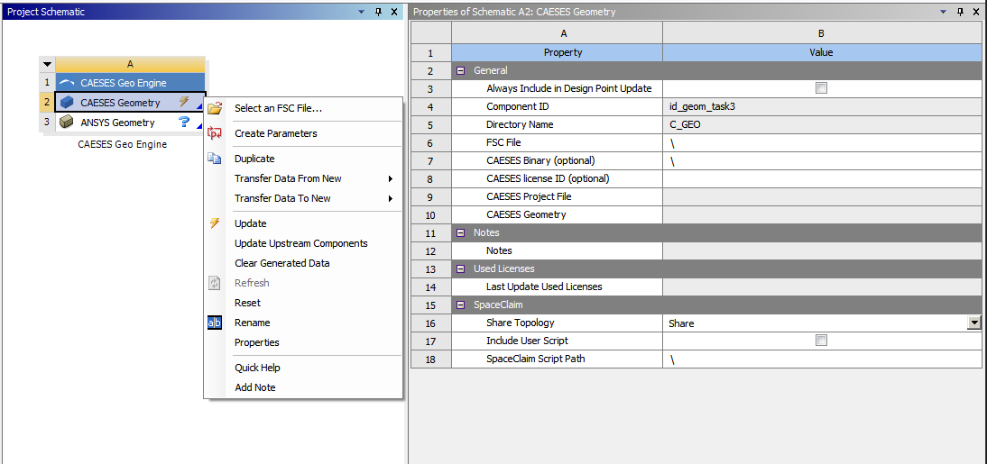
When you return to the Project Tab within the ANSYS Workbench, the CAESES App should be visible on the left-hand side within the section “CAESES Geometry”.
In case it does not appear, choose View > Toolbox Customization, and activate the system “CAESES” in the corresponding widget.
Preparing the CAESES Project
Typically, you would set up your CAESES model as usual in the user interface of CAESES.
Design Variables
In order to use the CAESES geometry model in the ANSYS Workbench, you need to have design variables with optional lower and upper bounds. These are the controls that get changed by the ANSYS Workbench, e.g. through optiSLang.
Export
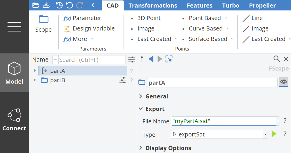
Secondly, you need to configure the exported geometry. This is done through scopes. Put all objects that should be exported into a single scope.
When you select the scope, you can set a file name and an export type. You can use any name such as "geometry.sat" but you need to use exportSat (ACIS export) as export type. This is required and will make sure your colors (patch name identifiers) are properly transferred as named selections.
Create a Script File
CAESES will be triggered in batch mode later on, which is done automatically by the ANSYS Workbench. We need a script file to control this batch mode run. Choose the following to generate the fsc script file to control CAESES in batch mode:
Menu > Project > CAESES Scripts > Export Script
You can store it somewhere on your PC. You can now also close your CAESES project.
See also the section Batch Mode of this help for more information about the batch mode run.
Load the CAESES Setup in the ANSYS Workbench
Now we can load the CAESES model within the ANSYS Workbench.
- Drag & drop a CAESES Geo Engine into the center widget of the ANSYS Workbench so that a new container gets created.
- In the context menu of the “Geometry” component, choose Select an FSC file…
- Select the fsc-file that you have exported previously. Alternatively, one can set the file location in the Geometry Property box by setting the “FSC file” input.
- Optional: In this box, the “CAESES Binary” is also an input, and needs not to be filled unless the user wants to use a specific CAESES version.
- Optional: In this box, the “CAESES license ID" is also an input, and needs not to be filled unless the user wants to use a specific CAESES license.
- Choose “Update” to run CAESES in the background, and to create geometry.
By using a double-click on the “Parameter Set”, you can directly change the design variables of the CAESES model. An update of the design point(s) triggers CAESES in the background again.
You can also further connect your components. For the meshing component, choose “Transfer Data to New” in order to connect it to other containers.
Named Selections
If you use colors in your CAESES setup, these colors are stored in the fsc-file. Based on this information, a connection to the named selections can be established.
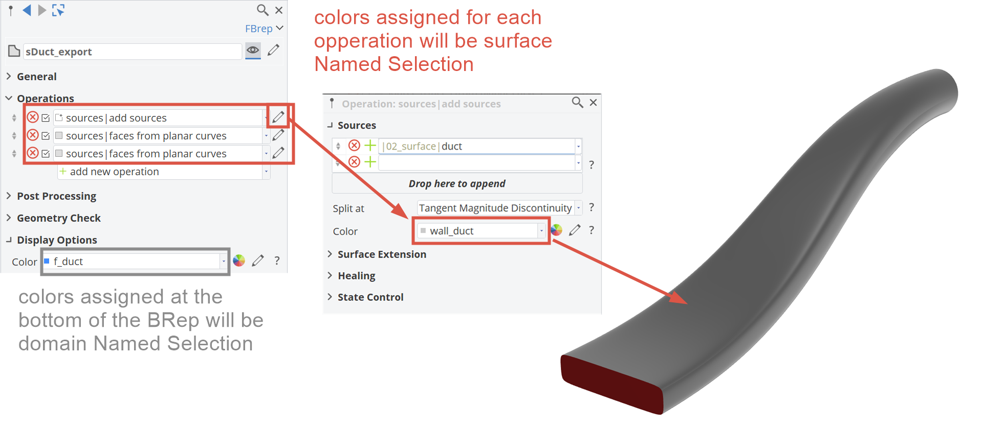
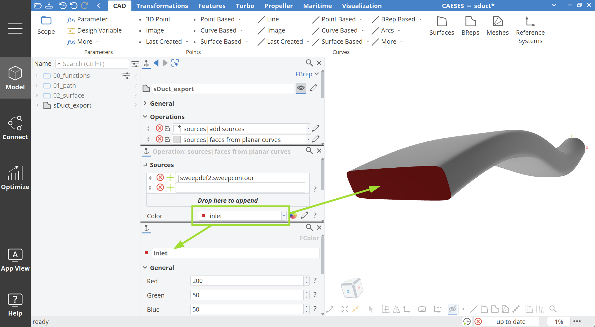
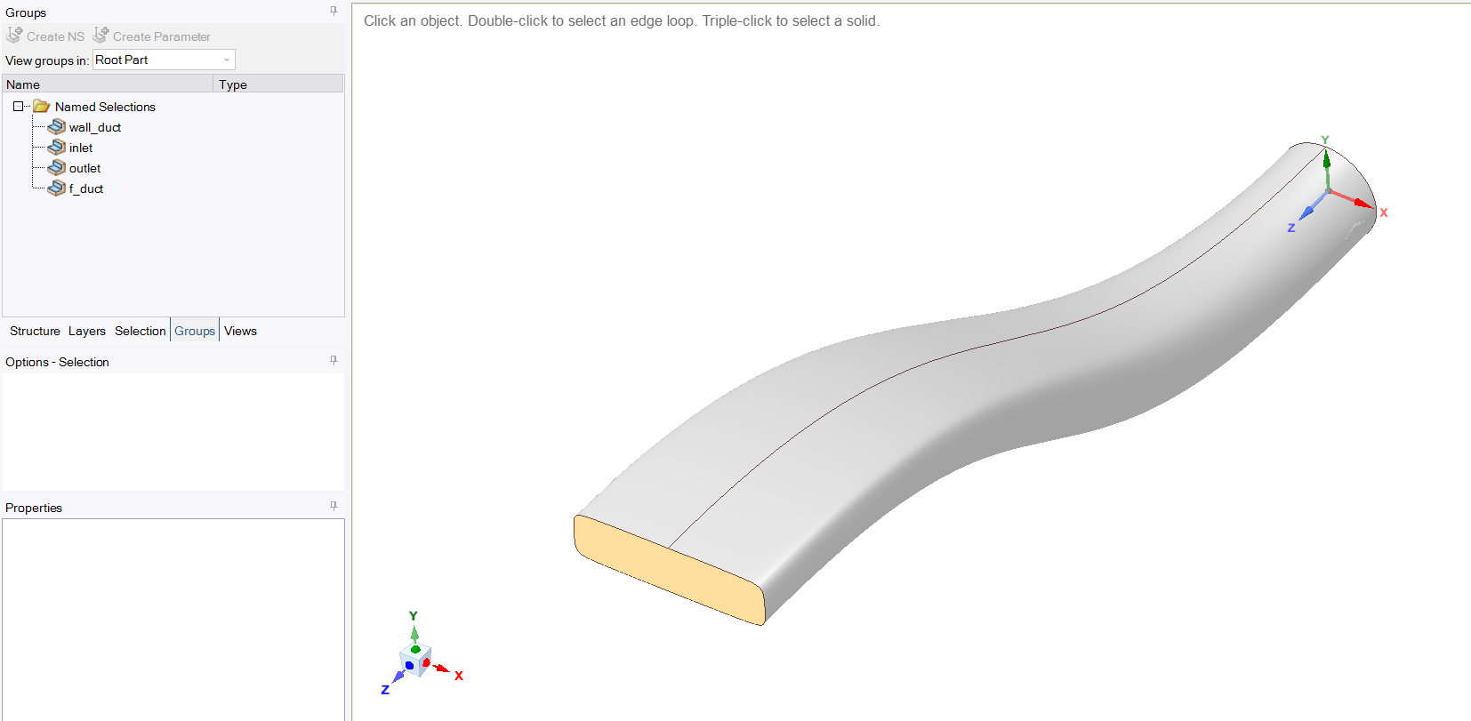
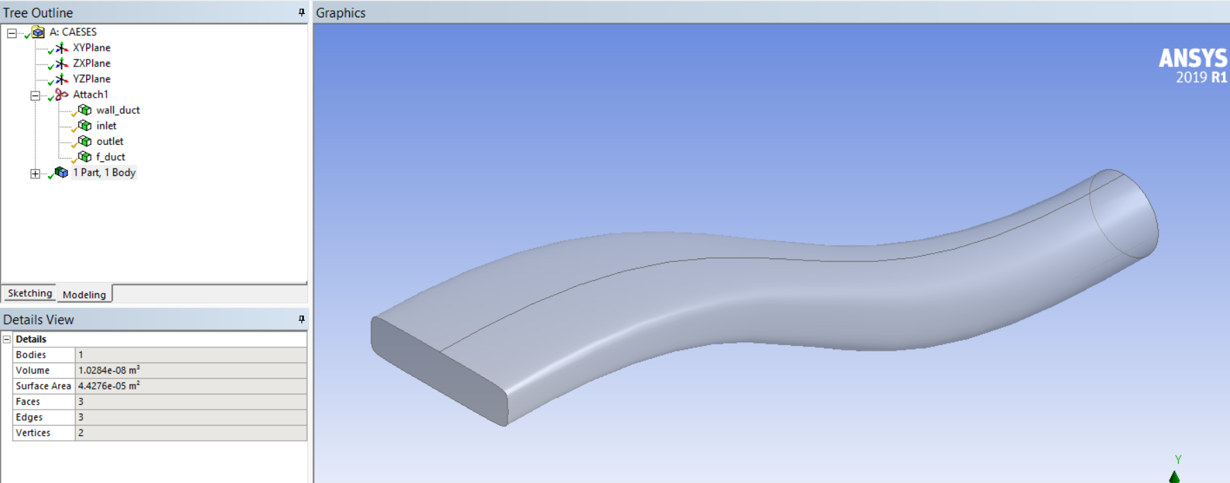
As a result, you will see your colored surface patches again as named selections in the ANSYS Workbench. This allows you to automate the meshing and analysis for all geometry variants that get created since these named selections are fixed.
SpaceClaim
If you use SpaceClaim instead of the DesignModeler, you need to go to the menu
- tools > options.
Select “SpaceClaim Direct Modeler” as the preferred geometry editor.
You also need to tell SpaceClaim to use the color tones from imported data, which you directly do in SpaceClaim through the menu
- file > SpaceClaim options > file options > general.
Simply deactivate the option "Use SpaceClaim color tones when importing" so that the imported colors are taken instead.
Discovery
If you use Discovery instead of the DesignModeler, you need to go to the menu
- tools > options.
Select “Discovery” as the preferred geometry editor.
You also need to tell Discovery to use the color tones from imported data, which you directly do in Discovery through the menu
- Settings > file options > general.
Simply deactivate the option "Use Discovery color tones when importing" so that the imported colors are taken instead.
CAESES TurboGrid Engine
There is also the CAESES TurboGrid Engine that allows you to transfer blade modeling data directly from CAESES to ANSYS Workbench. The app is similar to the geometry engine app, but transfers the blade data using TurboGrid files. Based on this app, the blade design can be fully automated with CAESES and the ANSYS meshing and simulation capabilities.
Please see the tutorial section where you find a step-by-step guide for the CAESES TurboGrid Engine.