Parametric Geometry Modeling in CAESES
CAESES contains comprehensive CAD capabilities to set up efficient parametric geometry models that are ready for manual and automated variant creation. The following sections introduce some basic concepts that are at least good to know if you do your first steps in CAESES.
How it Works
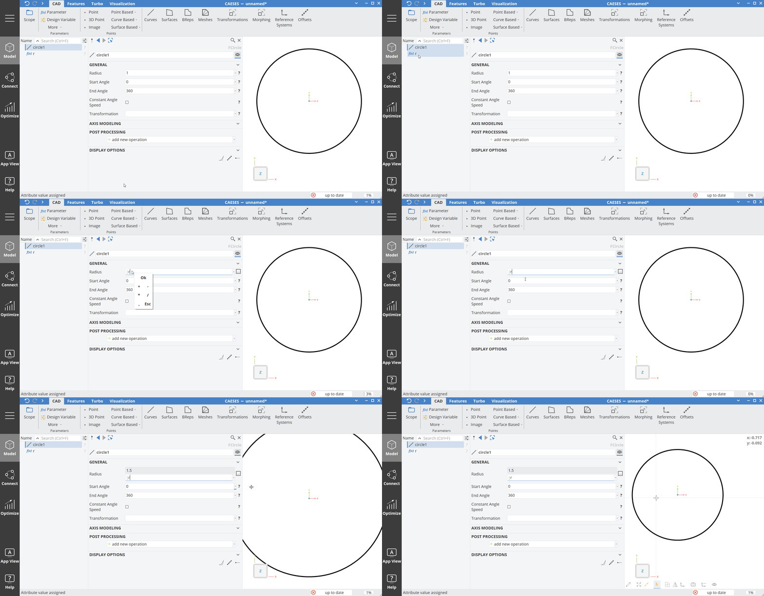
Basically, you create objects through the CAD menu of CAESES, and then you go through the properties of such an object and enter the required properties step by step. There is no sketch plane that you need to select first and nothing to learn in terms of interactive modeling or shortcuts etc. Just create objects from the menu and set their properties through the object editor.
Create objects through the menu, and set their properties in the next step. A simple concept!
Dependency-Based Modeling
There is a large set of e.g. point, curve and surface types that can be connected to each other so that a clean object-oriented dependency structure gets created, to create fully-parametric geometry models. As a result of this dependency-based approach - as opposed to the history-based approach of conventional CAD systems - CAESES models can be robustly varied during automated optimizations. CAESES models typically do not break or fail to regenerate.
Types and Commands
CAESES is an object-oriented and command-driven environment, wrapped into a graphical user interface.
CAESES is an object-oriented, command-driven environment!
Each geometry object in CAESES has a special type that provides special functionality including a specific command set. The most important commands are setter and getter commands for the object properties, but also object commands to do calculations based on the object data.
Set Commands
Set and get commands are often triggered in the background when you do interactive modeling. However, you can also directly access and use the objects and their commands, e.g in feature definitions or editors. For instance, if you set the radius of a circle in the graphical user interface of CAESES, the command .setRadius() is called internally, without really indicating it to the user.
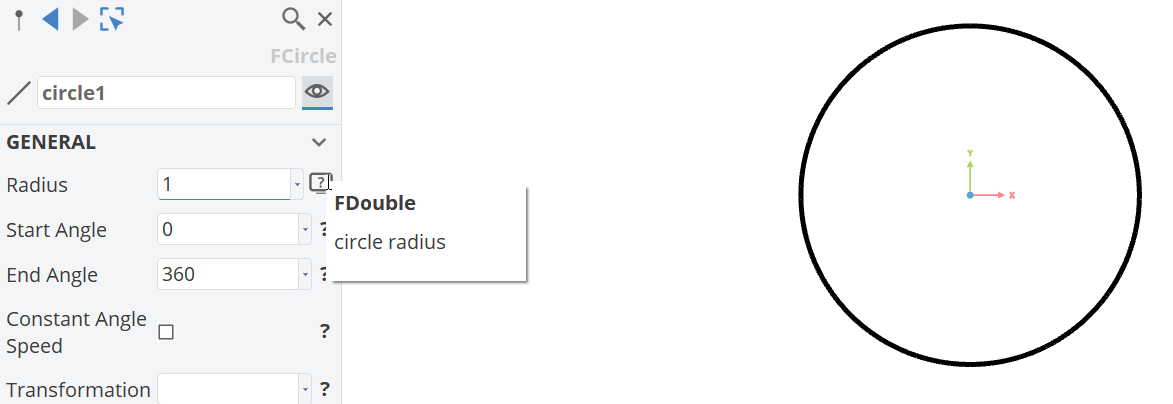
Command Structure
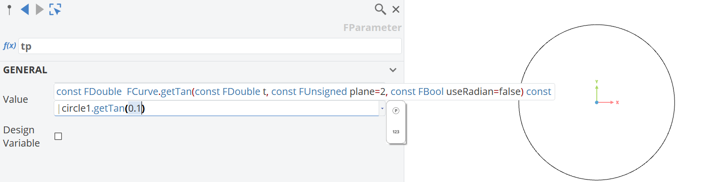
Commands in CAESES typically have a name, input arguments and an output type. When you can use Ctrl+Space inside the brackets to use auto completion and to see the necessary input arguments.
Default Arguments
If an input argument has a default value (e.g. FDouble t0 = 0), you don't have to specify it explicitly when using the command if the default value is fine.
Command Documentation
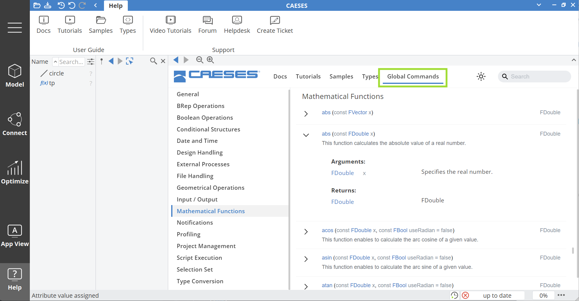
You find the full command documentation in the documentation browser:
Hierarchy
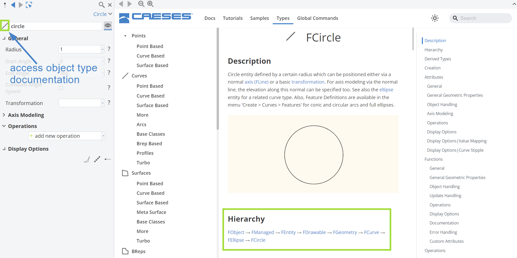
The different object types belong to a CAESES hierarchy, similar to class hierarchies in programming languages such as C++ and Java. Consider the following hierarchy example:
FCurve>FEllipse>FCircle.
If you create a circle in CAESES, it has the type FCircle. This type provides circle-specific functionality (commands), e.g. to set and to get the radius of the circle.
The primary parent type of FCircle is "FCurve". This type provides general curve functionality that can be used also by any other curve type such as splines, lines, and also the circle.
Example functionality from the FCurve type are curve position commands such as .getPos(), as well as tangent and normal calculations.
You can click on the type icon of a selected object to see the full type documentation, including commands that you can potentially use and trigger on the object (using the convention objectname.commandname(arguments)):
Creating Dependencies
In order to parameterize your geometry model and to connect objects to each other, simply drag and drop an object into an appropriate editor of another object. You can also type the full names (including all scopes) into editors.
Type Input and Output
Create a line and try to drag & drop a 3D point into the start position editor of the line.
When connecting objects, it is important to know that the target input type needs to fit the source output type. For instance, a line object expects two vectors (FVector3) as input types. These two vectors can come from two 3D points but can also be a simple vector expression that you type in, such as [0,0,0].
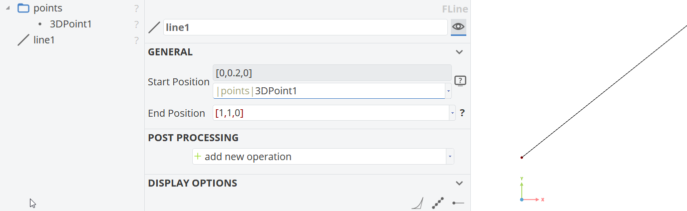
The line start position expects the base type FVector3 type. Click on the help icon (❔) of this editor on the right-hand side. The 3D point implicitly returns a FVector3. The expression [0,0,0] is also interpreted as FVector3.
Expressions
Instead of only connecting geometry objects to each other, you can also enter expressions into editors. For the line example from above, you could e.g. use a position command from another curve which returns a vector again.
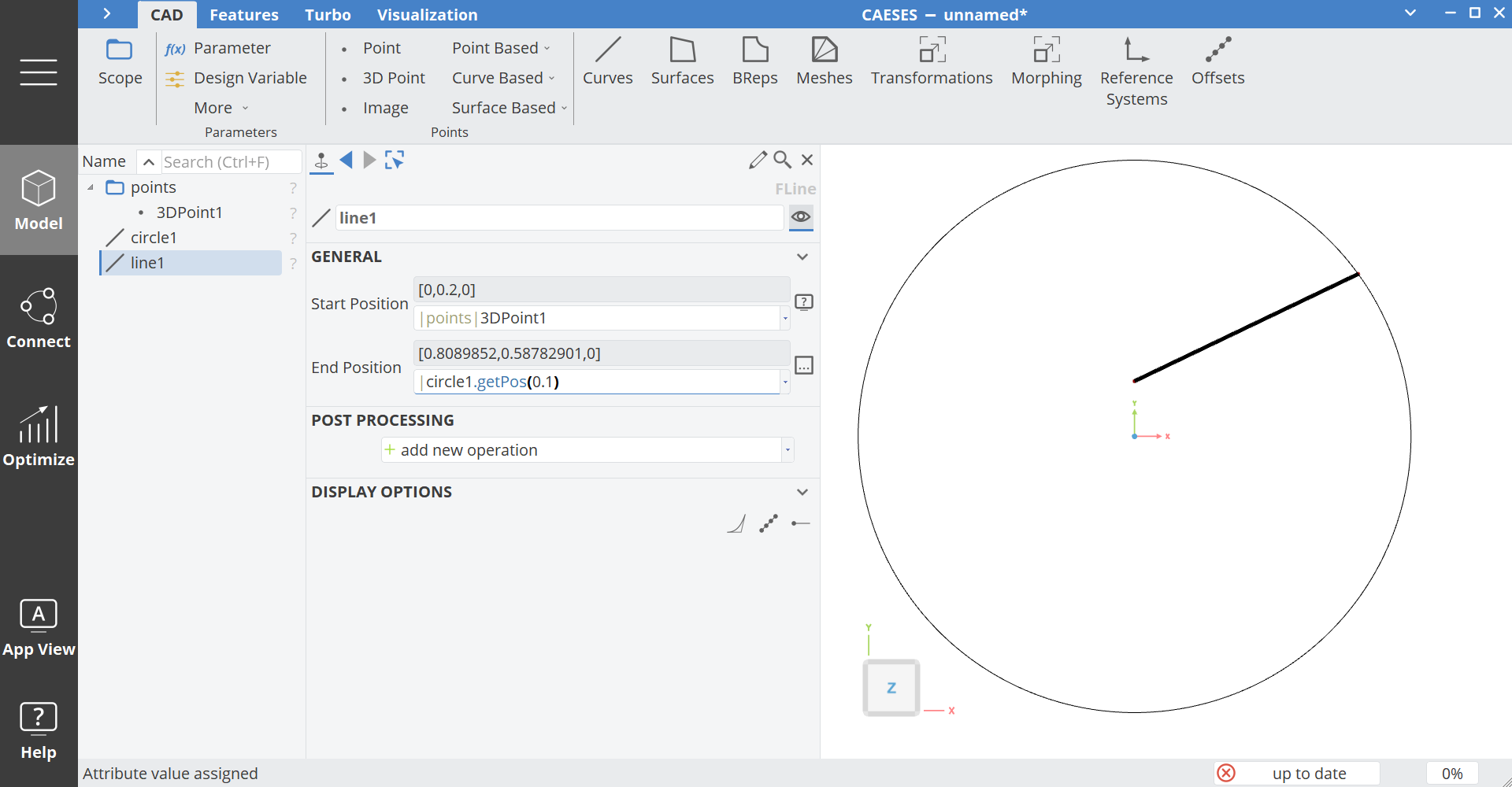
Besides the type-specific commands that you trigger on objects (e.g. circle.getPos() or circle.getRadius()), you can also use global commands such as mathematical functions to create expressions. You find these commands in the documentation browser.
An example for using a global command is shown below where a sqrt() command is used within an expression to define the y-coordinate of a point:
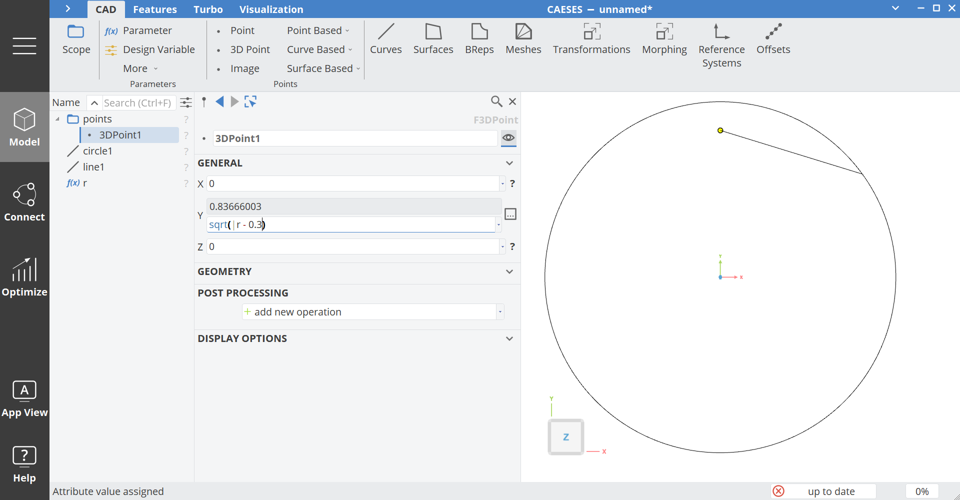
The parameter r in this example can also hold any complex expression, and not just values. See the section Parameters for more information.
From Parameters to BReps
In modeling — and especially in parametric modeling — creating a proper CFD-ready solid geometry often requires a BRep (Boundary Representation).
A BRep is a collection of connected NURBS surface patches that together form a closed solid.
To achieve a valid BRep:
- You need smooth and continuous surfaces.
- To build smooth surfaces, you need well-defined curves (typically NURBS curves).
- To construct curves, you need properly defined (control) points.
- Point properties are defined by parameters, which form the foundation of parametric models.
Thus, the modeling hierarchy can be summarized as:
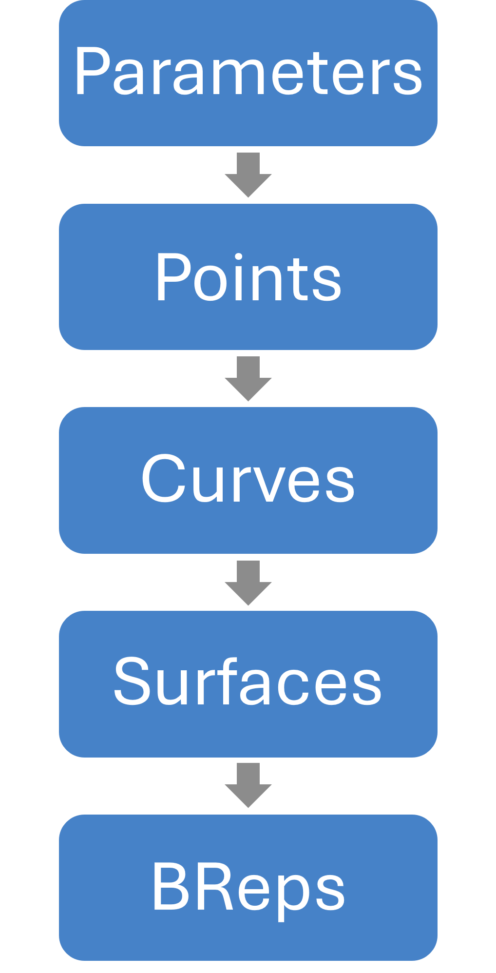
It is not always necessary to explicitly follow every step of this chain, but it illustrates the hierarchy from parameters to closed BReps, showing how complex geometry is constructed step by step. It also highlights the connections between each geometric entity in the diagram.