Basic Characteristics
Marine propellers are crucial components in ship propulsion systems, converting rotational power into thrust to propel vessels efficiently through water. The design and selection of a propeller significantly influences a vessel's performance, fuel efficiency and overall functionality.
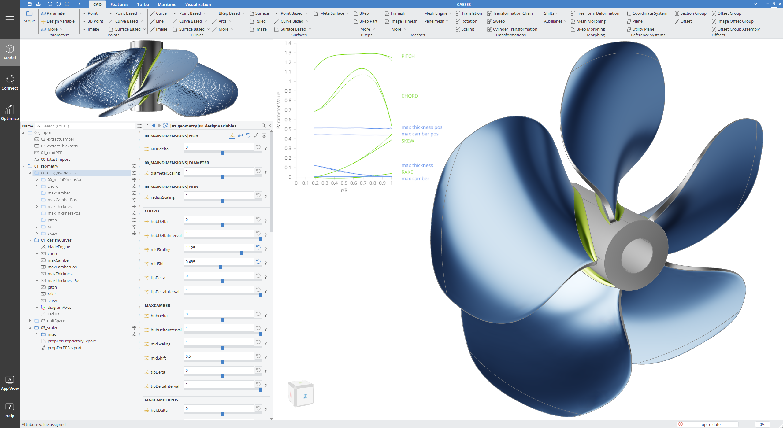
Designing marine propellers requires balancing various factors to achieve the best possible performance, structural integrity, fuel efficiency and operational capability. While this documentation does not capture every aspect of marine propeller design, it offers a solid foundation for understanding the fundamentals and the complexities involved. In CAESES, we have developed specialized propeller design features to simplify this intricate task, making it more accessible and enjoyable for users. By utilizing these tools and the information provided, designers can effectively refine their propeller designs, helping to advance marine propulsion technology and enhance the efficiency and performance of vessels.
This documentation supports you in understanding the design process and best practices for creating a propeller using CAESES. It provides a comprehensive guide to various aspects of marine propeller design, including
- basics of propeller design,
- the surrounding environment,
- its profile definition,
- the geometry of the propeller including the radial distributions,
- various types of propellers like,
- structural design considerations, and
- CFD Methods.
Parts of the Propeller
-
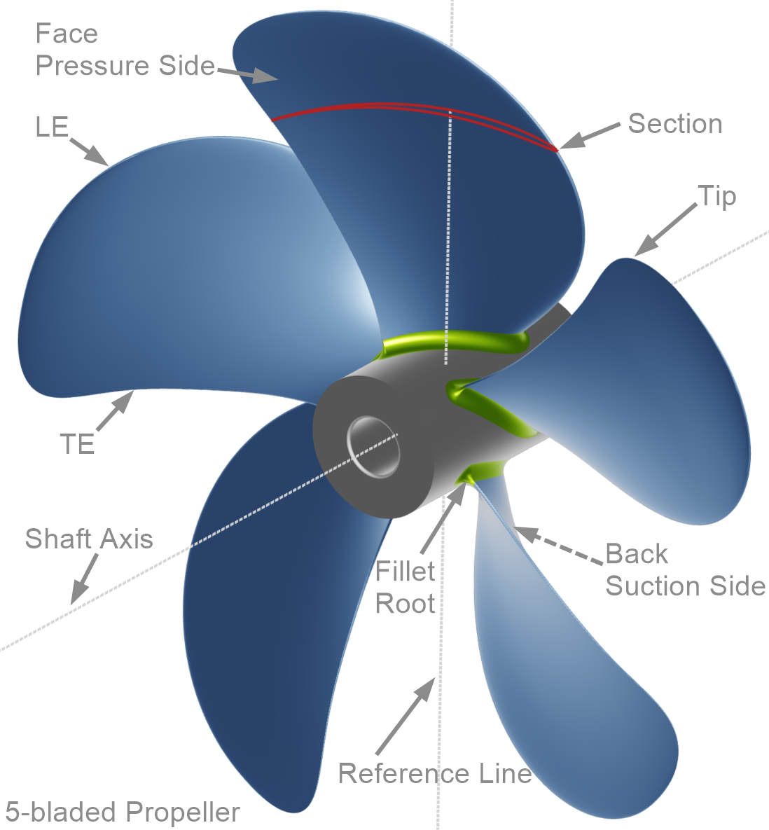
Hub: The hub or boss of a propeller is the solid central disc. It includes a drilled borehole for the propeller shaft. The propeller blades are attached to the hub. Since the hub generates no thrust, the ideal would be to eliminate it. However, as a practical matter, the hub can rarely be less than 14% of the diameter in order to have sufficient strength [2].
-
Blades: The propeller blades are the twisted fins or foils that project out from the hub. It is the action of the blades that drives a boat through the water.
-
Face & Back: The blade has two conceptual sides. The face (or pressure side) is the high-pressure side of the blade, facing aft and pushing water when the boat is moving forward. Conversely, the back (or suction side) is the low-pressure side of the blade, facing forward. Typically, for regular foils, the resulting force distribution is approximately 2/3 from the suction side and 1/3 from the pressure side [3].
-
Root & Fillet Area: The blade root is where the blade attaches to the hub, while the fillet area is the transitional region where each blade meets the hub, facilitating fluid flow around the attachment point.
-
Tip: The extreme outermost edge of the blade, as far from the propeller shaft center as possible.
-
Edges: The leading edge (LE) of a blade is the edge that cleaves the water. The trailing edge (TE) is the edge from which the water streams away.
-
Blade Section: The cross sectional shape curve at any radius is the profile blade section formed by the intersection between the propeller blade and a coaxial cylinder, defining the blade's cross-sectional geometry.
Diameter
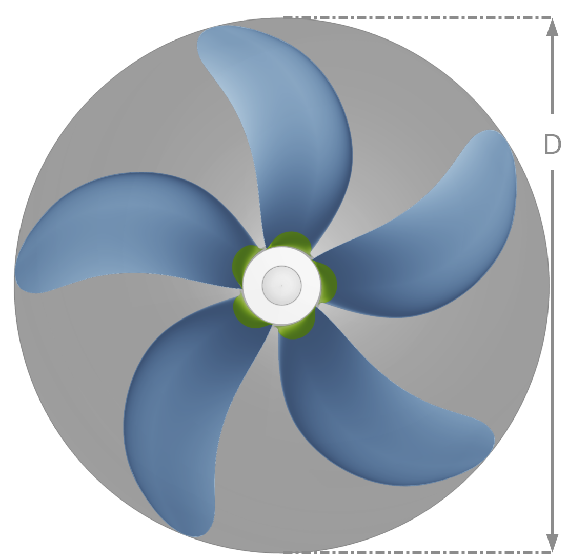
The diameter (D) of a propeller is the distance across the circle swept by the extreme tips of its blades (see figure below). Diameter is the most crucial factor determining how much power a propeller can absorb and transmit, directly influencing thrust delivery. Additionally, it serves as a scaling factor in the propeller's model.
In general, larger diameters enhance propeller efficiency across various marine applications. Even a small increase in diameter significantly increases both thrust and torque loads on the engine and shaft. Larger diameters require slower shaft RPMs for optimal efficiency. Factors such as draft limitations, hull design, RPM constraints and reduction gear losses typically restrict propeller diameters to levels well below theoretical maximums. However, high-speed vessels (exceeding about 35 knots) may experience excessive drag from larger-diameter shafts and bearings. This means that while larger diameters are generally beneficial, their advantages diminish in certain high-speed applications where minimizing drag becomes a priority.
Propeller Disc Area:
The disc area of a propeller is the area (grey area in the figure above) of the circle described by the maximum propeller diameter (D) and can be calculated by the following equation:
Number of Blades
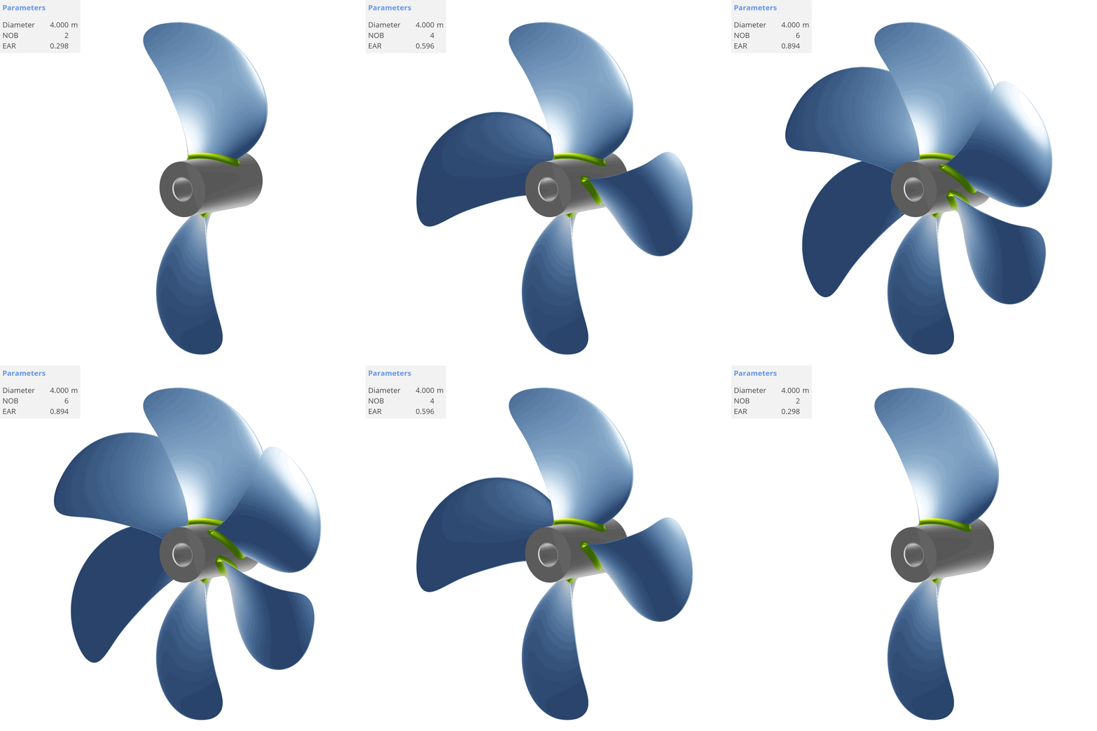
The number of blades (Z or NOB) on a marine propeller typically ranges from 2 to 7, influencing various aspects of vessel performance and are placed symmetrically around the hub as shown in the animation below. The animation also shows the Expanded Area Ratio (EAR) and how it changes by changing the number of blades.
- Two-bladed Propellers: Common on sailboats and high-speed powerboats to reduce drag. They require larger diameters to achieve effective thrust, which may not be practical for all vessel types. Two-blade propellers are also preferred when low loading conditions are present, as they provide sufficient thrust with minimal drag.
- Three-bladed Propellers: Strike an optimal balance between blade area and efficiency, making them widely used across various vessel types. They are particularly favored for general performance and small, high-speed boats. Three blades offer better structural integrity compared to two-blade propellers and are suitable for handling higher loads.
- Four to Six-Bladed Propellers: Offer increased total blade area without requiring larger diameters, making them beneficial in space-constrained situations. They have the potential to reduce vibration by distributing forces more evenly but tend to be less efficient than three-blade propellers due to increased turbulence from closer blade spacing. They are mainly used for large commercial vessels.
- Seven-Bladed Propellers: Typically used for submarines because they minimize noise and vibration, which is crucial for their stealth operations. Seven blades are designed to operate quietly and efficiently under conditions where noise reduction is a top priority.
Choosing the right number of blades depends on factors such as vessel size, speed requirements and space constraints. It involves a trade-off between achieving the most efficient propeller performance and addressing other factors, such as reducing noise and cavitation.
Revolutions per Minute (RPM)
Revolutions per minute (RPM or n) refers to the number of full turns or rotations a propeller makes in a single minute.
- Engine RPM: Can differ significantly from propeller RPM, which is the speed of the engine's crankshaft.
- Reduction Gears: Typically installed between the engine crankshaft and the propeller shaft to reduce RPMs and increase torque. This allows for the use of larger, more efficient propellers while maintaining compact, high-speed engines.
- Lower RPMs: Larger-diameter propellers are more efficient for vessels operating below 35 knots. These propellers can move more water with each rotation, providing greater thrust while spinning slower. This setup enhances fuel economy and ensures smooth, efficient propulsion by reducing the need for high tip-speeds, which helps in minimizing drag and torque requirements.
- Higher RPMs: For high-speed vessels where minimizing appendage drag is crucial, smaller propellers with higher RPMs, along with smaller shafts and struts, can be beneficial. Smaller propellers spinning faster can help reduce drag and resistance, allowing the vessels to achieve higher speeds more efficiently. This approach minimizes the torque required by reducing the propeller diameter, which in turn lowers the drag caused by high tip-speeds.
Advance Ratio (J)
A dimensionless parameter in propeller theory that describes the ratio of the free-stream velocity () and the tip speed of the propeller. For a propeller with constant geometry, where the blade shape and size are fixed and the blade angle does not change, the angle of attack remains constant across all blades at a given advance ratio, regardless of the speed of advance (). The advance ratio is defined as follows:
- Low Advance Ratios (): The propeller operates in high-thrust, low-speed conditions.
- Intermediate Advance Ratios (): A balance between thrust and efficiency is maintained.
- High Advance Ratios (): The propeller prioritizes efficiency at high speeds.
Reynolds Number (Re)
A dimensionless parameter in fluid dynamics that characterizes the flow conditions around a propeller, indicating whether the flow is laminar or turbulent. The Reynolds number at a specific radial position (, where is the chord length at radius ) is crucial for propeller design. This means e.g. is the chord length at 70% of the propeller radius. For practical purposes, the radius at is often examined as it provides a representative measure of performance. The Reynolds number is defined as, where is the kinematic viscosity of the fluid:
- Low Reynolds Numbers (): Flow is typically laminar.
- Intermediate Reynolds Numbers ( to ): Flow can be a mix of laminar and turbulent.
- High Reynolds Numbers (): Flow is mainly turbulent.
A favorable Reynolds number depends on the specific application and desired performance characteristics. For most marine propeller applications, Reynolds numbers in the intermediate range ( to ) are common. This range helps balance between avoiding excessive drag due to turbulent flow and ensuring sufficient flow mixing to prevent separation. In real-world applications, laminar flow is rarely encountered and is more commonly observed in model basin tests.
Thrust & Torque
- Thrust (): Refers to the force that propels a vessel forward through the water. It is generated by the interaction of the propeller blades with the water, pushing the vessel in the direction opposite to the water flow expelled by the propeller. The generated thrust must be greater than the ship's resistance to accelerate the vessel [4].
- Torque (): Represents the rotational energy delivered by the engine to the propeller. It measures the engine's ability to generate rotational force, which is then converted into thrust and other (undesired loss) effects such as vortices and viscous drag. Torque, along with RPM, are usually the limiting factors for the engine's performance. It also affects how efficiently the engine's power is utilized, where power () is given by the equation ( ).
Open Water Characteristics
Open Water Characteristics refer to the performance characteristics of a propeller when it operates in an ideal, unbounded water environment with density ( ). These characteristics are derived from the non-dimensional parameters thrust coefficient ( ) and torque coefficient ( ). From these coefficients, one can determine the propeller open water efficiency ( ).
Open Water Diagram
The open water diagram graphically represents the relationship between the thrust coefficient ( ), the torque coefficient ( ) and the efficiency ( ) for a propeller at various advance ratios ( ). This diagram helps visualize how the propeller performs under different operating conditions and allows for the comparison of propellers based on their dimensionless coefficients, providing insights into their efficiency and operational characteristics.
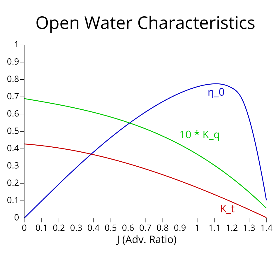
In general, operating on the left side of the peak of the propeller efficiency curve is preferred. The curve on the right side of the peak is steeper, meaning efficiency drops off more rapidly. By maintaining a range of operating conditions on the left side, the propeller can achieve higher efficiency values over a broader range of speeds.