Turbomachine Types
The key function of turbomachines is to introduce energy into a continuous fluid flow or extract energy from it. This conversion of energy is accomplished by a continuously rotating component, called rotor, which either turns mechanical energy from the shaft into pressure energy (to e.g. enhance efficiency in the thermodynamic cycle), or harvest energy from the fluid to transform it into mechanical energy. Turbomachines that increase the fluid's energy are classified as power delivering machines, also widely known as compressors if the increase of pressure is high or fan for low pressure increase, while machines that extract energy from the fluid are known as power receiving machines or turbines.
Another distinction between turbomachines is the direction of flow. Machines in which the flow enters and exits primarily in the same direction are specified as axial turbomachines, whereas radial turbomachines redirect the flow from an axial inflow towards a purely radial outflow. Diagonal Turbomachines can be viewed as somewhat in between of the first two classifications, where the fluid does not exit entirely radially.
Turbomachines are also differentiated by the characterization of the fluid. Here, thermal turbomachines comprise machines which handle compressible fluids. In contrast, machines in which incompressible fluids traverses are defined as hydraulic turbomachines. The graphic below visualizes the different classifications together with specific examples that are used in the industry. [4]
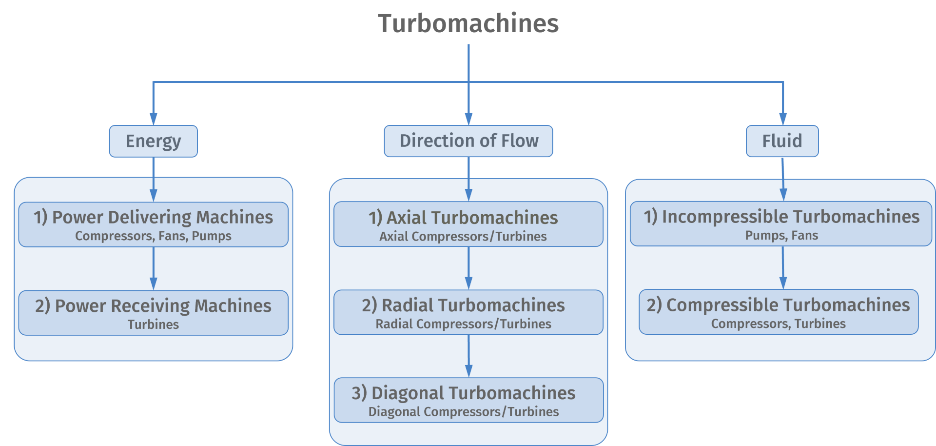
Which Design to Choose?
At the beginning of every turbomachine design, the engineer needs to find a good baseline design, which defines the overall structure of the machine. After the machines boundary conditions (speed , volumetric flow rate , pressure ratio and specific flow work , type of fluid and energy transfer) are determined, which in most cases are immutable constraints, two dimensionless design parameters, the specific speed and specific diameter are evaluated. With these design parameters, engineers can utilize the empirically derived Codier-Diagram, which helps to estimate the overall machines design. The graph below shows such an empirically derived graph for power delivering- as well as power receiving machines. Since this is a simplified version mostly used for educational purposes, it recommended to use more detailed diagrams.[1], [5]
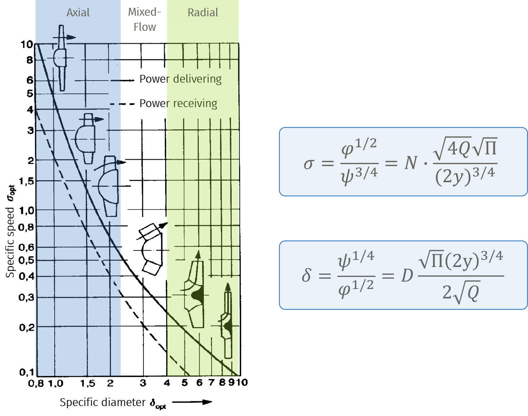 Codier Diagram [1]
Another design parameter is the non-dimensional rotational speed , which is often called "specific speed" in English literature. This parameter is defined slightly different from the previously introduced specific speed . It sets the speed of a geometrical similar turbomachine in relation towards the volumetric flow at a certain effort of specific flow energy. Because of this parameter, axial machines are often known as fast rotating machines () due to the large volumetric flow these machines process even though their rotational speed is relatively slow compared to radial turbomachines, which are usually processing less volumetric flow and hence are labelled as slow rotating machines (). In contrast to the lower volumetric flow are radial machines able to achieve higher work coefficients per stage than axial machines due to the centrifugal force, which stabilizes the fluid flow. [2], [5]
 Non-dimensional rotational speed
Because of these characteristics, axial machines are used in fields that process large volumetric flows and where size is not a crucial limiting factor, i.e. in aircraft engines or gas turbines. Radial machines are often applied in cases where a high energy transfer per stage is required, which makes these machines more compact than axial machines. These machines can be found e.g. in piston engines as turbo-chargers or in stationary machines which require a compact design, e.g. in chemistry- or electric power plants. [5]
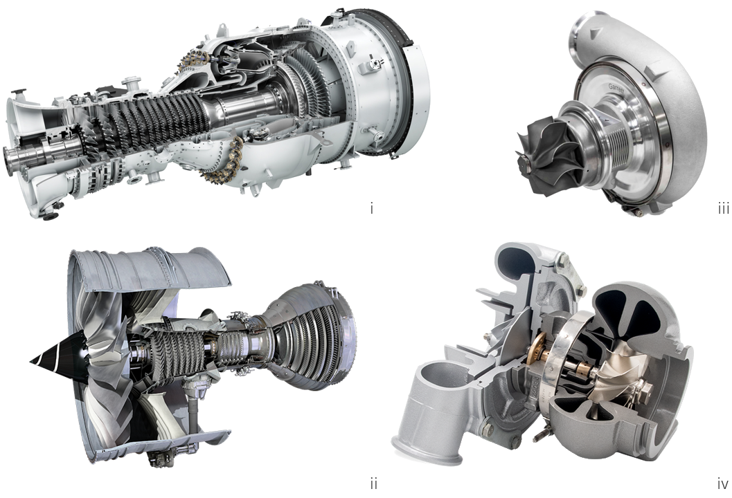 i: Axial gas turbine Siemens SGT-800 [A], ii: aircraft engine Rolls-Royce Trent-1000 [B], iii: Garrett turbocharger G-Series G57-2550 98MM [C], iv: Turbo Charger [D]