Morphing
Shape deformation and morphing techniques allow you to quickly change and optimize existing NURBS geometries, sectional point data, or even discretized surface meshes and volume meshes (e.g. ANSYS Fluent meshes, VTK data, STL). We have the following methods available:
RBF Morphing
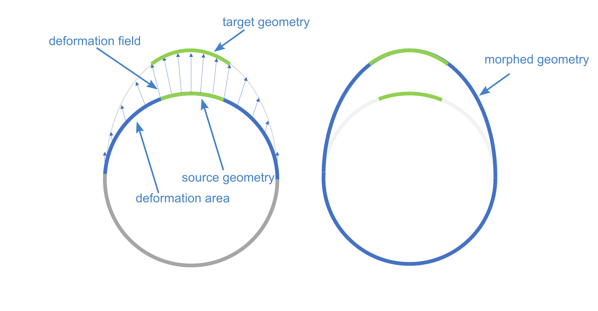
RBF Morphing techniques are a very powerful and easy to use methods to deform imported geometry. Internally the geometry will be morphed according to a deformation field. And within a defined tolerance the geometry is modified in a way to match the deformation field, like shown here very simplified:
Mesh Morphing
With this technique imported tessellated data like STL files can be morphed interactively. But you can also convert BReps into tessellated geometry. The deformation field can be created with the Morphing Method:
- Vector Handle
- Generic Transformation
- Source / Target Curves
The example below shows a quick demonstration of a Mesh Morphing with a Vector Handle method.
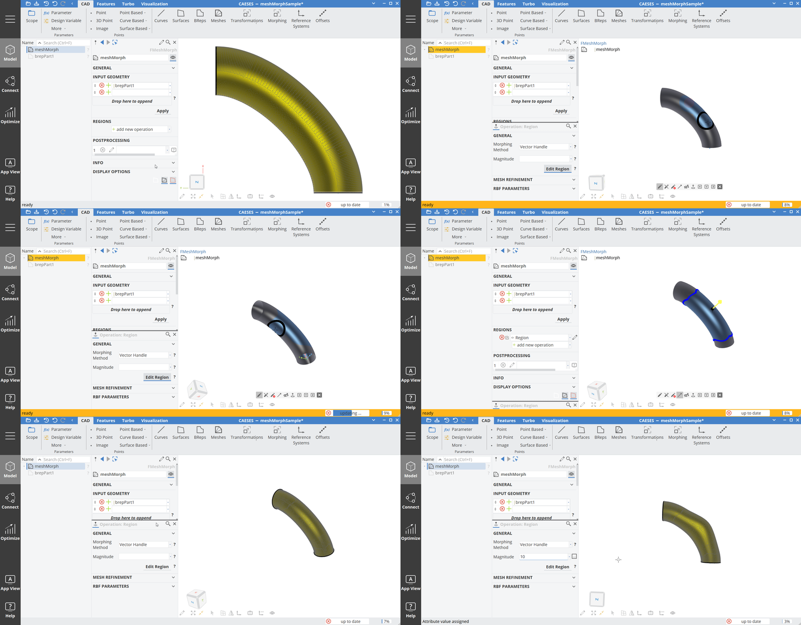
You can also use different regions in a chain, which are stacked on top of each other.
Follow the step-by-step tutorial on Mesh Morphing for more details.
BRep Morphing
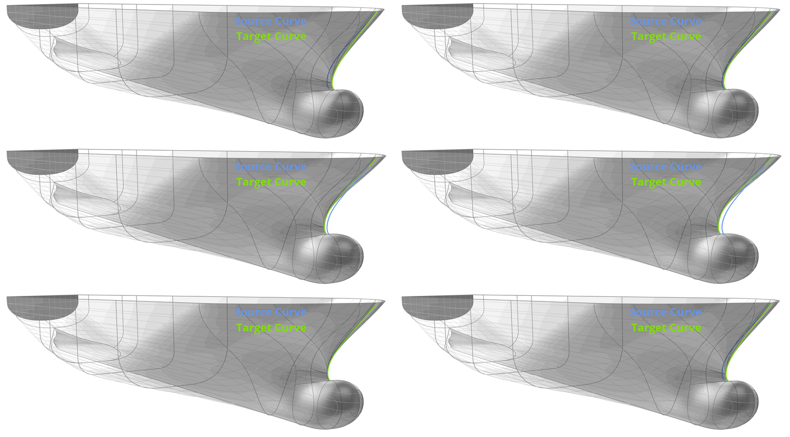
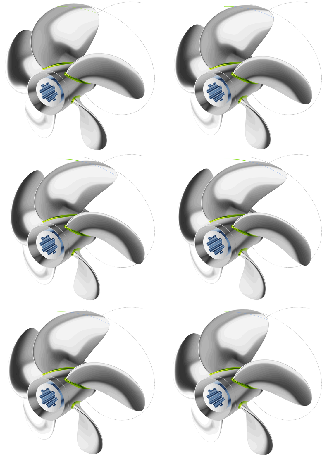
With this method, we can deform BReps and NURBS based files (STEP, IGES, SAT...). To define the deformation field for this method, we can define source and target geometries. These can be Points, Curves and Surfaces.
Follow the step-by-step tutorial on BRep Morphing for more details.

Free-Form Deformation
This type of transformation allows you to deform geometry within a specified box. This box is basically a B-Spline-volume with vertices where you control these vertices. The movement of the vertices define how the geometry within the box will be deformed. Presets allow you to expand or rotate vertices, for instance. One has to select which vertices to use, as well as the continuities, to have smooth transitions from deformed to untouched geometry parts. The free-form deformation can be found in the menu
- Model > Transformations > Morphing > Free-Form Deformation
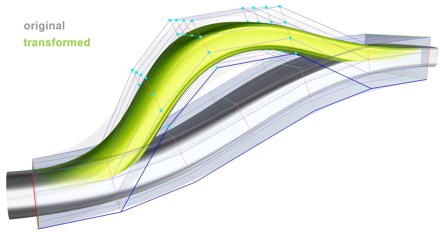
Here is an example how to setup a Free-Form Deformation with an sweep box which is swept along a path.
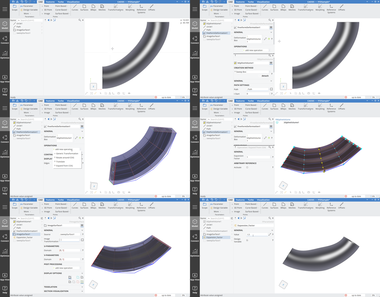
Follow the step-by-step tutorial on Free-Form Deformation for more details.
Shift Transformations
CAESES offers so-called shift transformations to deform or shift geometries with regards to the principal axes x, y and z. You can find these shifts in the menu
- Model > Transformations > Shifts.
The following shifts are available:
Delta Shift
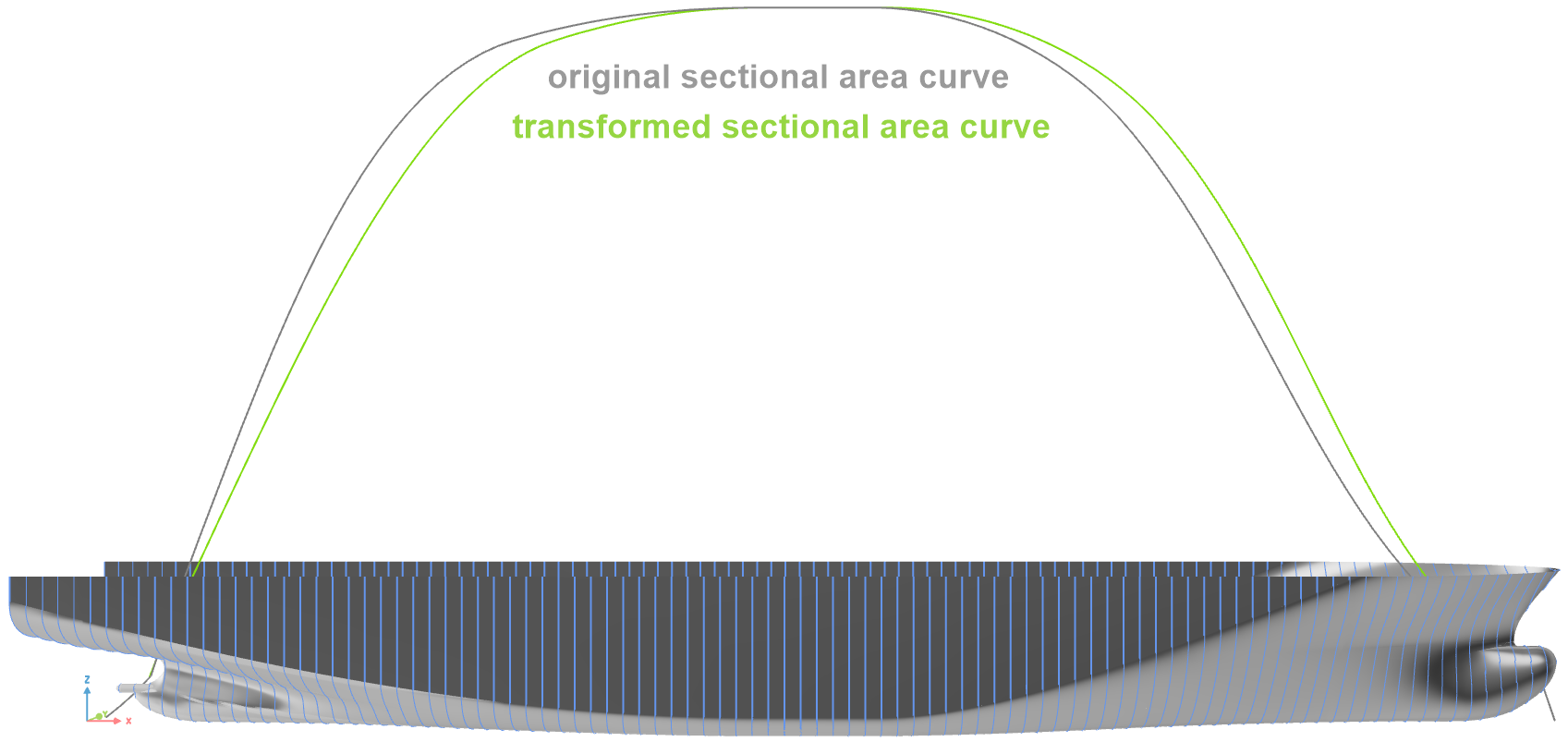
This is a shift method which is typically used in ship hull design. It allows you to specify a 2D function graph to shift a surface or 2D sections (point data) in x-, y- or z-direction. You can additionally combine several functions also for other directions by using the delta sum and delta product objects that you find in the menu CAD > transformations > auxiliaries. Typically, ship hull sections are transformed in x-direction where the delta function provides the delta values for each x-location.
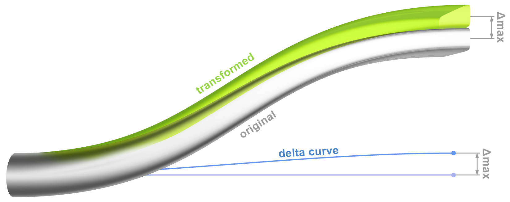
Surface Delta Shift
Similar to the curve-based delta shift from above, this one works with a 3D delta surface that gets projected and added to the original geometry. The delta surface provides the delta information that is taken to deform the geometry in x-, y- or z-direction.
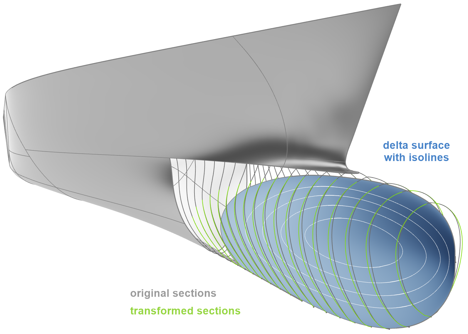
Lackenby
This is a shift transformation that is used in ship hull design, to quickly deform and optimize existing ship hulls. You can control the center of buoyancy as well as the displacement changes. This transformation is part of the CAESES maritime add-on, and a hydrostatic calculation is needed to use this object. Both the lackenby and the hydrostatic setups are explained in a tutorial that is shipped with CAESES.
Cartesian Shift
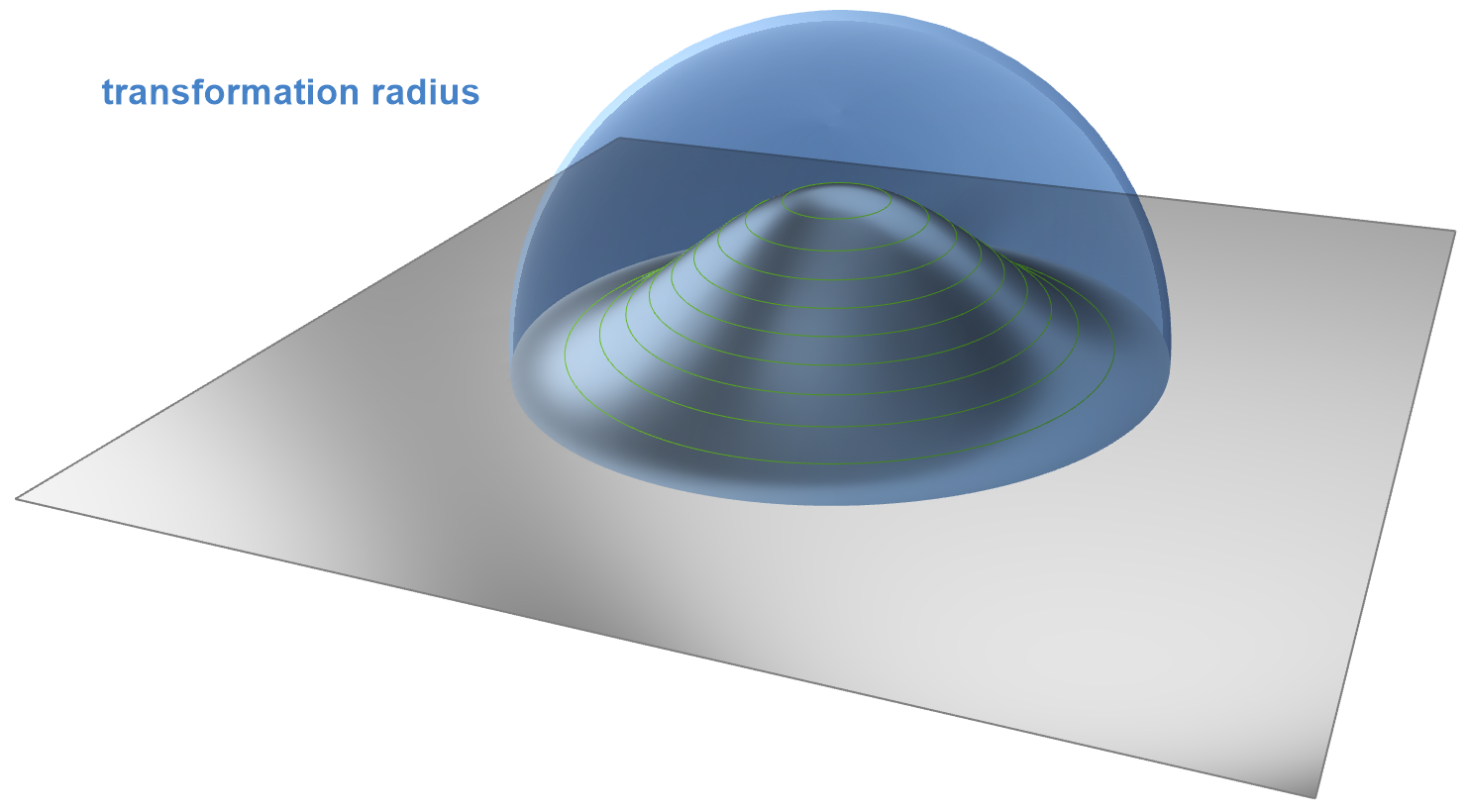
With the cartesian shift you specify a center source position of an ellipsoid where the geometry within this ellipsoid will be deformed in a smooth manner. You can specify the amplitude as well as the dimensions of the ellipsoid.
How to Use Deformations
The basic concept to transform existing geometry with FFD or Shifts, follows a simple procedure:
- Create an image of the geometry
- Create and configure the transformation (delta shift, free-form deformation, etc.)
- Set the transformation at the image.
You have to create images from your original geometry in a first step. You can find images in the corresponding CAD menus. For instance, in order to deform a set of surfaces, you can choose CAD > surfaces > image surface group, while STL data would be put into an image trimesh that you find in the menu CAD > meshes and solids > image trimesh.
Then you have to create and configure your transformation that you want to apply to the image. For most of the transformation types in CAESES, you can find tutorials in the tutorial section of the documentation browser.
As a last step, you need to set the transformation at the image object for which you find a property called "Image Transformation". That's pretty much it.
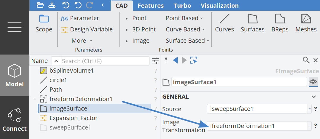
Note that if you now change the original geometry, this will be also transferred to the image before the transformation is applied. For instance, you can change the source geometry (e.g import another geometry and set it at the image) and the whole process chain with your transformations is still valid and will not break.