BRep Morphing in CAESES
The morphing capabilities of CAESES offer a flexible shape modification for both imported geometry, and BReps created in your models. The BRep Morphing allows you to easily manipulate (imported) NURBS based geometries such STEP, IGES, SAT, PARASOLID. In contrast to the Mesh Morphing, it also allows to export the geometry in the same NURBS based format as the import, whereas the Mesh Morph works on the tesselated geometry and therefore the export can only be a tesselated format such as STL as well.
Basic Concept
You can find more general information about the RBF Morphing here.
RBF Morphing techniques are a very powerful and easy to use methods to deform imported geometry or BReps in your project. Internally the geometry will be morphed according to a deformation field. And within a defined tolerance the geometry is modified in a way to match the deformation field, as illustrated by this simple example:
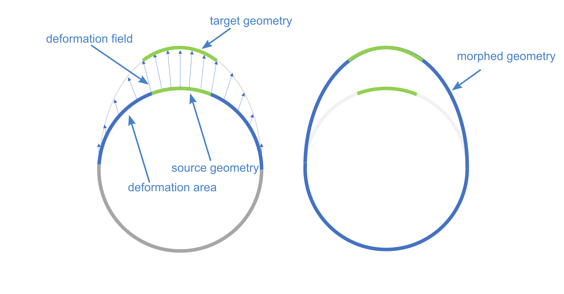
The BRep Morphing will work as shown in the image above. To deform the geometry it needs a source (reference) and a target object. These objects can be Points, Curves or Surfaces. When to use one of these objects depends on how much you want to control the shape of the target geometry. In case you want the geometry to follow a certain guideline, you would choose a curve for source and target. If you simply want to deform the geometry in certain areas, you could use points. If you want to keep the shape of a certain part of the geometry but also want to move it inside the deformation area (rigid motion), you can use surfaces.
- Start a new CAESES project
- Save the project via Menu > File > Save Project As.
Let's set the units of the project. This is useful for file exchange (import and export), since the units are written in files like STEP, IGES or PARASOLID.
- In the File tab select the project node:
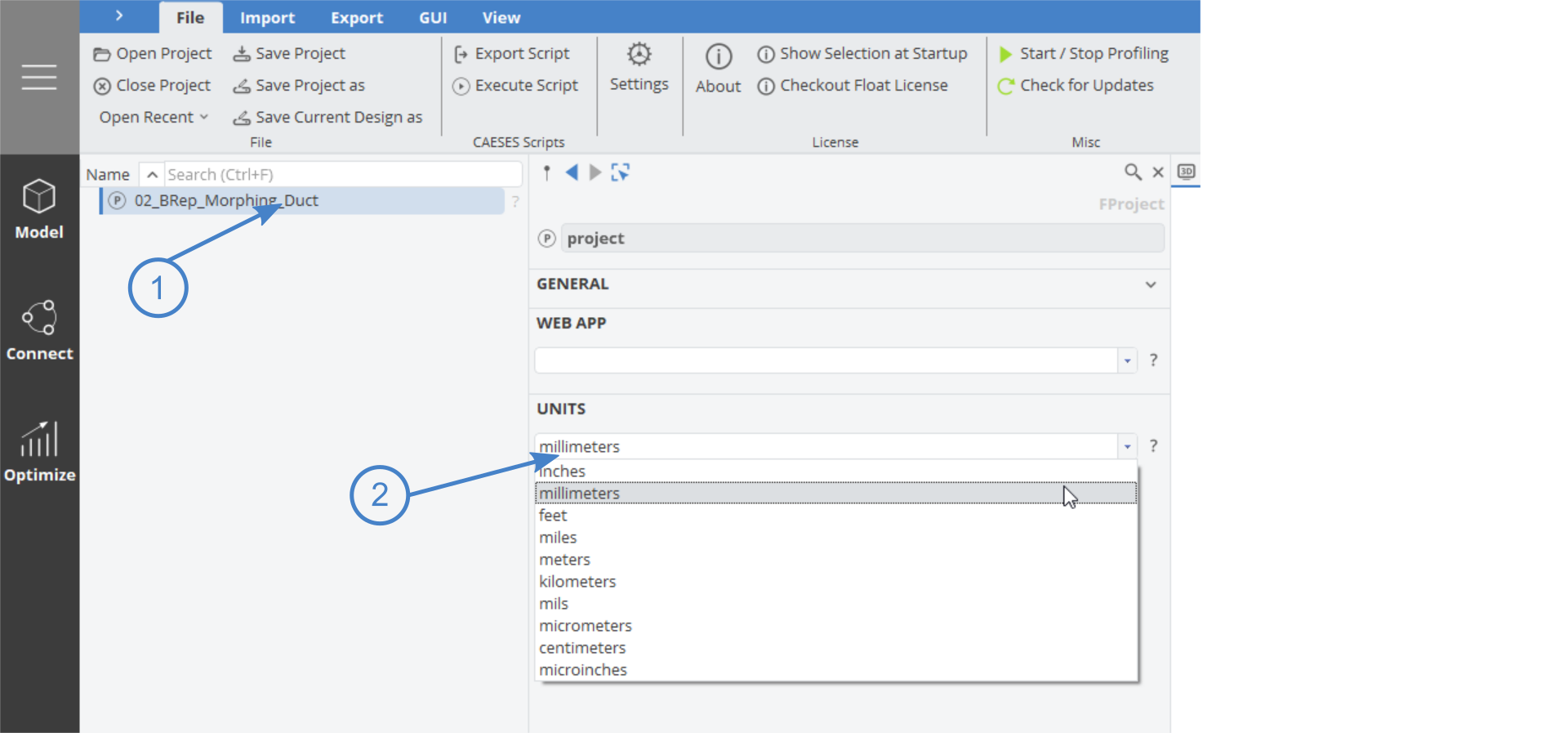
- Set the units to millimeters.
Import Geometry
Let's get started by importing the geometry in STEP format.
- Save the STEP file:
- Go to the Menu workspace and switch to the Import tab.
- Choose STEP and locate the recently saved file
duct.step - Click Open to open/import the file into CAESES
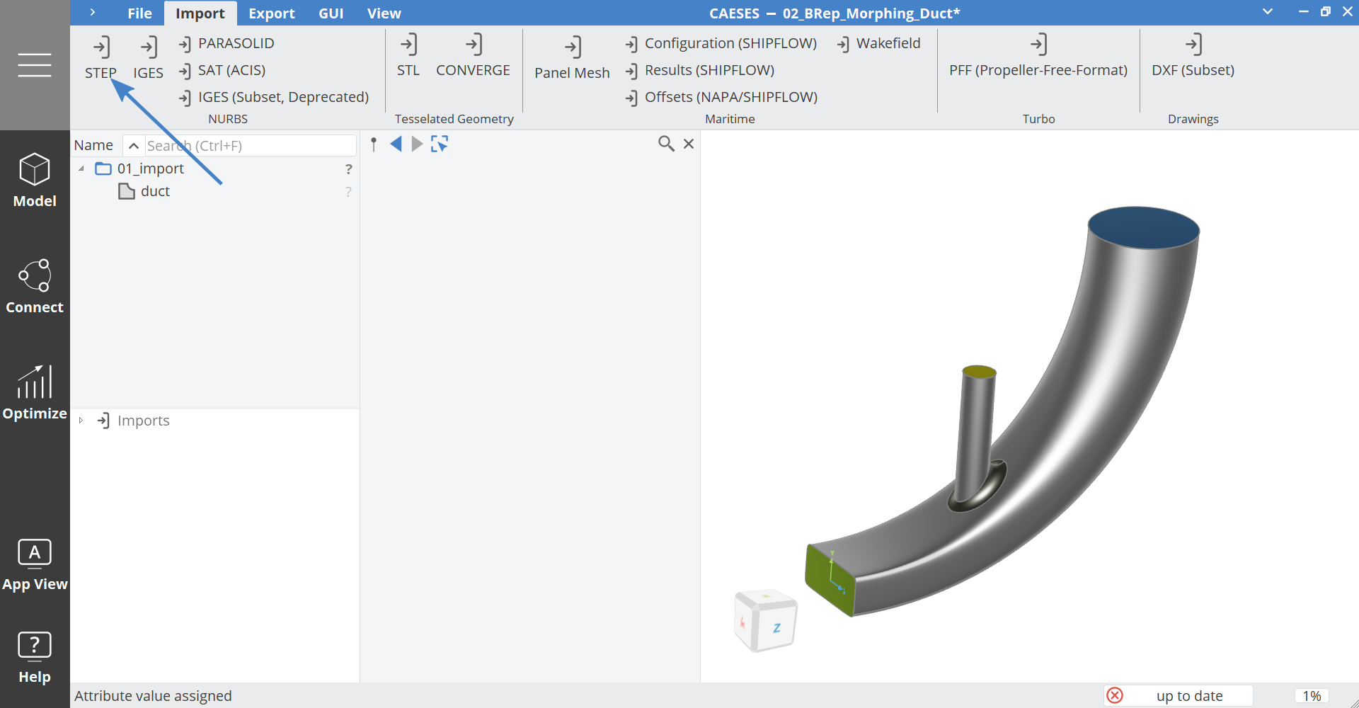
- Switch the workspace to Model > CAD.
- Click on the scope duct and set the name to "01_import".
BRep Morph Overview
Let's create a BRep Morph object and get familiar with some basics.
- Create a BRep Morph object via Model > Transformations > Morphing > BRep

- Set the name of the new BRep Morph object to "ductMorphed".
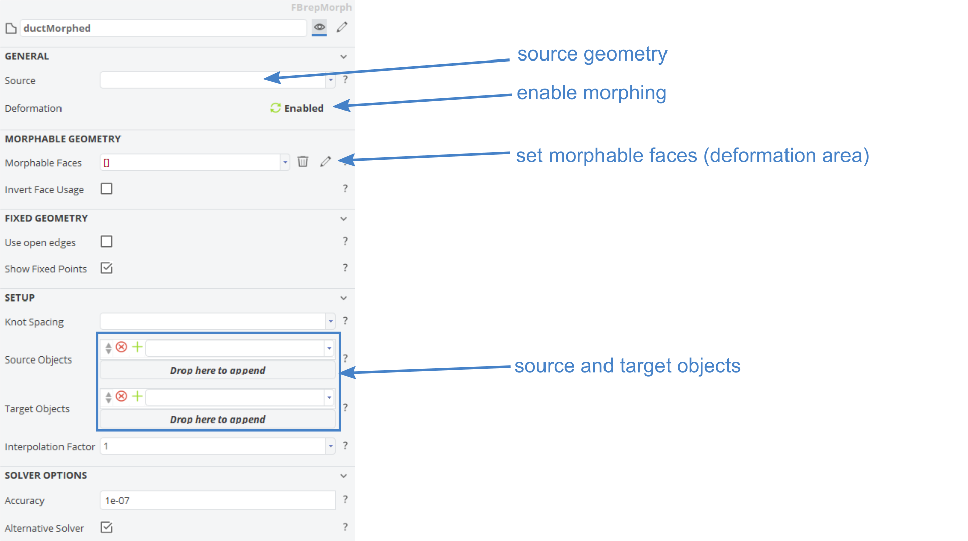
Here is an overview of the BRep Morph editor with the most important options shown:
Prepare the BRep Morph Object
Source
First of all we have to set the geometry which we want to deform.
- Select the object ductMorphed.
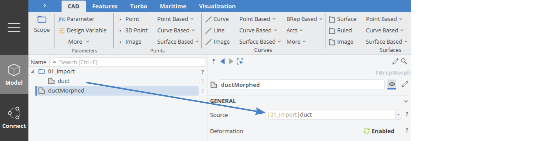
- Drag and drop the BRep duct into the source field:
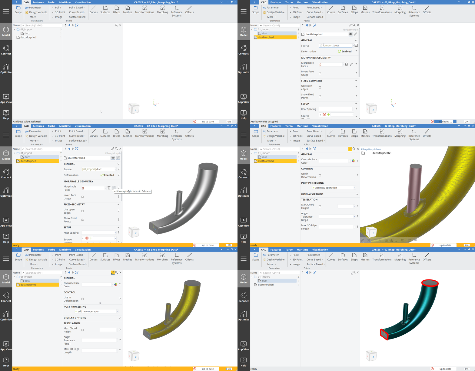
Morphable Faces
- Hide the first scope 01_import with a click on the scope icon.
- Click on the edit button (pen icon) next to the object name or on the right of Morphable Faces to enter the edit mode:
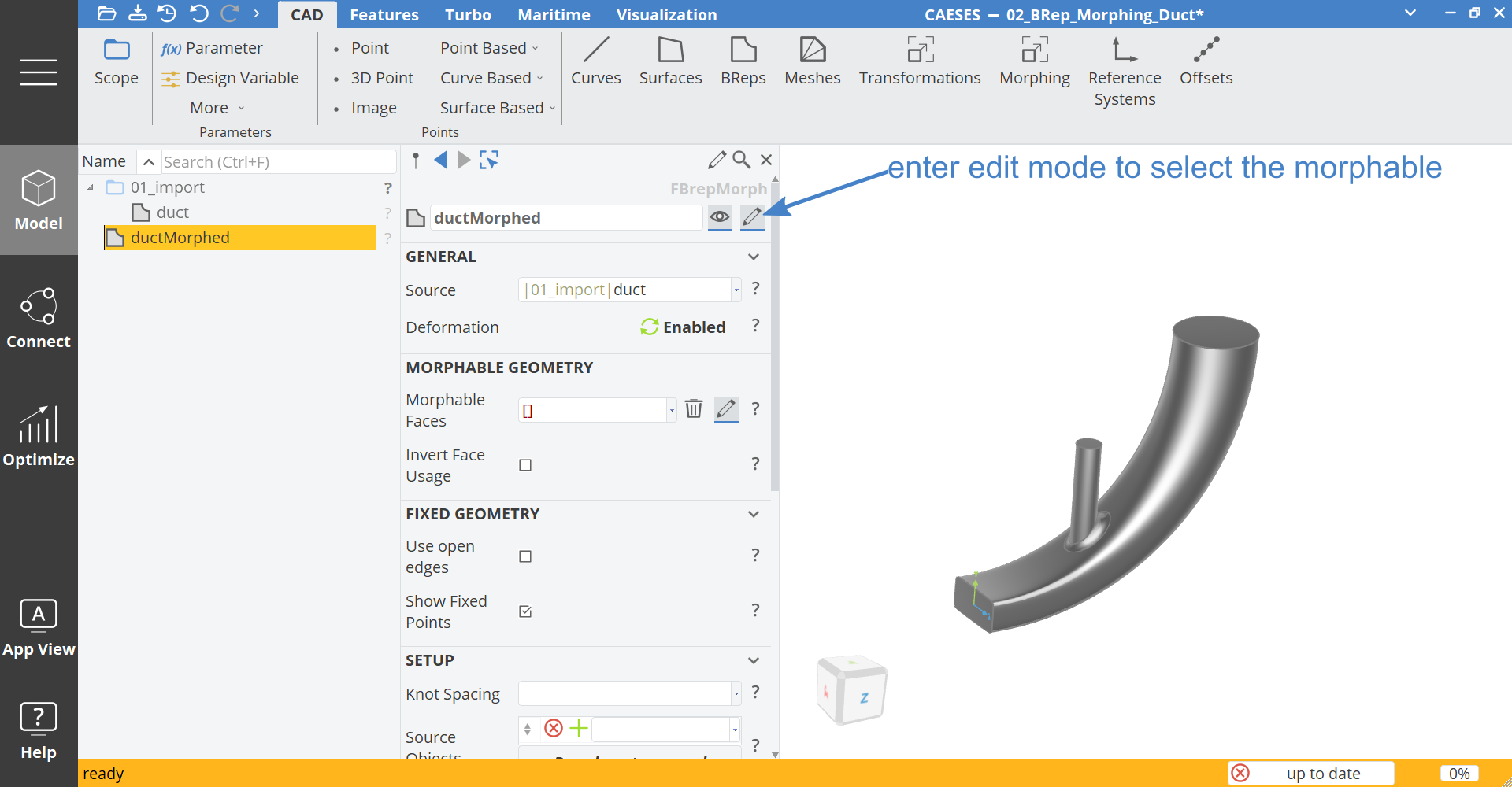
The edit mode is indicated with the yellow/orange status bar.
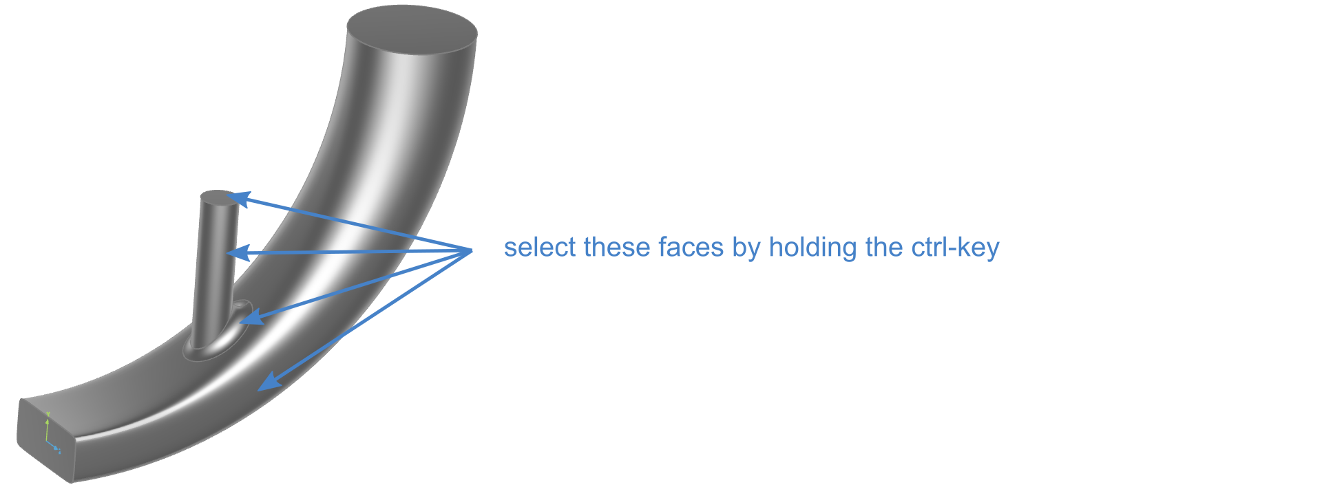
- Select the following faces, while keeping the Ctrl key pressed.
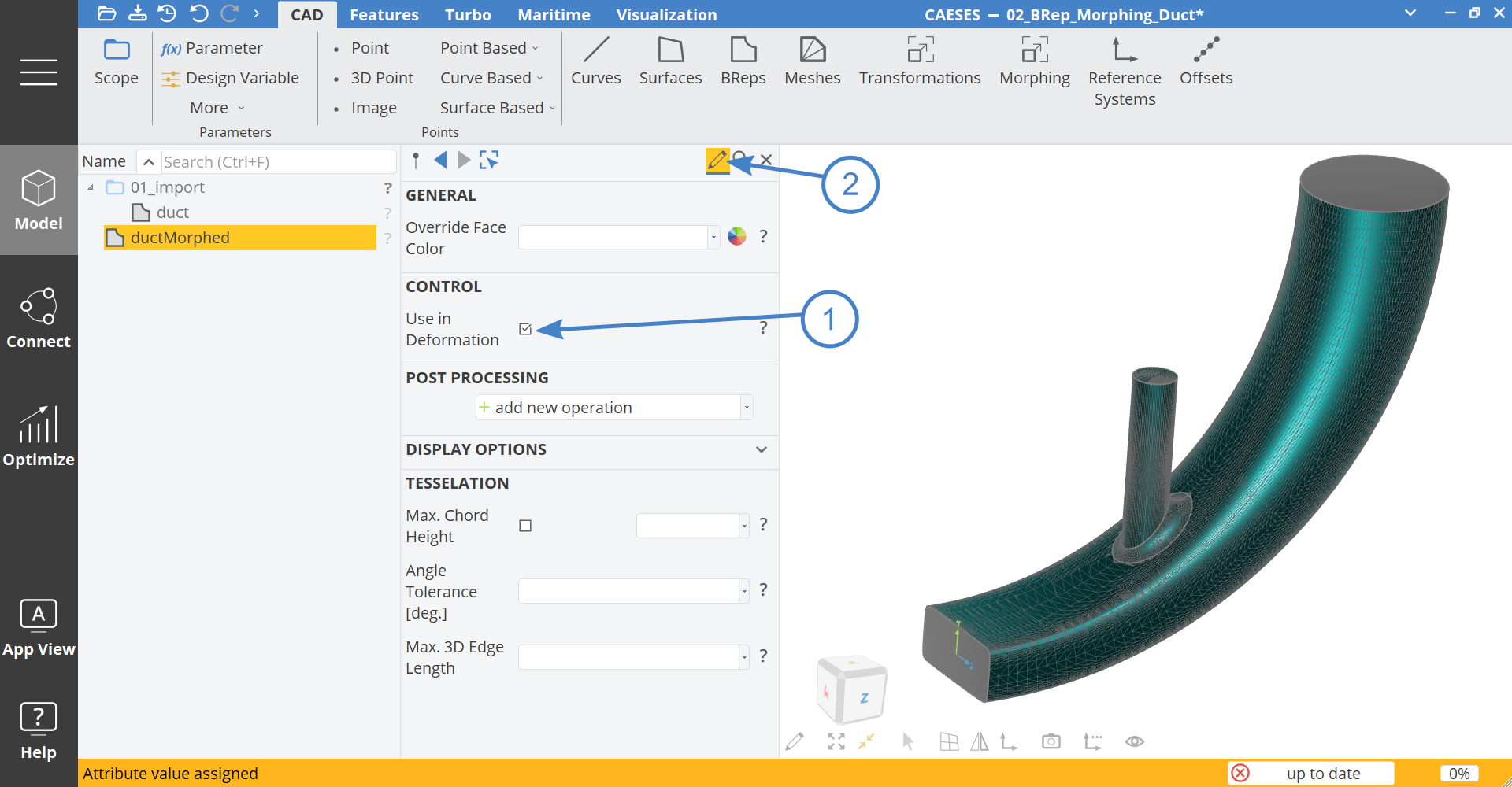
- While the faces are selected, click in the editor on Use in Deformation (1) and leave the edit mode (2):
Here is a video which shows the process of selecting the faces:
Control Polygon and Knot Spacing
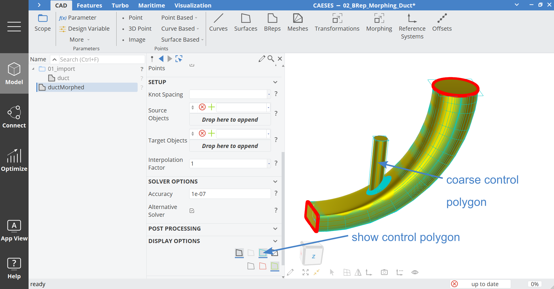
The BRep Morphing works on the basis of the underlying NURBS geometry. If the NURBS geometry knot distribution (also called Control Polygon) is too coarse, the RBF morphing might not work as expected. There is an easy way to visualize the control polygon:
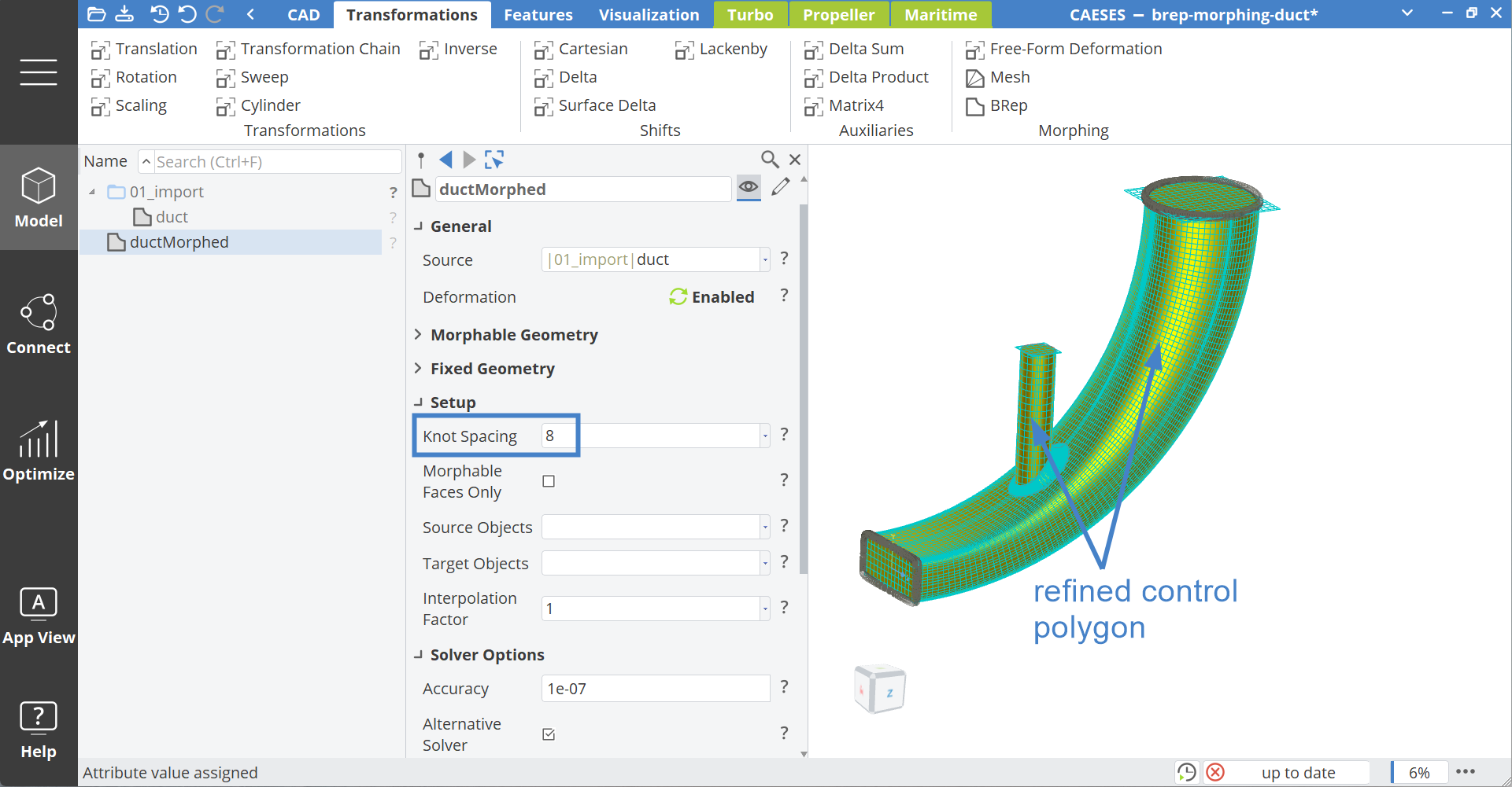
In order to refine the control polygon of the underlying NURBS knots on the surfaces of the BRep, we can adjust the Knot Spacing. Check the BRep Refinement section on Knot Spacing for more information.
- Set the Knot Spacing to
8.
Accuracy
In order to match source and target geometries precisely, we can adjust the accuracy.
- Set the Accuracy (in Solver Options) to
1e-10.
Region 1 - 3DPoints
To define source and target geometries we need to see and reference these on the original imported geometry.
It is a common issue that a source or target geometry is referenced to the BRep Morph object itself by mistake and therefore will result in an infinite recursion, if they are used again in the BRep Morph object.
Make sure to define your source and target objects without dependencies on the BRep Morph object.
- Hide the object ductMorphed and show the scope 01_import with a click on the icons.
- Create a new scope via Model > CAD > Scope.
- Set the name to "02_region1" and make it the working scope with a click with the middle mouse button on the scope icon.
Let's create a point on the surface of the imported BRep.
- Select the BRep duct.
- Hold the Shift and Alt key and click with the left mouse button on the surface to create this point:
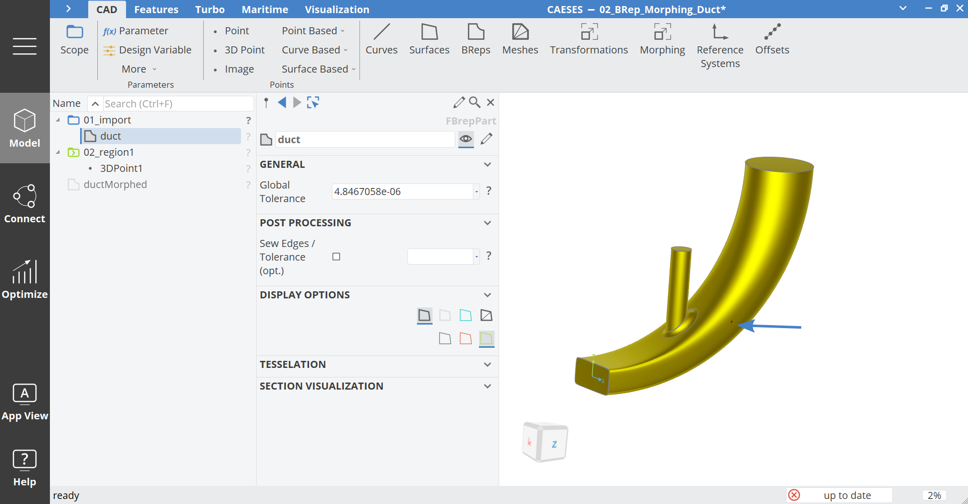
You can create points with this method on Curves, Surfaces, BReps and Trimeshes.
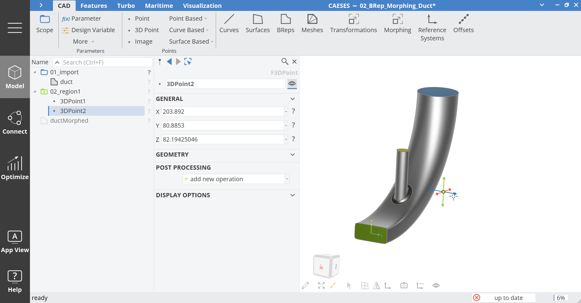
- Select the point Point1, hold the Ctrl key and drag the blue Z arrow to the right (positive Z), which will create a new point:
-
Set the Z value of the point to:
point1:z + 30 -
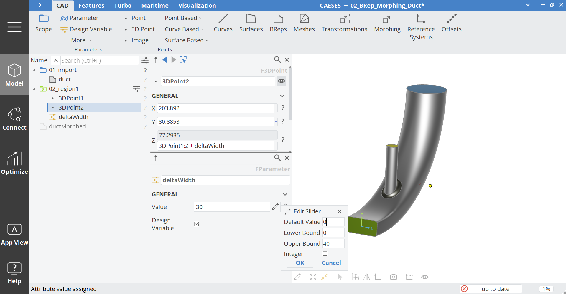
Select the
30right click on it and create a new design variable with the name "deltaWidth". -
Set the default value to
0, the lower bound to0and the upper bound to40:
- Select point1 and set the name to pSrc1.
- Select point2 and set the name to pTrgt1.
Now let's mirror these points to the other side in order to have a symmetric deformation.
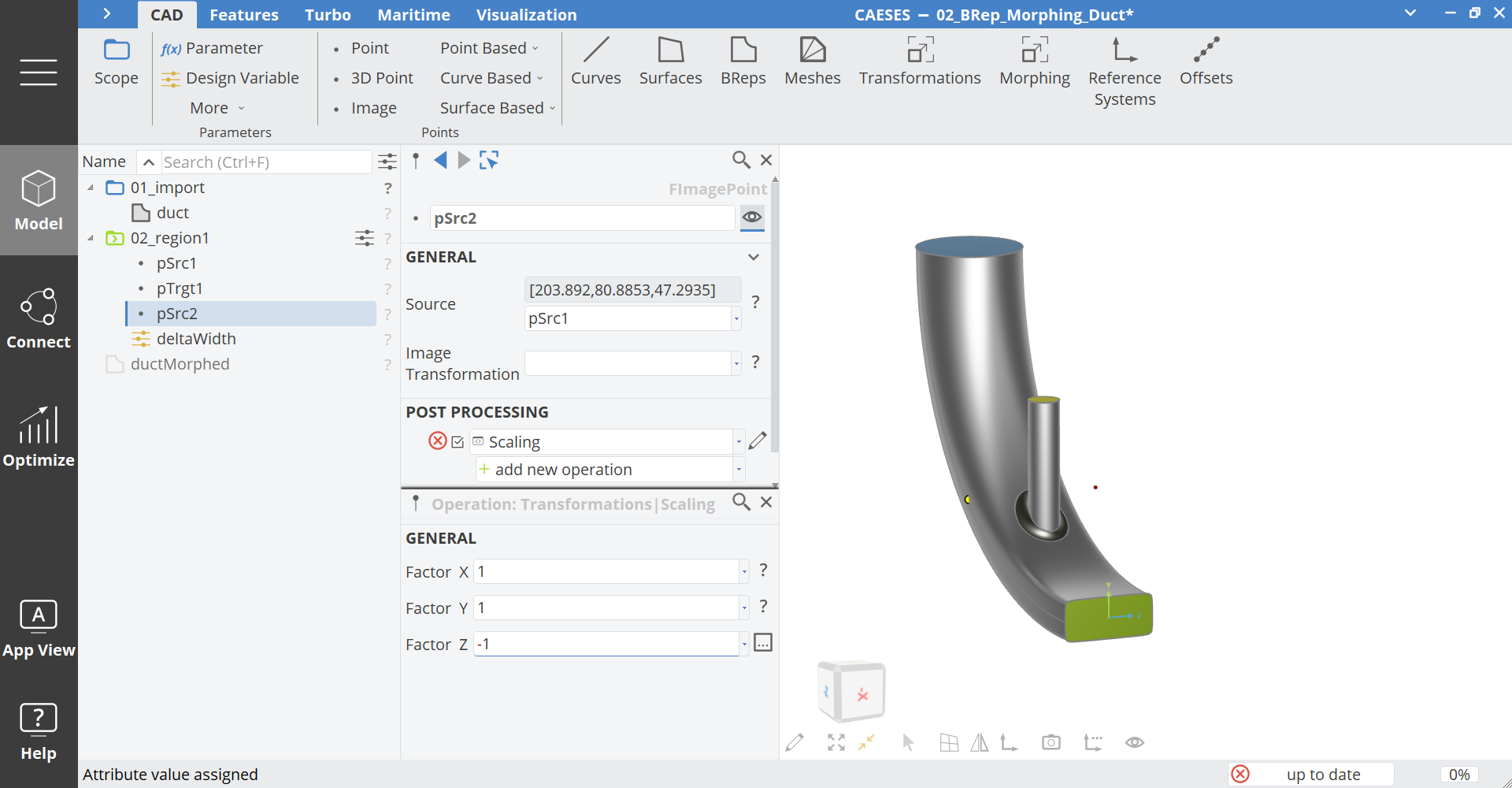
- Select pSrc1 and create an Image Point via Model > CAD > Points > Image Point and set the name to "pSrc2".
- Create the new operation Scaling.
- Set the Z value to
-1
- Copy and paste pSrc2 and set the name of the new point to "pTrgt2".
- Select pTrgt2 and set the Source to pTrgt1. (If the scaling operation does not work, you may have to de-activate and activate the operation again. The problem occurs on pasted objects. We are working on a fix.)
Now let's put these points into the BRep Morph object.
- Hide the scope 01_import and show ductMorphed with a click on the icons.
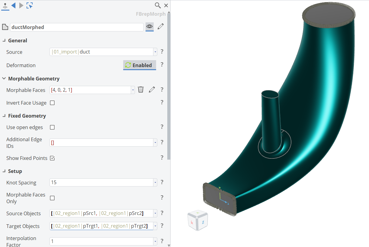
- Drag the point pSrc1 and pSrc2 to the Source Objects field.
- Drag the point pTrgt1 and pTrgt2 to the Target Objects field.
The result for this step should look like this:
Region 2 - Surface based Point
Now we want to create a point on the original duct surface, which is pointing in normal direction to the surface. To achieve this we will extract the surface first and then create the points.
- Hide the object ductMorphed and the scope 02_region1.
- Show the scope 01_import.
- Create a new scope via Model > CAD > Scope.
- Set the name to "03_region2" and make it the working scope with a click with the middle mouse button on the scope icon.
- Hover with the mouse over the surface of the main duct and activate the subselection mode by pressing Ctrl+Alt. This will allow you to pick subelements of the BRep, like the surface.
- While the subselection mode is active (light blue colored geometry and status bar) click on the main duct surface (Face 4). The selection will be highlighted in yellow.
- While the surface is selected, create a new Image Surface via Model > CAD > Surfaces >Surface Based > Image.
- Set the name of the surface surface1 to "ductSurface".
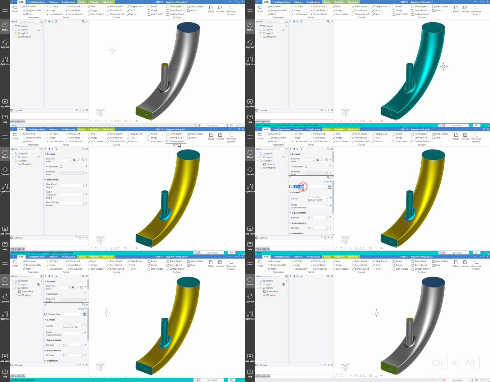
- Hide the scope 01_import.
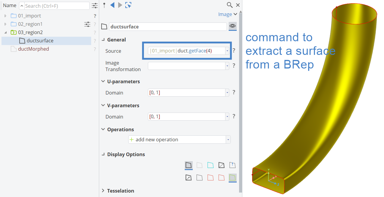
You can see the command to extract the face/surface from the BRep. You can also see that the underlying surface from BRep is not trimmed (the surface does not include the hole from the cylinder intake), which is the basic concept of BReps (or Boundary Representation). The trimmed faces in BReps are defined by the trim curves on the surface.
Now let's create a source and a target point, which are defined normal to the surface.
-
While the surface ductSurface is selected, create a new point via Model > CAD > Points > Surface Based > Normal to Surface.
-
Set the name of the point point1 to "pSrc".
-
Set U Position to
0.75. -
Set Distance to
0.
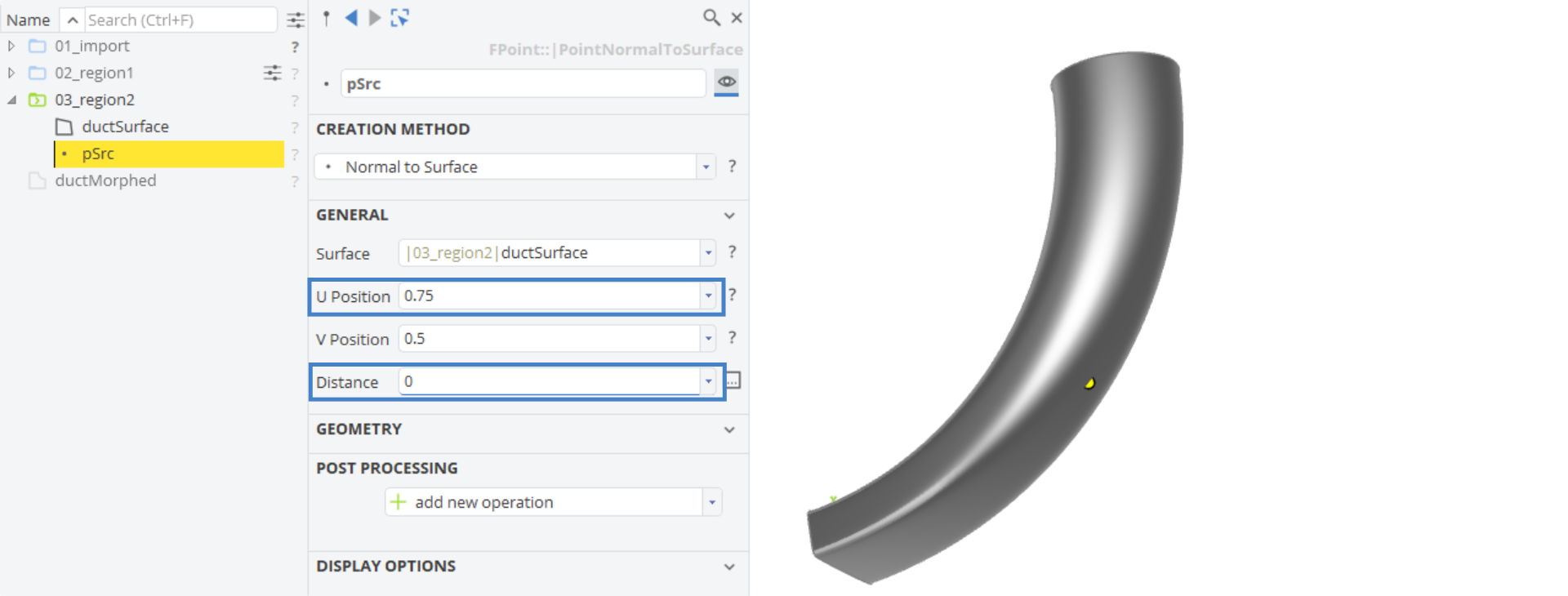
The advantage of the Point Normal to Surface in comparison to the 3DPoint in region1 is, that it is located on the surface and described with u- and v-position, which could be varied with Design Variables. Additionally, the direction is defined by the surface normal instead of 3D coordinates.
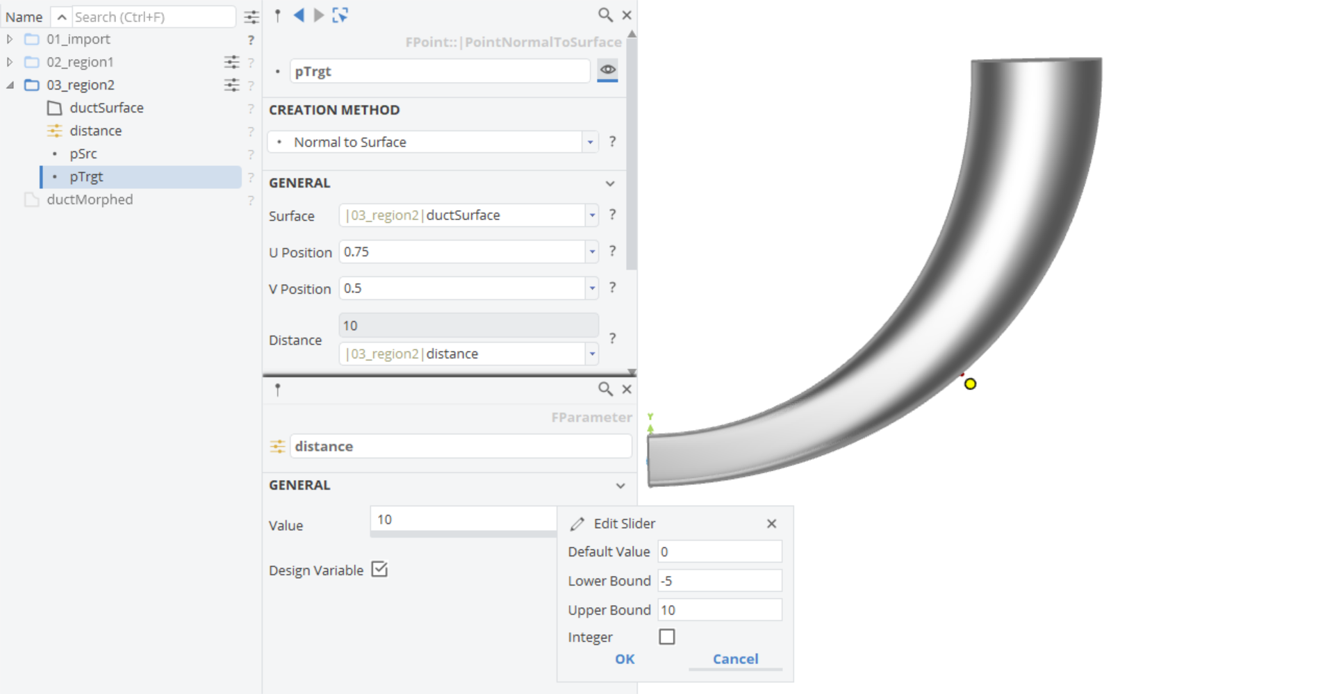
- Copy and paste pSrc and set the name of the new point to "pTrgt".
- Select pTrgt.
- Right click on the value
0of Distance and create a new Design Variable. - Set the name of the Design Variable to distance.
- Click on the edit button next to the Design Variable value.
- Set the Lower Bound to
-5and the Upper Bound to10.
- Click with the middle mouse button on the scope 03_region2 so that this will not be the working scope anymore.
Now let's include these points to the object ductMorphed.
- Show and select the object ductMorphed.
- Drag and drop the point pSrc from scope 03_region2 to the Source Objects.
- Drag and drop the point pTrgt from scope 03_region2 to the Target Objects.
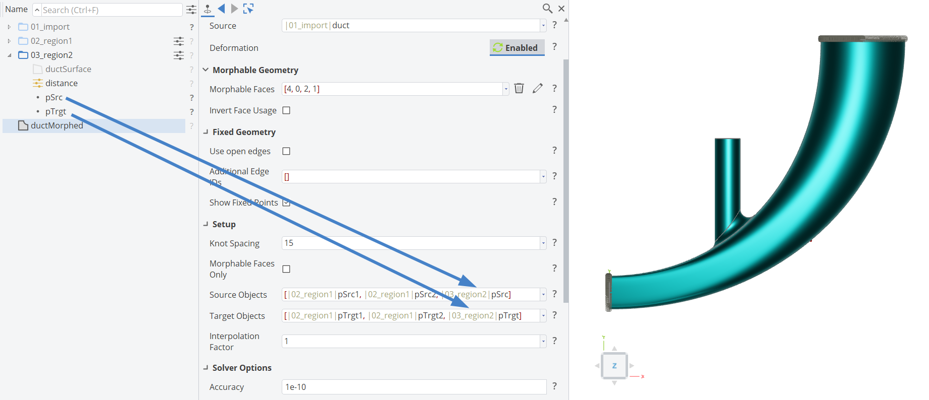
Now you can modify the Design Variable Distance and observe the result.
Region 3 - Surfaces
As a third example we will use surfaces as sources and targets in order to fix the shape of the intake duct and move the position of it.
- Create a new scope via Model > CAD > Scope.
- Set the name to "04_region3" and make it the working scope with a click with the middle mouse button on the scope icon.
- Hide the object ductMorphed and the scope 03_region2.
- Show the scope 01_import.
- Hover with the mouse over the 01_import|duct BRep and activate the subselection mode by pressing Ctrl+Alt. This will allow you to pick subelements of the BRep, like the surface.
- While the subselection mode is active (light blue colored geometry and status bar) click on the intake cylinder surface (Face 2). The selection will be highlighted in yellow.
- While the surface is selected, create a new Image Surface via Model > CAD > Surfaces >Surface Based > Image.
- Set the name of the surface surface1 to "src1".
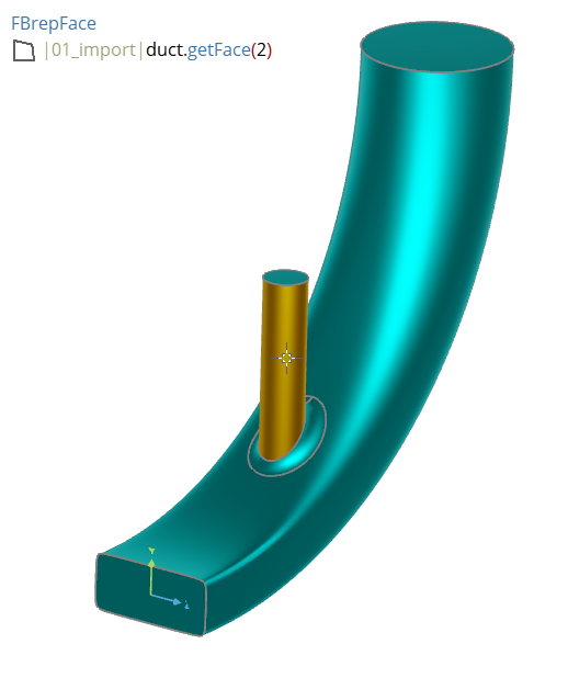
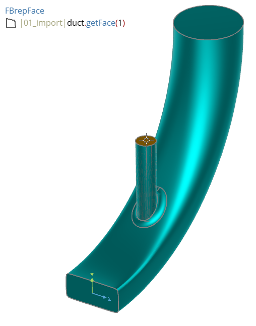
- Select the surface 01_import|duct.getFace(1).
- While the surface is selected, create a new Image Surface via Model > CAD > Surfaces > Image.
- Set the name of the surface surface1 to "src2".
-
Exit the subselection mode by pressing Ctrl+Alt
-
Select src1 and src2
-
Copy and paste the surfaces.
-
Rename the surface src3 to "trgt1".
-
Rename the surface src4 to "trgt2".
-
Select trgt1 and add the new Operation Transformations > Translation.
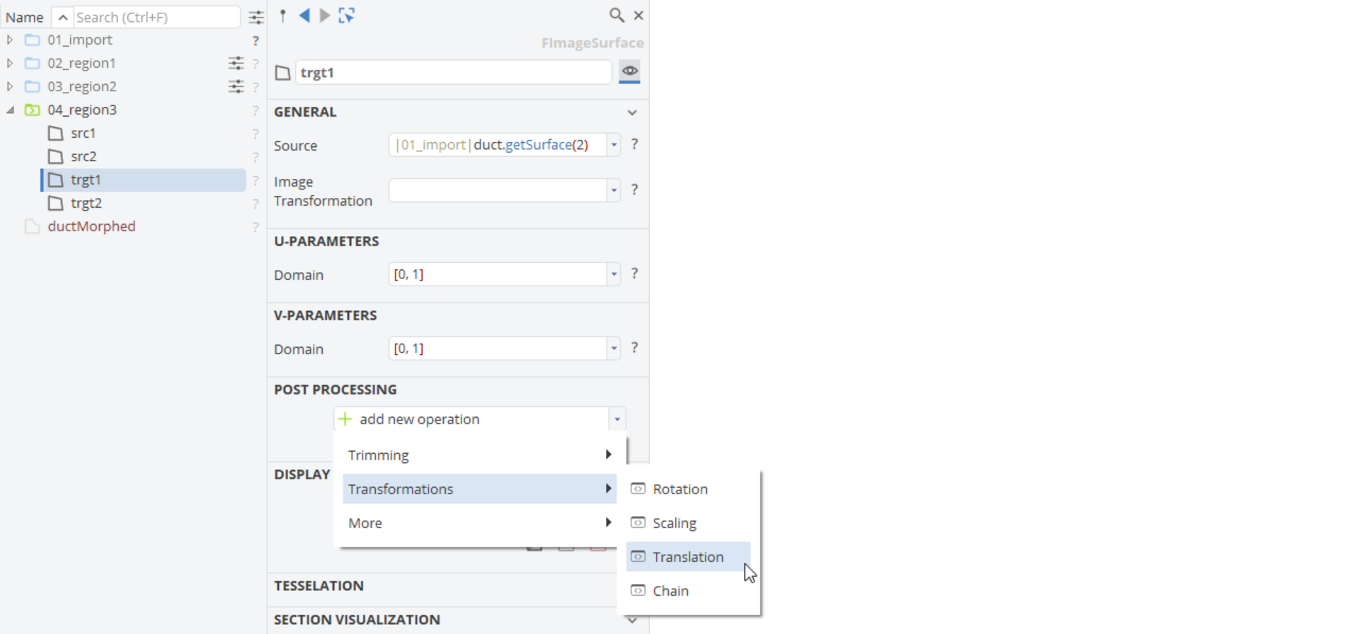
- Right click on the
0value of Dy and create a new Design Variable. - Set the name of the Design Variable to "dY".
- Set the Default Value and the Lower Bound to
0and the Upper Bound to15.
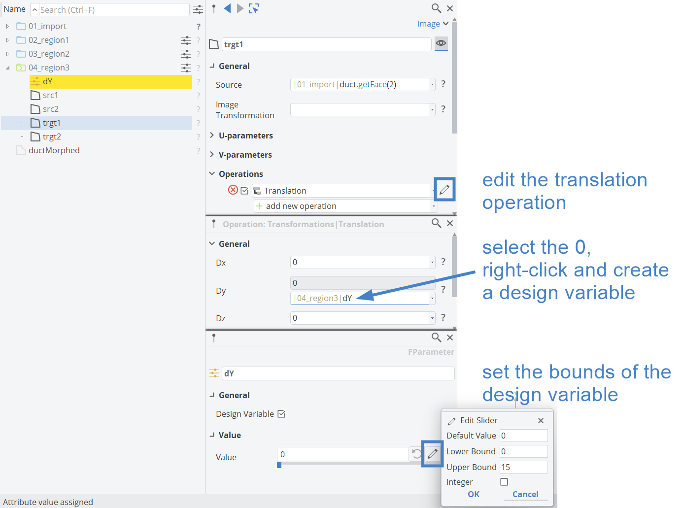
- Select trgt2 and create add the new operation Transformations > Translation.
- Use the Design Variable dY in the Dy value of the translation operation. You can do this via drag and drop.
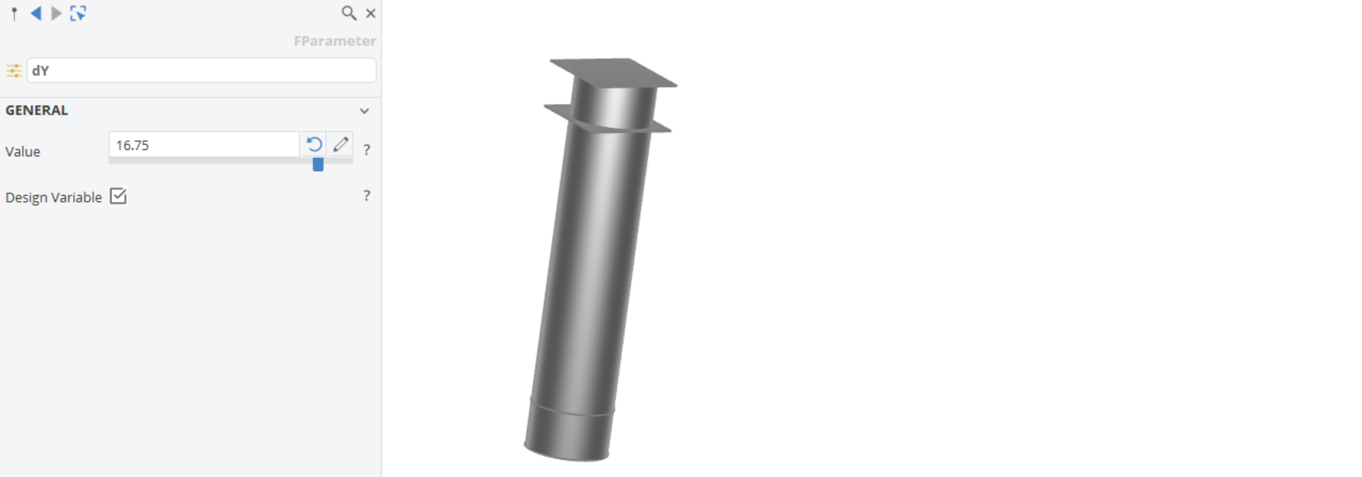
The resulting surfaces are shown in the image below:
Now let's include these surface in the BRep Morph object.
- Hide the scope 04_region3.
- Make the BRep Morph object ductMorph visible.
- Select ductMorph.
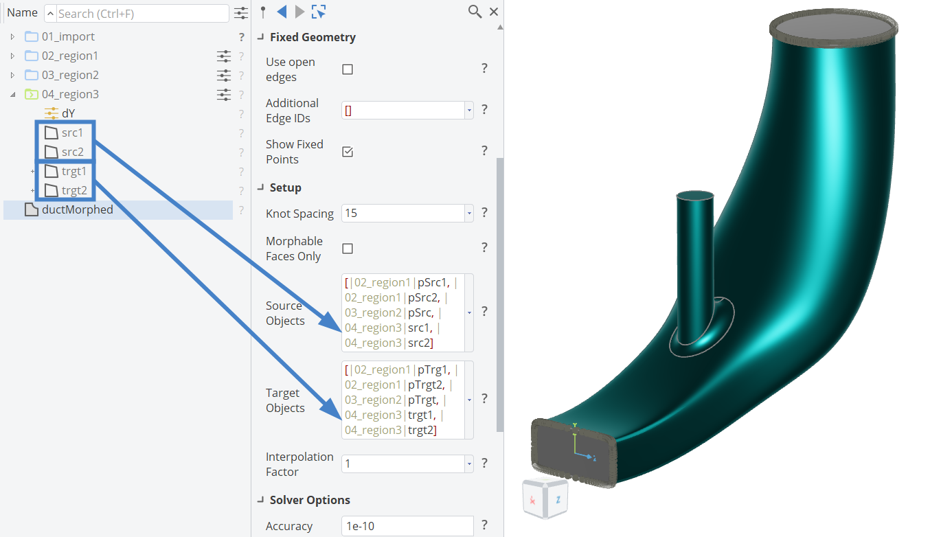
- Drag and drop the two surfaces src1 and src2 from the scope 04_region3 to the Source Objects.
- Drag and drop the two surfaces trgt1 and trgt2 from the scope 04_region3 to the Target Objects.
The final result is shown in the image below:
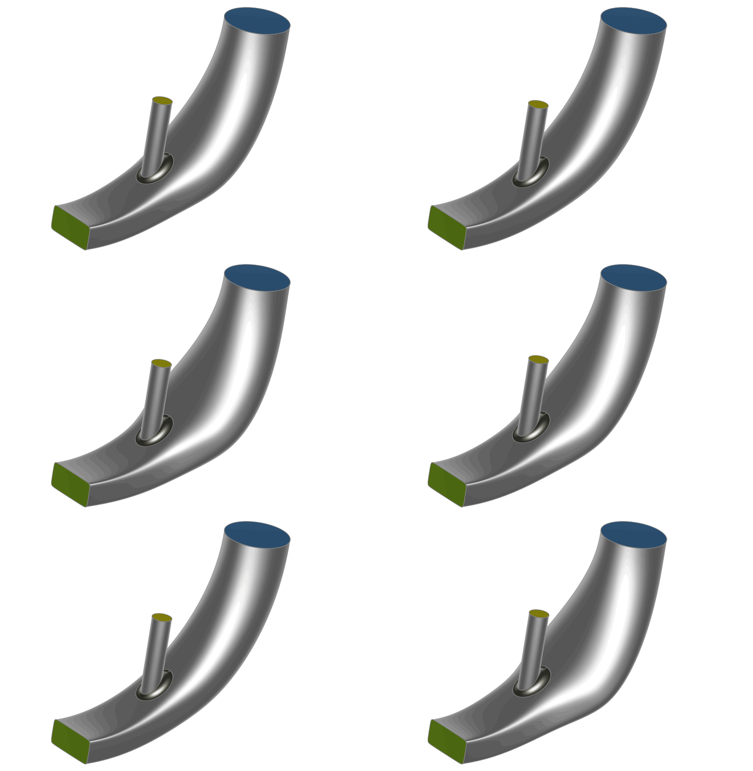
You can now manually adjust the design variables, or create a variation of the geometry with a Sobol Design Engine:
In order to see the original colors of the duct, you can select the BRep Morph object and create a new BRep from it (the BRep Morph is automatically added as a source for the new BRep). When you hide the BRep Morph object (by clicking on the BRep Morph icon in the tree), you see the new BRep with the original colors.
CAESES Project File
If you want to take a look at the finalized model you can find the resulting CAESES project file brep-morphing-duct.cdb here: