Free-Form Deformation of a Bulb
With the Free-Form Deformation (FFD) it is possible to vary the shape of your geometry in an intuitive manner with just a few clicks. This tutorial will guide you step-by-step through the creation of a simple Free-Form Deformation. First we will create a deformation box around the geometry, and then set up different operations for the deformation.
The idea of the Free-Form Deformation is to control the position of a set of points inside a particular volume and have the geometry within this volume follow these changes in a smooth manner.
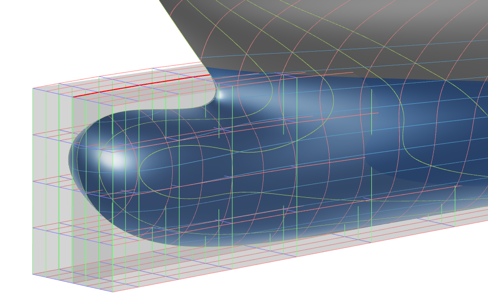
Deformation Box
Start by opening a project that already contains a geometry you wish to modify. After some initial book keeping (Scopes with leading numbers are always a good choice to structure a project) we will start by setting up a reference surface for the Deformation Box (the volume within which we define the shape changes later on).

Hold down Ctrl while dragging a point to create a copy on the fly.
From Model > CAD > Transformations > Free-Form Deformation we will create a new Free-Form Deformation, generate a new Deformation Box and choose the Offset Surface method. Specify the number and position of offsets as needed.

Transformations
There are different transformations readily available to use with the Free-Form Deformation. The simplest option is to choose a translation and simply assign an offset in x-, y- and z-direction to a group of points.
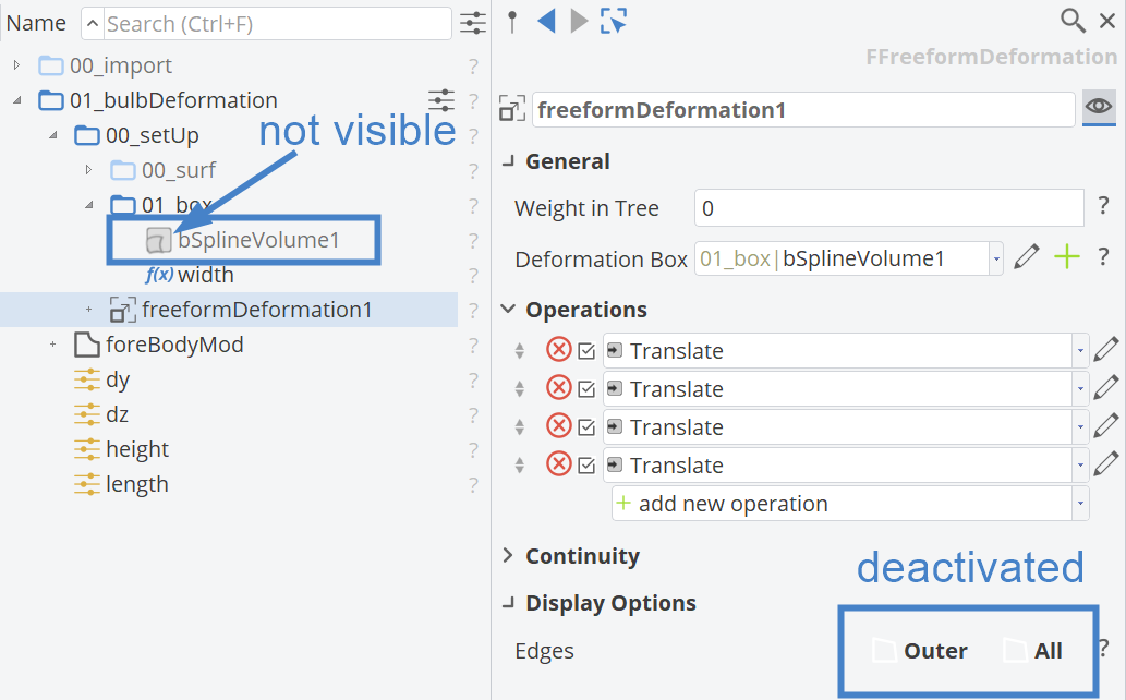
Selecting the points where the deformation is applied, gets easier if you:
- hide the B-Spline volume from the 3D view (click on the icon of
bSplineVolume1in the object tree) - deactivate the Edge Display for Outer and All edges of the
freeformDeformation1

It is good practice to "fade out" a translation as shown in the animation. The translation in y-direction is specified twice: once for a set of points receiving the value of the Design Variable dy and once for a set of neighboring points receiving only a fraction of the value such as to blend in the shape changes more easily.
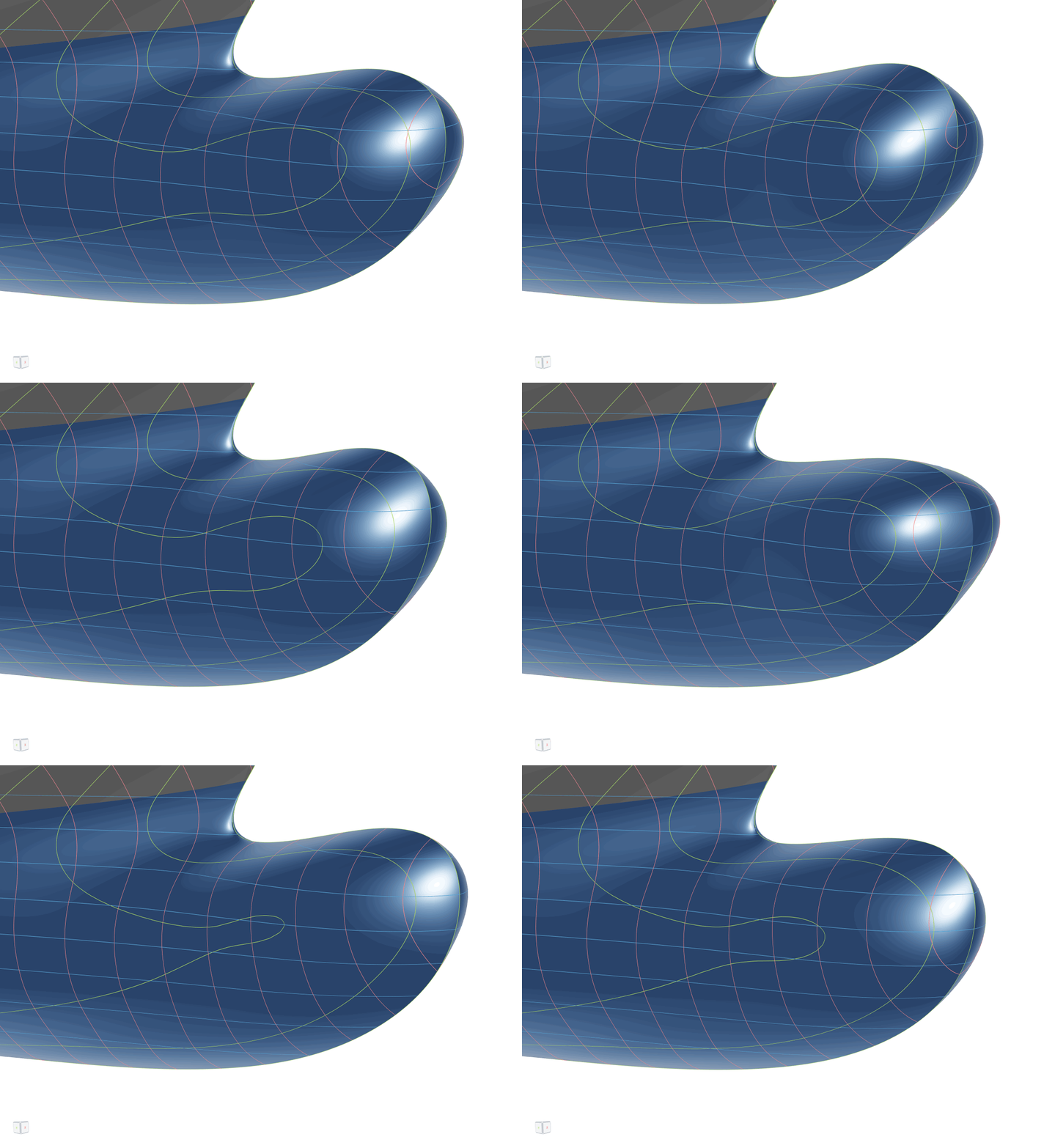
Keep adding transformations and introducing new Design Variables as needed to accommodate all the shape variations desired for an optimization. In the present example a vertical change in center of buoyancy has been added by shifting the same selection of points as before in vertical direction. In addition, a vertical and longitudinal shift are introduced to change height and length of the bulbous bow (bulb).
Note how the parametrization of the curve that was used to model the Deformation Box can be used to change the spacing of control point layers in the Box.

Design Space and Robustness Check
The combined design space can be visualized by running a small Design of Experiments i.e. a Sobol algorithm to get a better visual understanding of the shapes as well as to assess the robustness of the model.
CAESES Project File
If you want to take a look at the finalized parametric model you can find the resulting CAESES project file free-form-deformation-bulb.cdb here: