Volute Design
This tutorial guide gives you an overview how to model volutes in CAESES. For a concept-level introduction, see the Volute Design documentation.

The workflow is typically divided into the following main steps:

Volute Section
The parametric volute surface is mostly created with a meta surface. This gives you detailed control of the individual parameters over circumferential coordinates with the help of 2D functions. The prerequisite for the meta surface is a feature definition of the volute section.
To get general and detailed information about feature definitions, please see the chapter Features.
Here you can find some simple feature definitions for volute cross sections:
Volute Section 1

Click here to download the feature definition and drag and drop it into your project (you will find it under Model > Features):
Download Profile Cross Section 1Volute Section 2

Click here to download the feature definition and drag and drop it into your project
Download Profile Cross Section 2Volute Section 3

Click here to download the feature definition and drag and drop it into your project:
Download Profile Cross Section 3Tips and Tricks
Creating a simple 2D section
The following code shows how the Volute Section 2 is created. Since we want to rotate the section around the Z-axis, we create the section in the X,Y-plane. The arguments (inputs) of the feature definition are:
- radius
- height
- A2R
- wrapAngle
In the first part of the definition we create the two points at the inlet as a reference. Then we create a temporary circle and transform it to go through the points pu and pl:
point pu(radius,0,height/2)
point pl(radius,0,-height/2)

designvariable d(height*2)
parameter rc1(d/2)

rotation rotX(90,0)
parameter dx(rc1*(1-cos(asin(height/2/rc1))))
translation transEdge(rc1+radius-dx,0,0)

transformationChain chain1([rotX,transEdge])

circle circ1(){
  .setRadius(rc1)
  .setTransformation(chain1)
  .setVisible(1)
  .setStartAngle(180)
  .setEndAngle(180+360)
  .setConstantAngleSpeed(true)
  .setStipplePattern("dot line")
}
Next we need to trim the circle at the upper point pu and the lower point pl. To this end we calculate the relative positions t on the curve, which are closest to the points. These are then used to calculate the start and end angle of the circle:
// calc relative position closest to pu and pl
parameter posL(circ1.getParameterShortestDistanceSquared(pl))
parameter posU(circ1.getParameterShortestDistanceSquared(pu))

// calculate the start and end angle on the circle
parameter angle1(posL*360)
parameter angle2(posU*360)

// create the new "trimmed" circle
circle section2D(){
  .setRadius(rc1)
  .setTransformation(chain1)
  .setVisible(1)
  .setStartAngle(180+angle1)
  .setEndAngle(180+angle2)
  .setStipplePattern("dot line")
}
Now we could use this curve and rotate it around the z-axis with the wrap angle:
rotation rotZ(wrapAngle,2)
imagecurve profile_3D(section2D,rotZ)
But in most cases we would have to adjust the area of the curve to meet a target A/R ratio. How to achieve this will be shown in the next chapter.
Calculating the A/R ratio
An essential parameter in volute section design is the A/R ratio. This parameter describes the ratio of the cross-sectional area (A) to the radius of the centroid (R):

In order to match the target A/R ratio, we need to define a free design variable in the feature definition. This free design variable can be for example a certain diameter or a length. Let's assume we want to meet the target A/R ratio of the section shown above; here we would define the diameter d as a free design variable:

This short code snippet shows how the design variable D is optimized in order to meet a target A/R ratio:
// calculate A2R
// close curve in order to calculate the center of gravity (COA)
line lc(section2D:end,section2D:start)
polycurve profileMeasured([section2D,lc]).setAutomaticOrientation(1)
point coa(profileMeasured.getCOA(1))

// calculate parameters
parameter area_is(abs(profileMeasured.getArea(0,1)))
parameter radius_is(coa:x)
parameter a2R_is(area_is/radius_is)
parameter objective(abs(a2r-a2r_is)^2)

// set reasonable upper and lower bounds for design engine
double lb(height*0.1)
double ub(height*10)

// run design engine to minimize the objective parameter
de_brent opti(){
  .setNumberOfIterations(40)
  .setDesignVariables([[d,lb,ub,true]])
  .setEvaluations([[objective,true]])
  .run()
}
Volute Surface
Using the Volute Section 3 Feature Definition from the previous section, we can create a Volute Surface. Let's use profile definition 3 for the next steps:
To get more familiar with Meta Surfaces, please refer to the tutorials in Introduction to Meta Surfaces.
From the tutorials we know that we need a curve engine, which will serve as input for the Meta Surface. The input of the curve engine is the feature definition of the volute section. The base curve is the 3D curve of the feature definition, which is rotated around the Z-axis. You can put constant parameters as arguments or define 2D functions as circumferential distributions. From our example we would for example create a linear distribution for the wrap angle and a parametric curve for the A/R ratio.
- Start with a new project.
- If you haven't done so yet, download the "Profile 3 Cross Section" and import the feature definition
voluteProfile_profile3.fdf(drag and drop it into the project or import it in the Model > Features tab).
- Create a scope via Model > CAD > Scope, set the name to "01_VoluteSurface" and make it your working scope.
Curve Engine
- Create a new Curve Engine via Model > CAD > Surfaces > Meta Surface > Curve Engine.
- Set the feature definition voluteProfile_profile3 as the definition.
- Make sure that the base curve is profile_3D and the Coordinate System is in Z-(X,Y) plane, which means that your parameter distributions are created in this plane.
Parameter Functions
Now let's create some parameter functions, which control the parameters along the sweep direction.
- Create a scope via Model > CAD > Scope, set the name to "functions" and make it your working scope.
- Open the 3D Overview window by clicking with the right mouse button on the black workspace bar (on the left) and select 3DOverView.
- In the 3D Overview window activate the filters with a click on the eye button.
- Inside the filter toolbar, click on the Search button and set the name filter to "functions". This will only show objects which are located in the scope functions.
- Create a 2D Diagram via Model > Visualization > 2D Diagram.
- Set the Name X Axis to "sweep position".
- Set the Name Y Axis to "parameter value".
- Deactivate the title.
Our sweep parameter for the Meta Surface is the wrap angle. This means that the surface is swept around the Z-axis. Each parameter distribution is a function of the wrap angle.
- Let's create a linear distribution of the wrap angle. Create a new line via Model > CAD > Curves > Line and set the name to wrapAngle.
- Keep the start position of wrapAngle at
[0,0,0]. This means that at the beginning of the surface (x=0) the wrap angle is zero (y=0). - Keep the end position at
[1,1,0]. This means that at the end of the surface (x=1) the wrap angle is 1 (y=1). Of course we want to have a wrap angle at the end of 360 degree, to achieve this we can scale the function later in the curve engine.
- Keep the start position of wrapAngle at
- Set the line wrapAngle as an argument of the curve engine for Wrap Angle. You can do this for example by drag and drop.
You can see now the expression [wrapAngle,1]. The value 1 is the scaling factor of the function. In our case the y-value of the function will be scaled.
- Set the
1of the expression[wrapAngle,1]to360→[wrapAngle,360]

Now let's create a function for the A2R ratio, which will have the main impact on flow properties. We create a simple BSpline curve, where we can set the angles of the curve.
- Create a new Design Variable with the name A2R_start and set the value to
1. - Create a new Design Variable with the name A2R_end and set the value to
10. - Create a new curve via Model > CAD > Curves > Point Based > Planar with Tangent Control and set the name to A2R_distribution
- Set the arguments as:
- Start Position:
[0,A2R_start/10,0] - Start Angle:
40 - End Position:
[1,A2R_end/10,0] - End Angle:
50
- Start Position:
- Create a new Design Variable for the start angle by right clicking on the value
40and setting the name to A2R_angle_start. - Create a new Design Variable for the end angle by right clicking on the value
50and setting the name to A2R_angle_end.

- Set the curve A2R_distribution to the argument A2R of the curve engine and set the scaling factor from
1to10.
Let's keep the other arguments of the curve engine constant along the wrap angle. Therefore we just have to set constant values.
- Create a new Parameter with the name Radius, set the value to
50and set it to the curve engine argument Radius. - Create a new Parameter with the name Height, set the value to
6and set it to the curve engine argument Height. - Create a new Design Variable with the name Ratio, set the value to
1.3and set it to the curve engine argument Ratio. - Create a new Design Variable with the name AngleStart, set the value to
0and set it to the curve engine argument Angle Start. - Create a new Parameter with the name FilletRatio, set the value to
0.6and set it to the curve engine argument Fillet Ratio.

Final Meta Surface
Now the setup of the curve engine is done and we can create the Meta Surface.
- Set the scope 01_voluteSurface as your working scope.
- Select the Curve Engine.
- Create a Meta Surface via Model > CAD > Surfaces > Meta Surface > Meta Surface and set the name to voluteSurface.
- In the 3D View click on a face of the cube to zoom to the current selection.
")
Diffuser Surface
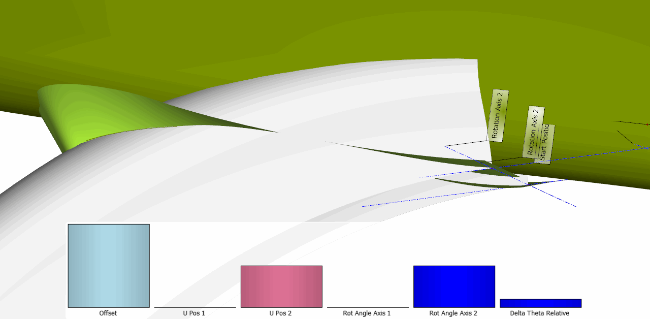
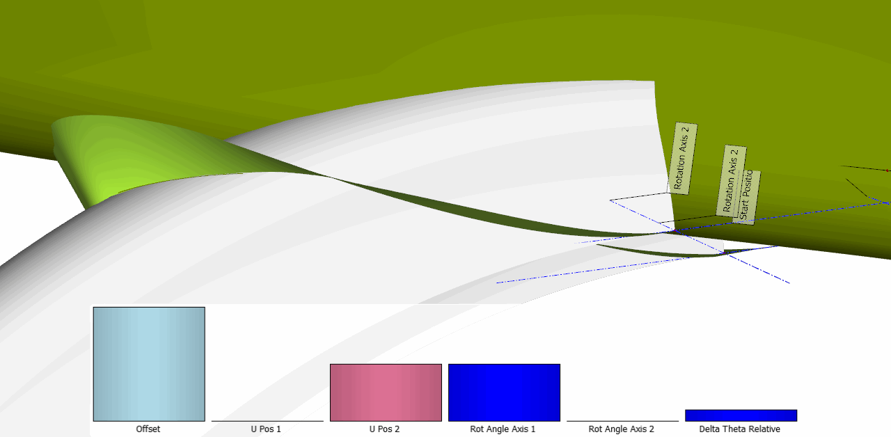
In this step we need to blend from the volute section to a circular section at the outlet. This can be done with the following feature definition:
Download Diffuser Feature- Create a new scope via Model > CAD > Scope and set the name to "02_diffuser" and make it your working scope.
- Switch the tab to Model > Features.
- Right click on the feature definition Volute_Diffuser and create the feature. Set the name to "DiffuserSurface".
- Set the arguments as:
- From:
- Volute Surface:
VoluteSurface(from the first scope) - U Start:
0.02 - U End:
0.98
- Volute Surface:
- To:
- Length:
100 - Delta Vector:
[10,0,0] - Radius:
20 - Rotation Angle:
-30
- Length:
- From:

In the following sections we will go through some main arguments of the feature.
Volute Surface
Here you put the volute surface. With the toggle Section at V1 you can set at which V position the diffuser surface will attach.
U Start & U End
Defines the U positions where the profile of the volute will be closed. The label Start Position and End Position will visualize this positions.
Tangent Factor
Defines the strength of the tangency at the volute and at the outlet.
Normal to Start Plane
This option will set the outlet circle normal to the plane of the last volute section. With the parameter Length, you set the length of the normal vector. The center is relative to the centroid of the last volute section. If you deactivate this option, you will have the possibility to set the absolute position.
Radius
Radius of the circular section.
Rotation angle
You can rotate the circular section around the z-axis. The origin of the rotation is the center of the circle.
Surface Method
You can switch between two methods of surface generation. The default option 1 creates the fillet surface internally with a meta surface. Option 2 uses the fillet surface.
Tongue Surface Creation
The most difficult part in volute design is the creation of the tongue area, where the volute and diffuser surface are merged together.
We will perform the following steps to create the tongue:
- Trim the volute surface
- Trim the diffuser surface
- Create the tongue surface
- Create the blending patches
For all steps we will use pre-defined features which help to simplify the complex process. Please import the following definitions into your project:
This feature will create a surface, which is used to trim volute and diffuser.
Download Surface Trimming FeatureThis feature will create a tongue fillet surface with the help of edges and tangent edges, which come from the intersection operation:
Download Custom Fillet FeatureThis feature creates a smooth transition between tongue, diffuser and volute.
Download Tongue Patch FeatureTrim the Volute Surface
When trimming the volute surface we need to restrict the domain of the volute surface. To do this we can easily use an image surface, where we change the v domain. For compressor volute we assume that v=0 is at the smallest area section. We set the domain to for example [0.03, 0.25].
- Create a new scope via Model > CAD > Scope and set the name to "03_tongue" and make it your working scope.
- Create a new scope via Model > CAD > Scope and set the name to "01_trimVolute" and make it your working scope (it should be located inside the 03_tongue scope).
- Select the surface voluteSurface from the first scope
- Create an Image Surface via Model > CAD > Surfaces > Image Surface and set the name to volute_part1.
- Set the v domain of volute_part1 to
[0.03,0.25].

Now let's create the trim surface. This surface is basically the result of an intersection between the volute and a defined offset of the diffuser.
- Switch to the tab Model > Features
- Right click on the feature definition surfaceTrimmingForCustomFillets and create the feature instance, which appears in the object tree.
- Switch back to the tab Model > CAD and set the name to trimSurface.
- Set the arguments of trimSurface as:
- General Surface to be Trimmed:
volute_part1 - General Surface as Trim Source:
DiffuserSurface(from the second scope) - Main Offset of trim Source:
2(this defines the width of the tongue) - Start Position:
volute_part1:Corner1 - End Position:
volute_part1:Corner4
- General Surface to be Trimmed:
The surface should now look like this:

Here you can see the effects of some of the arguments:

Next we can trim the volute image surface by using a BRep. First let's create a reference point which we will need to select which part of the volute we keep after the intersection.
- In the 3D View try to select the point p_start from the trimSurface. The label Start Position shows you the location.
- Create a new Image Point via Model > CAD > Points > Image Point and set the name to "referencePosition".
- Modify the Source expression to:
[trimSurface:p_start+[1,1,1]

- Select the surface volute_part1.
- Create a BRep via Model > CAD > BReps > BRep and set the name to voluteTrimmed.
- For this BRep create the new operation via add new operation > Trimming > Intersect and Trim with the following settings:
- Sources to Intersect:
trimSurface - Points:
referencePosition - Ray Direction:
[0,0,-1]
- Sources to Intersect:
- Activate the operation

Next we need to create the edge and tangent edges from this intersection operation; these will be used later to create a custom fillet surface.
- Create a BRep edge via Model > CAD > Curves > BRep Based > Edge and Tangent Edge and set the name to "edge".
- For the curve edge set the point referencePosition to the argument Reference Position. It will automatically adjust the orientation of the curve, so that the start position of the curve is closest to the reference position.
- Then duplicate the curve edge and rename it to "tanEdge".
- For tanEdge activate the option Tangent Edge. You can see now that this tangent edge represents the tangent information of the trimmed BRep.

Trim the Diffuser Surface
Here we do the same thing as above but the other way around.
- Copy and paste the scope 01_trimVolute and set the name of the new scope to "02_trimDiffuser".
- Select trimSurface and change the surfaces as:
- General Surface to be Trimmed:
DiffuserSurface(from the second scope) - General Surface as Trim Source:
volute_part1(from the same copied 02_trimDiffuser scope) - Start Position:
DiffuserSurface:pu1 - End Position:
DiffuserSurface:pu2
- General Surface to be Trimmed:
- Select the point referencePosition and modify the expression to
[trimSurface:p_start+[-1,1,1] - Select the BRep voluteTrimmed and set the name to "diffuserTrimmed".
- Edit the first operation and set the source to diffuserSurface from the second scope.

Tongue Surface
Now we will use the four curves to create a smooth fillet surface. To achieve this we use the feature CustomFilletSurfaceFromEdges.
- Create a new scope via Model > CAD > Scope and set the name to "03_tongueSurface" and make it your working scope.
- Switch the tab to Model > Features.
- Right click on the feature definition CustomFilletSurfaceFromEdges and create the feature. Set the name to tongueSurface.
- Switch the tab back to Model > CAD.
- Set the arguments of tongueSurface as:
- Side 1 Edge: edge (from the volute trimming folder)
- Side 1 Tangent Edge: tanEdge (from the volute trimming folder)
- Side 2 Edge: edge (from the diffuser trimming folder)
- Side 2 Tangent Edge: tanEdge (from the diffuser trimming folder)
The orientation of the four curves should be the same. To ensure this we used the points referencePosition so the curves all start on the same side of the volute.

Tongue Patches
The last step is to create the tongue patches.
- Create a new scope via Model > CAD > Scope and set the name to "03_tonguePatches" and make it your working scope.
- Switch the tab to Model > Features.
- Right click on the feature definition tonguePatch and create the feature. Set the name to "tonguePatch_start".
- Switch the tab back to Model > CAD.
- Set the arguments of tonguePatch as:
- Switch Side on Tongue: true
- Choose Lofted Surface as the Surface Method
- Tongue Surface: tongueSurface
- Volute Surface: voluteSurface (from the first scope)
- Edge Diffuser: edge (from the diffuser trimming folder)
- Copy and paste tonguePatch_start and rename it to "tonguePatch_end".
- Set the arguments of tonguePatch_end to:
- Lofted Surface as Surface Method
- Switch Side on Tongue: false

Solid
In this last step we combine all parts of the volute to one watertight solid in a BRep. You may need to create additional surfaces for inlet and outlet. For each add sources operation you can assign a different color, which acts as a patch name for exports.
See the Tutorial First Modeling Steps how to work with colors in a BRep.
- Create a new scope via Model > CAD > Scope, set the name to "04_solid" and make it your working scope.
Since we trimmed just a part of the volute, we have to create the rest of the volute as well.
- Select the surface voluteSurface.
- Create an Image Surface via Model > CAD > Surfaces > Image and set the name to volute_part2.
- Set the V Domain of volute_part2 to
[0.25,1].
For the inlet we can create a ruled surface directly from the surface voluteSurface.
- Make the surface voluteSurface visible and try to select the two edges from the inlet (voluteSurface:edge1 and VoluteSurface:edge3reversed)
- Create a ruled surface via Model > CAD > Surfaces > Ruled and set the name to inletSurface.

Now let's merge all surfaces into a watertight BRep.
- Select the surfaces and BReps volute_part2, voluteTrimmed, diffuserTrimmed.
- Create a BRep via Model > CAD > BReps > BRep and set the name to finalVolute.
- Create a new color with the name voluteWall for this operation.
- Create a new Add Sources operation.
- Add the surfaces tongueSurface, tonguePatch_start and tonguePatch_end to this operation.
- Create a new color with the name voluteTongue for this operation and activate the operation.
- Create a new Add Sources operation.
- Use the surface inletSurface for this operation.
- Create a new color with the name voluteInlet for this operation and activate the operation.
- Create the new operation close planar holes.
- Create a new color with the name voluteOutlet for this operation and activate the operation.

The grey edges on the BRep indicate that the neighboring patches are snapped together. If these are red, then the patches do not fit together within the default tolerance 1e-5. In this case you could try to adjust the Sew Tolerance on an add sources operation (expanding the Sources category) to snap the patches and to create a watertight (closed) geometry model.
CAESES Project File
If you want to take a look at the finalized model you can find the resulting CAESES project file volute-modeling.cdb here: