Axial Turbomachines
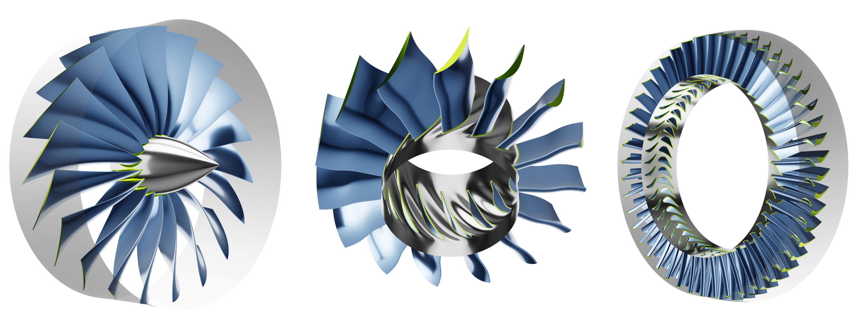
General Structure
Axial turbomachines predominantly consist of several adjacent stages, in which one stage comprises a rotor (rotating component) and a stator (stationary component). For compressors, the rotor sits upstream the stator, whereas for turbines this order is reversed.
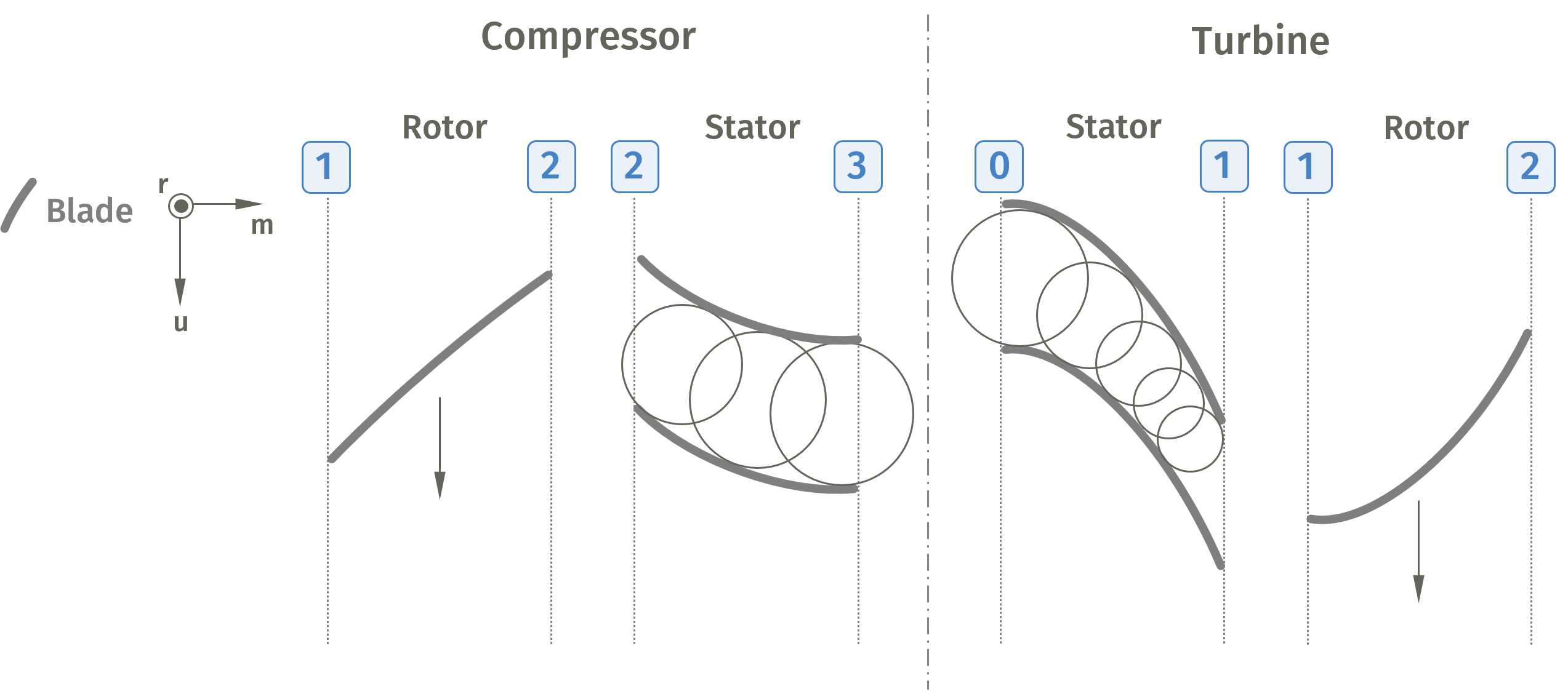
Two adjacent blades form a flow channel, which can be shaped as diffusers which are designed to decelerate the fluid in subsonic flow conditions or nozzles, designed to accelerate the fluid. Due to Bernoulli's principle, an increase or decrease in the fluids velocity is directly connected to a decrease or increase in static pressure. Hence in subsonic axial compressors the blade channel forms a diffuser to increase the fluids static pressure while in axial turbines (more specific: reaction turbines) the blade channel is often shaped as a nozzle. There are also cases in which the blade channel does not change the sectional area and just redirects the fluid without changing its velocity. These can be found e.g. in steam turbines and are known as impulse turbines. [7]
The three dimensional spaces in which the flow inside a turbomachine as well as the turbomachine component itself is usually described are the z-r--, the m-r-- or the m'-r--coordinate systems. Here, z is the main axis in axial direction, r is the radius of the machine, m is the meridional streamline and m' describes the normalized arc length of the meridional streamline. The angle relates to the rotation around the z-axis in the x-y-plane. [2]
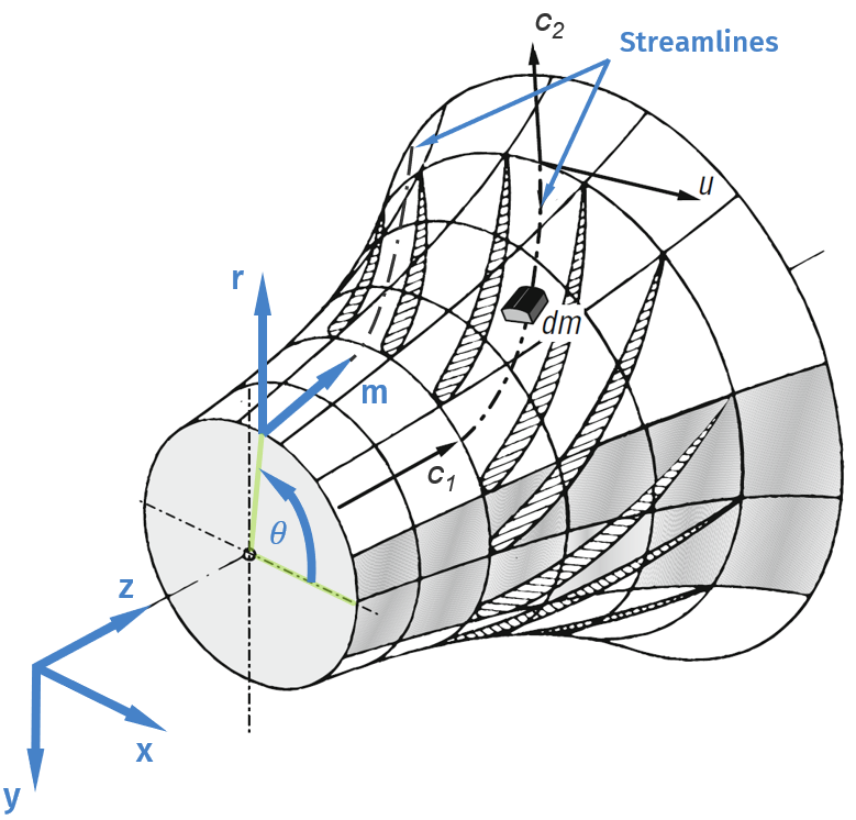 3D-coordinate systems [2]
Energy Transfer
The exchange of energy between the machine and the fluid is described by Euler's turbomachinery equation. This equation states that in order to increase or extract the fluids specific energy, the tangential component of the absolute velocity needs to change between inlet and outlet of the rotor. This change in velocity is done by redirecting the fluid and thus increasing the fluids angular momentum. Since the radius does not change notably between inlet and outlet of axial machine components, the work is primarily done by altering the value of .
 Euler's turbomachinery equation
In power delivering machines (axial compressors & fans) the specific work of the fluid is increased and thus is positive. The following figure shows a typical axial compressor design with its velocity triangles. Here, the rotor decelerates and deviates the relative velocity between inlet (index 1), and outlet (index 2), which causes the absolute velocity to develop a tangential component . Since the inflow of axial turbomachines is often purely axial to maximize the redirection and the circumferential velocity does not change between inlet and outlet, the fluids specific work is increased by Euler's equation. The stator's function is to extract the angular momentum and decrease the velocity from the fluid again in order to achieve similar inlet conditions for the subsequent stage. [7]
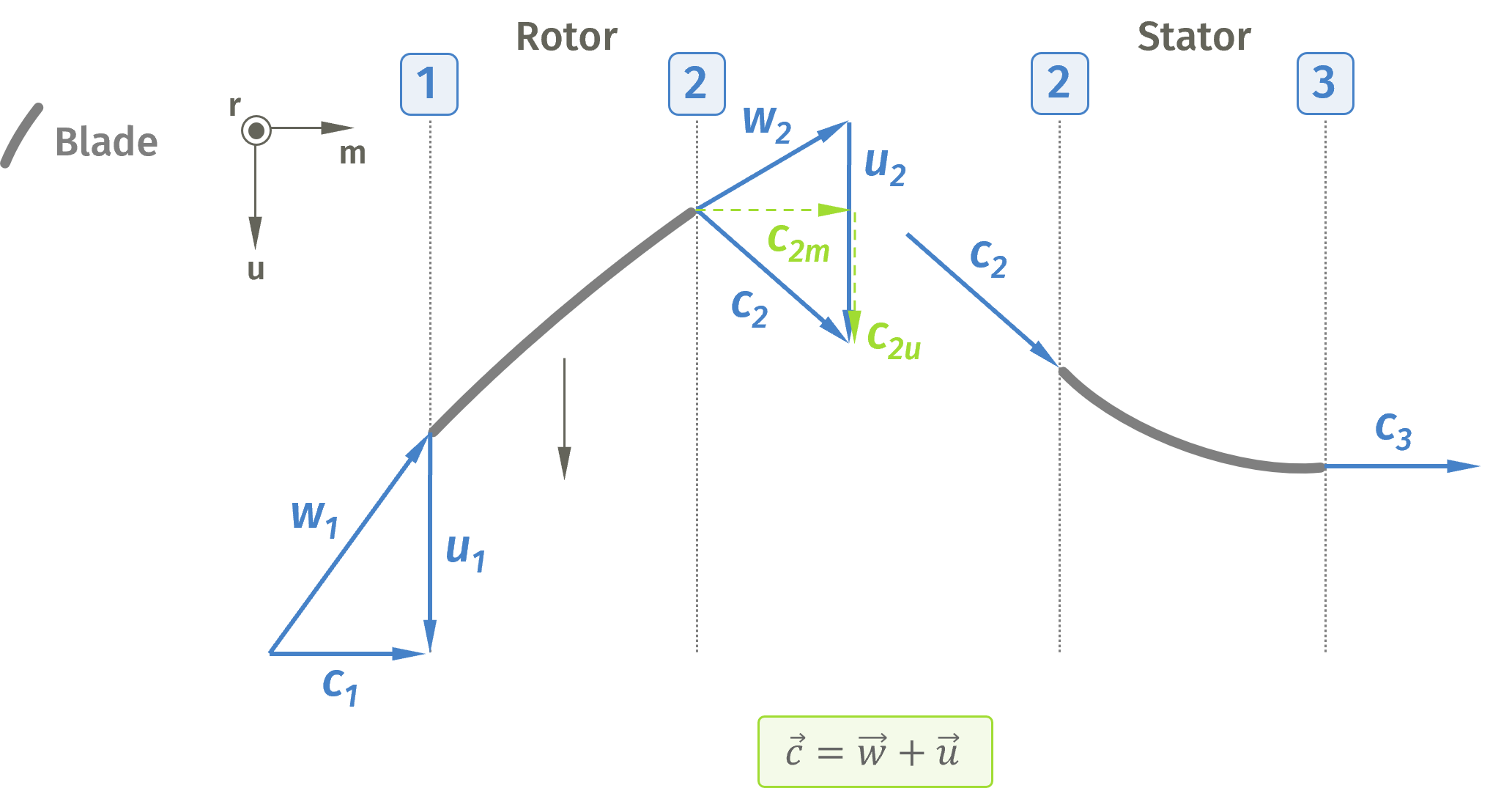 Axial compressor velocity triangles
For power receiving machines (axial turbines), the specific energy gets negative as these machines extract energy from the fluid and transfer it into mechanical energy. But in order to withdraw or minimize the tangential component of the absolute velocity inside the rotor, a stator first needs to introduce angular momentum by deviating the axial flow into tangential direction. Simultaneously, due to the nozzle shaped blade channel, the flow is accelerated to maximize the tangential component of the absolute velocity at the rotor's inlet . The rotor's task is to extract the tangential component of the absolute velocity by redirecting and accelerating the relative velocity between inlet and outlet. [2], [7]
Note, that in this nomenclature the indices of the rotor's inlet and outlet stayed the same independent of the machine being a power receiving or power delivering machine.
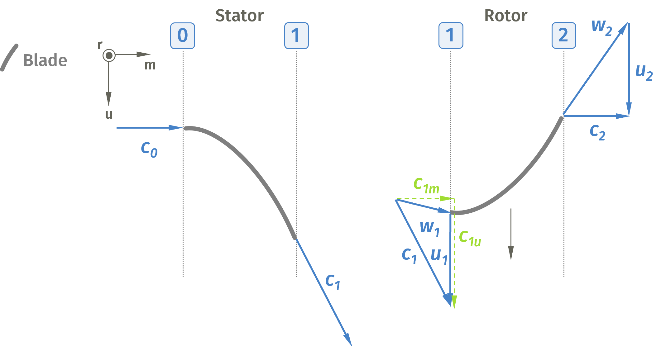 Axial turbine velocity triangles
Angles
Flow angles in turbomachines describe aerodynamic angles that the fluid flow follows. Due to secondary flow which is described as flow that is not following the primary flow direction and therefore can't be transferred into energy, the fluid is not able to follow the blade's contour perfectly. Hence, the work that is supposed to be converted by the airfoil's shape cannot be met. That's why secondary flow is also often titled aerodynamic losses. These losses have many sources, some of which are e.g. boundary layer losses, tip clearance losses or trailing edge losses, which in combination lead to complex three-dimensional vortex systems inside each bladed component. [5], [6] To account for secondary flow, airfoils are overly cambered, leading to a discrepancy between flow and blade angles. The following image visualizes the difference between flow angles (, ) and blade angles (, ). Following angles are important in the design process of turbomachines:
- inlet flow angle of the relative velocity
- outlet flow angle of the relative velocity
- inlet blade angle
- outlet blade angle
- incidence angle
- deviation angle
- inlet flow angle of the absolute velocity
- stagger angle [2], [3]
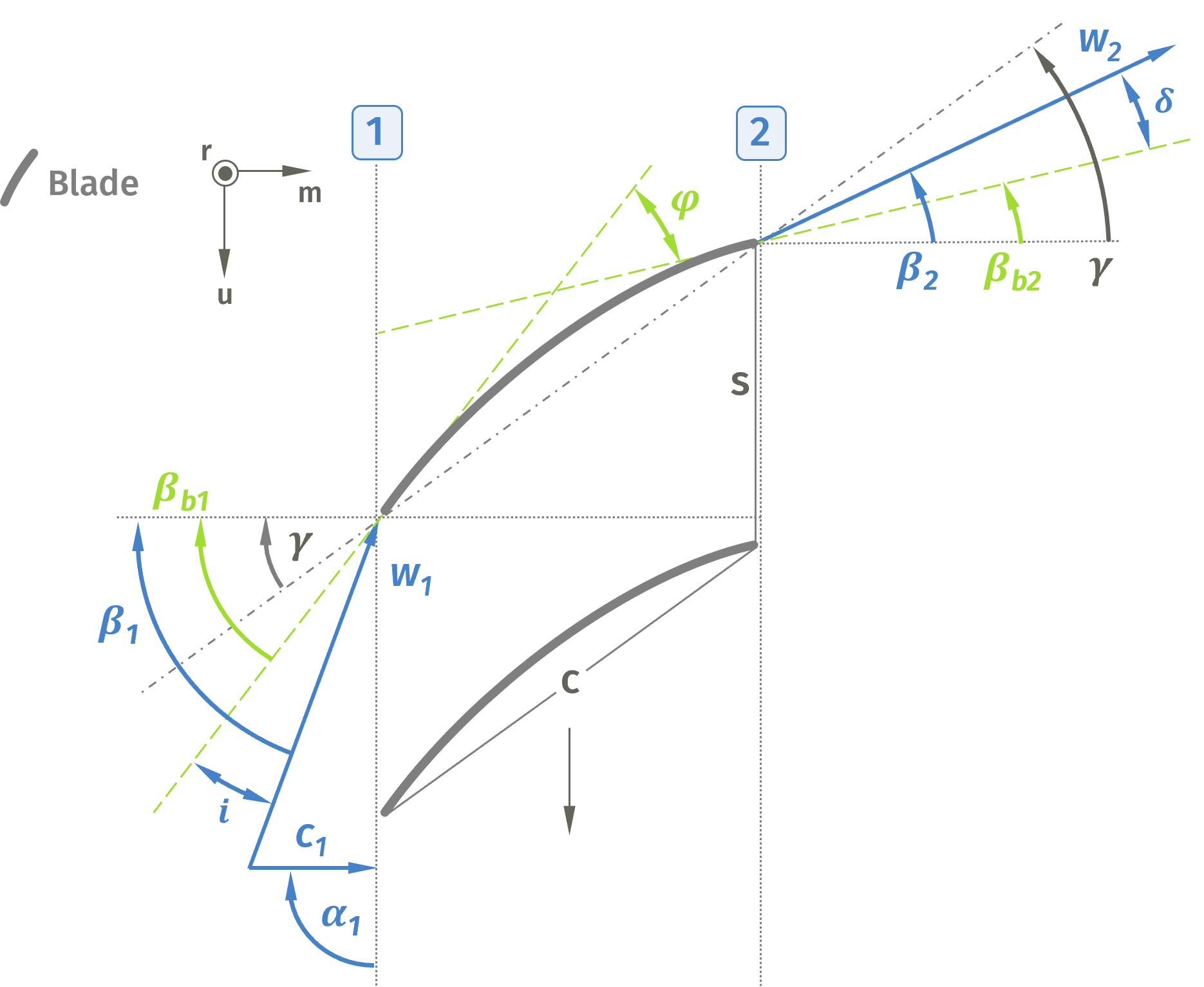 Flow and blade angles for axial blades
Blade Loading
An important dimensionless parameter in the design of axial turbomachines is the blade solidity . This parameter sets the spacing between two blades into relation with their chord length . For a given power transfer, there is a range in which a certain blade solidity causes a minimum in total pressure loss and therefore leads to maximum efficiency of the machine. A blade solidity which is too high would result in too much friction losses due to the high number of blades which lead to larger surface areas in total. On the other hand, if the blade solidity is set too low, flow separation could emerge due to high blade loading. [5]
 Blade solidity equation
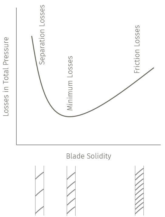
Blade Solidity vs. losses in total pressure [7]
This is especially relevant in axial compressors, since the positive pressure gradient leads to an early laminar-turbulent transition along the suction side of the blade and enhances the risk of flow separation. Flow separation must be avoided, as it can cause blockage within the blade passage, reduce work transfer due to decreased flow deflection, and, in severe cases, trigger global separation leading to compressor stall. In order to avoid flow separation in axial compressors, Lieblein introduced the diffusion factor (DF), which limits the maximum diffusion along the suction side of a blade, also taking the blade solidity into consideration: [2]
 Diffusion factor equation