Radial Turbomachine Workflow in CAESES
Without any doubt, the blades are the central component of any turbomachine. They transfer energy between a rotating shaft and a fluid, and depending on whether the turbomachine in question is a turbine, a compressor, a pump, a fan, or a propeller, they either extract energy from or impart energy to a continuously moving stream of fluid. Depending on the application, blade designs come in a large variety of shapes, which are typically defined by their cross-section and how it changes in spanwise direction. These properties largely determine the turbomachinery’s performance and can encompass rather large design spaces, which can only reasonably be inspected with automated workflows.
CAESES offers capabilities for modeling and shape optimization of any type of blade, e.g. for pumps, fans, turbochargers, aero engines and propellers.
For an overview of turbomachinery types and design fundamentals, see:
- Turbomachine Types — axial, radial, and diagonal machines: fans, compressors, pumps, and turbines
- Axial Turbomachines — geometry and aerodynamic fundamentals for axial-flow machines
- Axial Turbomachine Workflow — step-by-step axial fan and compressor blade design
- Volute Design — scroll housing geometry for pumps and turbochargers
Related tutorials:
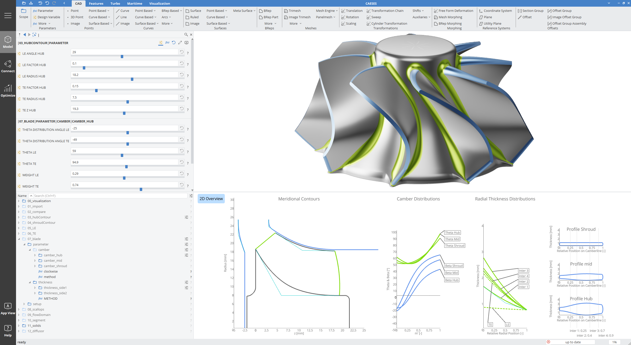
The turbomachine workflow provides both an extensive selection of dedicated design components, and a step-by-step guide through the geometrical modeling process of a fully-parametric turbomachine design. After setting the machine (compressor, turbine, pump or fan) and the flow type (centrifugal/radial or axial), the workflow streamlines the creation of every necessary geometry object and parameter, to help you create a powerful and flexible parametric model in less than half an hour.
The wizard-like approach supports beginners and advanced turbomachine designers in selecting and using machine type dependent features available within the add-on TurboThis functionality requires the Turbo add-on to be enabled., keeping the project structure clean and organized, and making the modeling process faster.
Step 1 | Choose the Machine Type
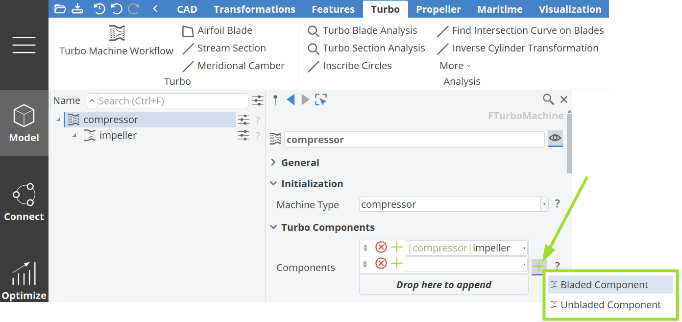
To start your parametric turbo machine design create the TurboMachine object by clicking on the Model workspace > Turbo tab > Turbo > Turbo Machine workflow.
In the drop down menu for the Machine Type choose the machine type you would like to model. The machine type will be used internally to suggest specific objects, features, and commands in the design workflow.

Step 2 | Add a Bladed or Unbladed Component
Add a bladed or unbladed component to your machine design.
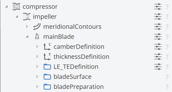
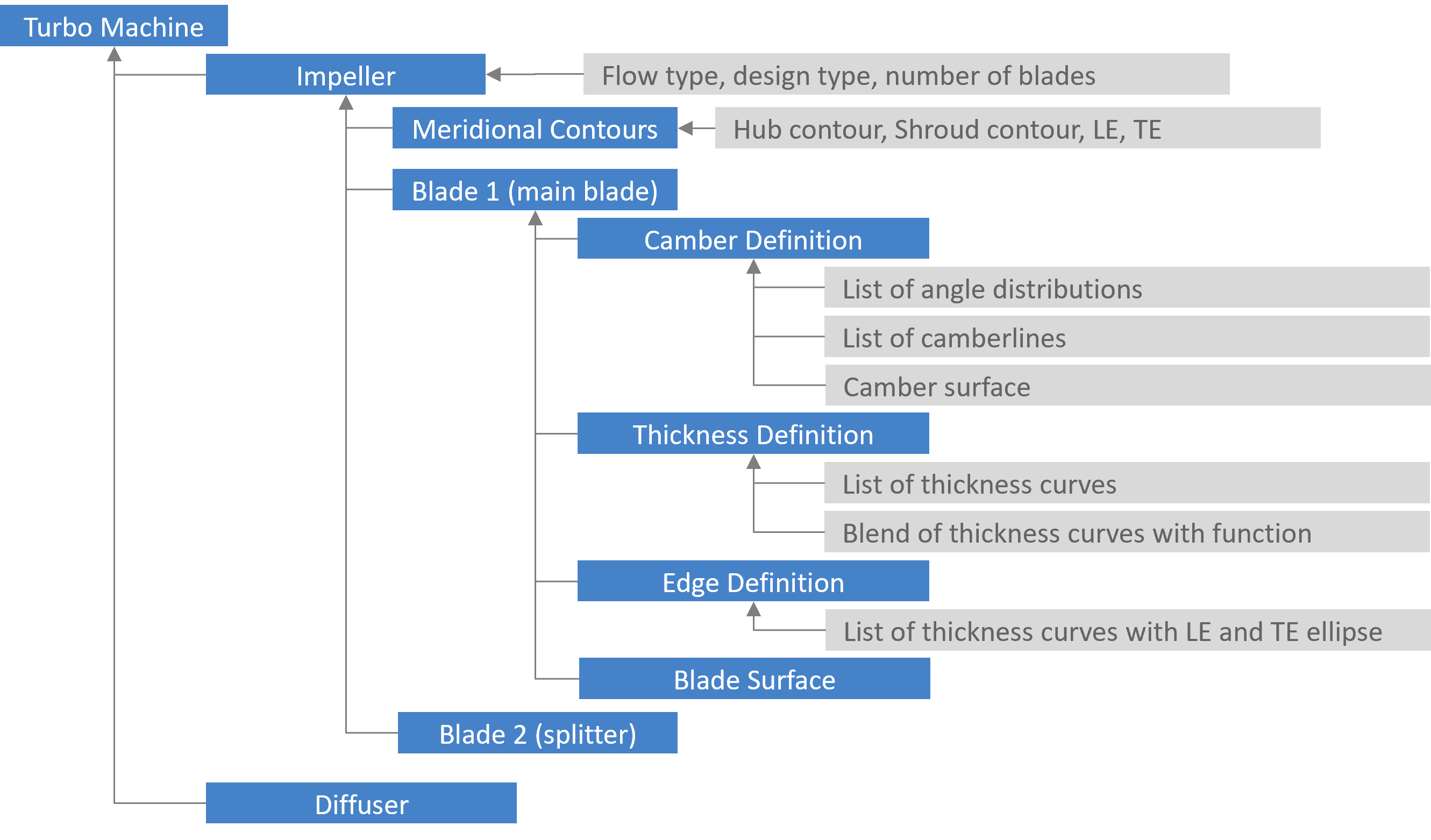
The BladedComponent can be used to create a stage or row of the machine with one or more blades. It includes the
- Meridional Contours and
- a list of Blades.
Flow Type
Set the flow type and choose between a centrifugal/radial setup or an axial flow.
The flow type will be used to initialize components like the FMeridionalContours object in the design workflow.
If you want to design mixed flow machines you need to decide if the machine is more "centrifugal / radial" or "axial" and then adjust the suggested parametrizations to your needs, accordingly.
Design Type
With the design type the user can decide if the blade should be modeled based on a mean camber surface or directly with airfoils / hydrofoils.
With the camber approach the blade is modeled with a camber surface and thickness curves, which are mapped on the camber surface. The object FBladeCamber will help the user to create the angle distributions and FStreamSections to form the camber surface.
With the airfoil approach the user will model the blade profile curve in the 2D x,y - plane with a feature definition. Based on this definition the blade is created with the FAirfoilBlade, which will transform the 2D profile into 3D space.
Number of Blades
Set the number of blades for your turbomachine or create a design variable for it, to easily change it. One main blade and one splitter blade are considered as one blade unit. If you set the number of blades to 5 your model includes 5 main blades and 5 splitter blades (in between the main blades).
Step 3 | Define the Meridional Contours
Define the 2D channel curves of the turbo machine, which are called the "meridional contours". The curves need to be given in the x,z-plane, where the x-coordinate corresponds to the radius, the z-coordinate corresponds to the axial direction (z = rotation axis).
In general, the direction of the flow defines the location of the meridional curves, therefore following conventions are used:
-
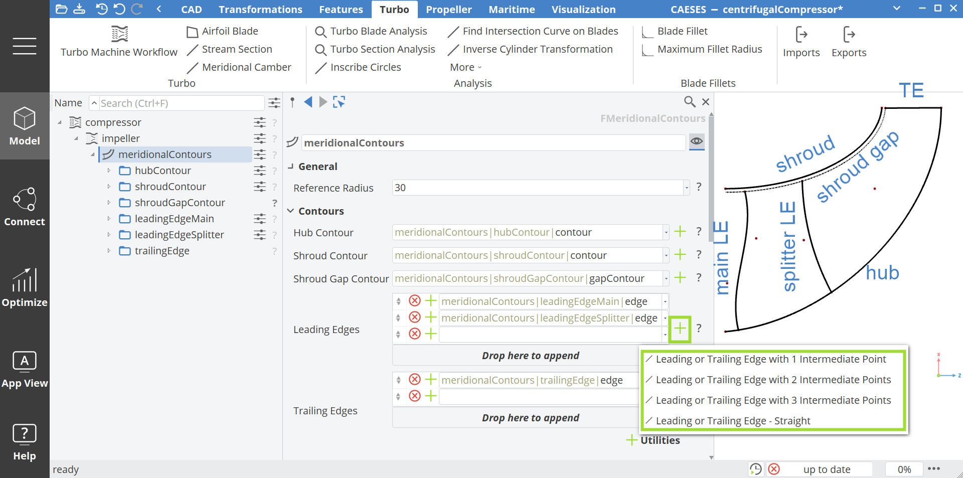
For centrifugal pumps and compressors, the hub and shroud curves start in the negative z position and develop into the positive z direction. The x-coordinates (radius values) of the endpoints are larger than the start points.
-
For radial turbines, the hub and shroud curves start in the positive z position (where the hub usually starts at z=0) and develop into the positive z direction. The x-coordinates (radius values) of the endpoints are smaller than the start points.
-
For axial machines, the hub and shroud curves start at z=0 and develop into positive z-direction.
You can either define your own meridional curves or add pre-defined contours by clicking on the + to the right of each input line. A list of available pre-configured curve types is shown.
Step 4 | Create the Blade
Various blades can be added to the impeller (Bladed Component) setup, that use the same meridional contour definitions.
Once you added a blade in the impeller, the leading and trailing edge information will be taken automatically from the meridionalContours.
If the mean camber based creation option is chosen, you can add a camber definition by clicking on the + icon next to the Blade Camber field.
Blade Camber Definition for Radial Machines
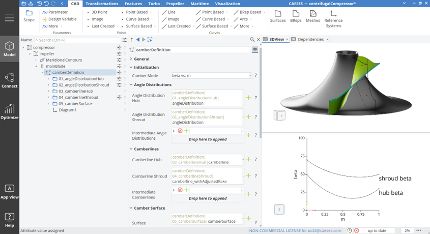
In the Blade Camber object the angle distributions for hub, shroud, and intermediate span positions can be created.
| 1. Angle Distribution | 2. Streamline Creation | 3. Camber Surface Creation |
|---|---|---|
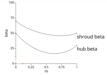 | 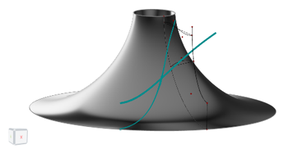 |  |
Based on angle distributions and the Meridional Contours (defined in the previous step) the camberlines for the hub, shroud, and (optionally) intermediate spans can be created.
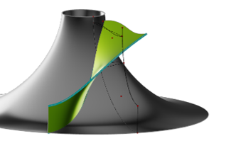
In the last step the mean camber surface can be created by choosing a creation method from the different stacking options:
- Camber Surface via Lofting
- Camber Surface via Radial Stacking
- Camber Surface via Equally Spaced Stacking
- Camber Surface via Linear Stacking
Thickness Definition
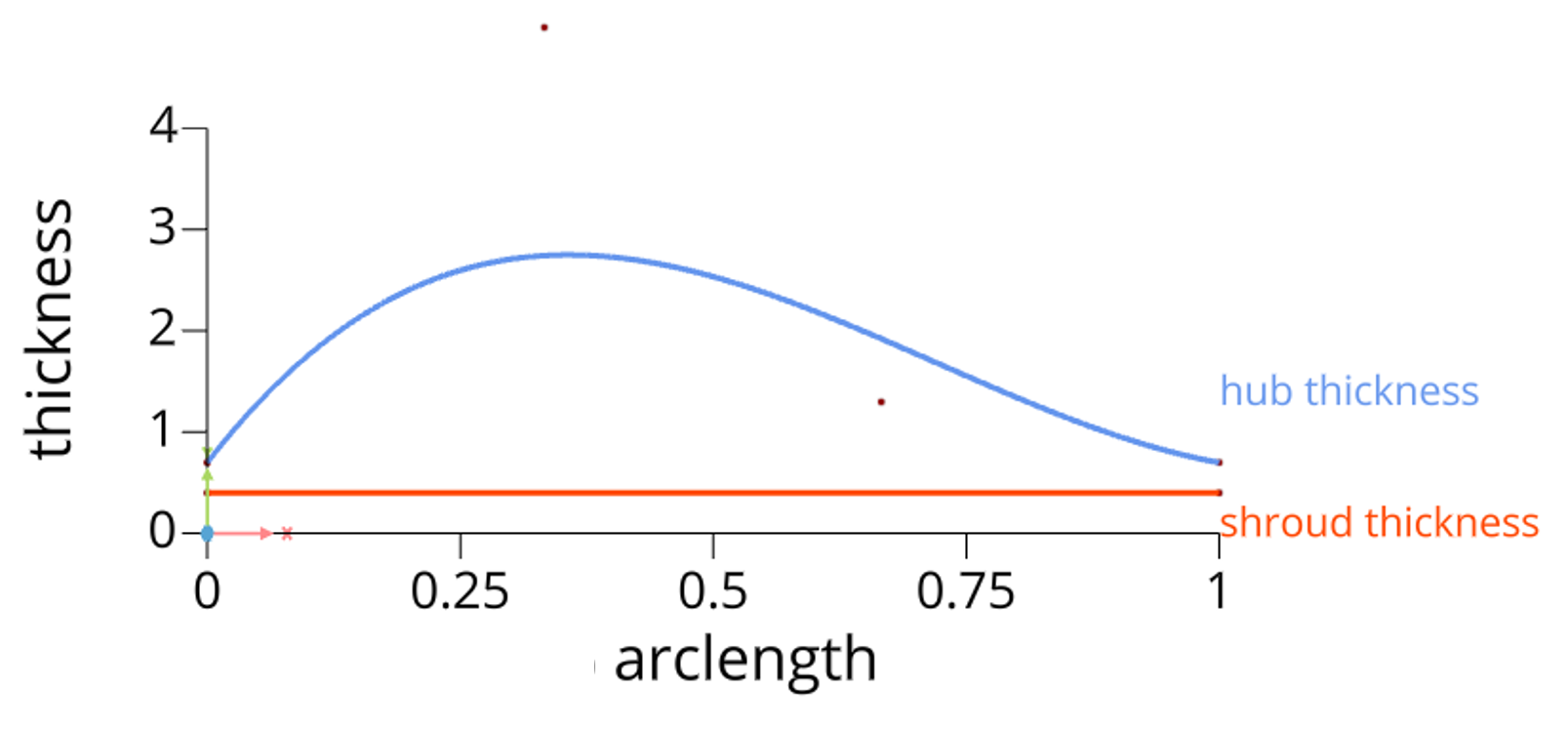
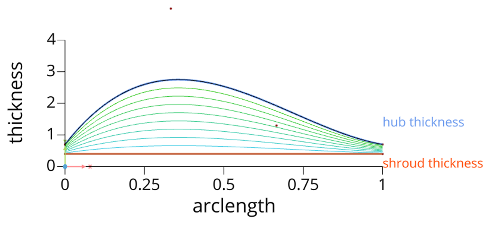
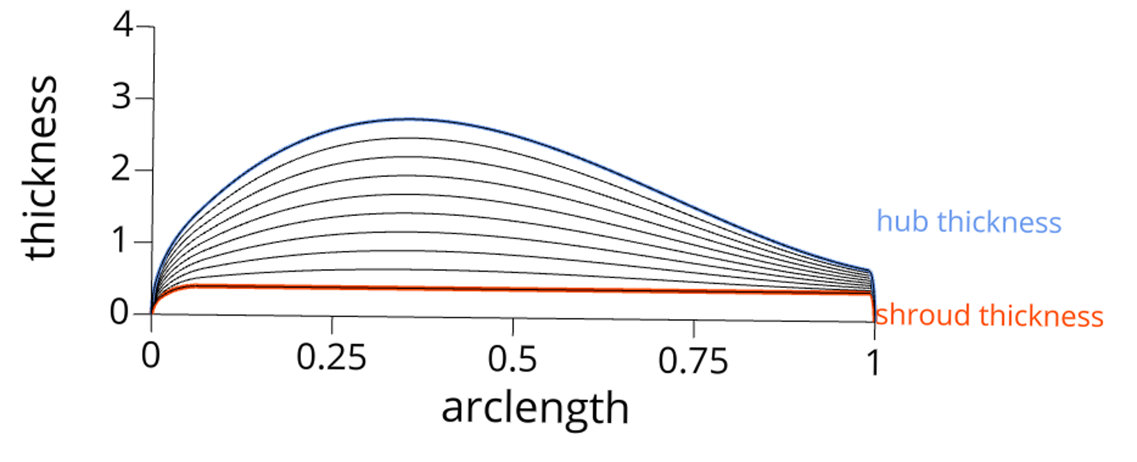
A thickness definition for the thickness at hub and at shroud are needed and defined as a 2D function. These functions will be used to create the intermediate thickness distributions for spanwise intermediate positions between hub and shroud based on a blend function.
Optionally the user can set the list of thickness curves manually.
Edge Definition
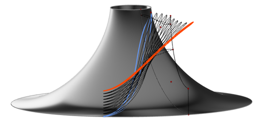
The Edge Definition provides how the leading and trailing edge shape should be created. To achieve a closed edge the previously defined thickness curves need to run to a thickness of zero to close the leading and trailing edge of the blade. Therefore, an ellipse is added at the start and end of each 2D thickness curve. The ellipse factor can be set as a constant value or described by a function to control the elliptical shape from hub to shroud.
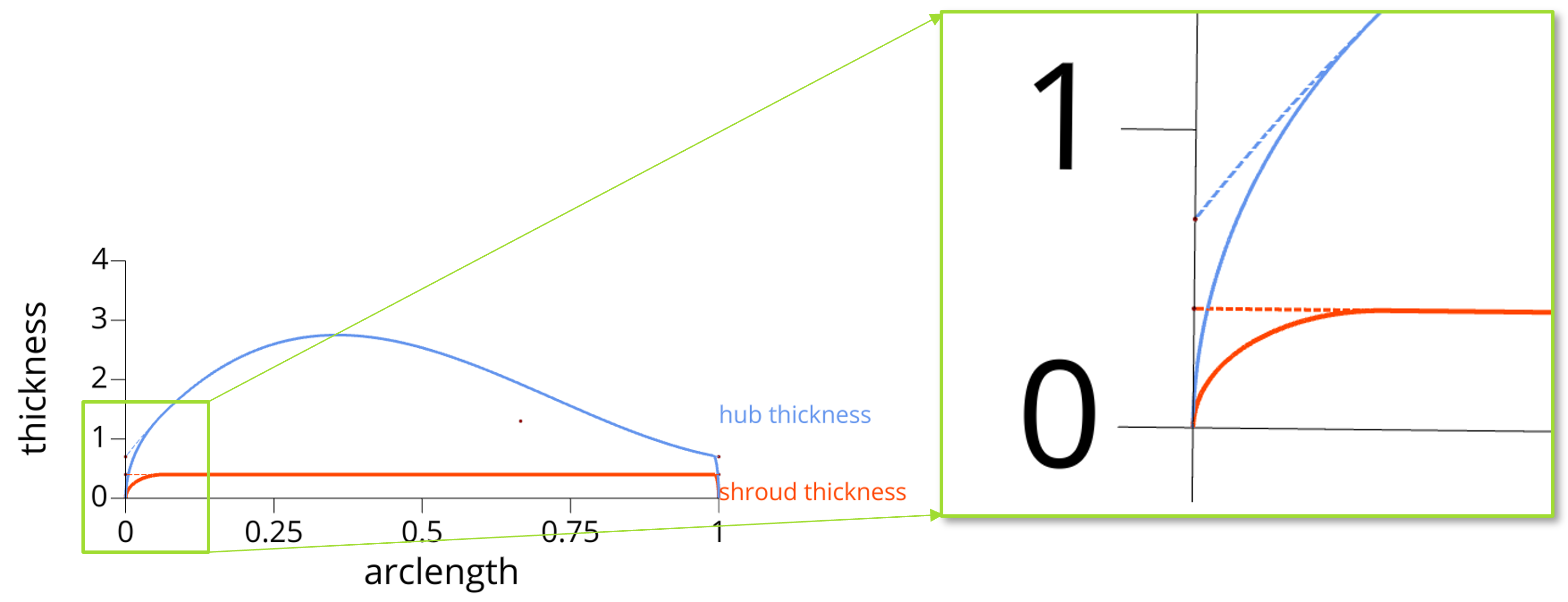
The ellipse is added to every (intermediate) thickness curve from hub to shroud.
Blade Surface
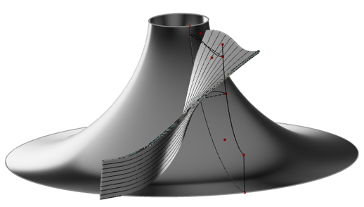
In the final step the blade surface is created as a lofted surface.
Additional Functionality
The Add-on Turbo offers more powerful functionality in addition to the turbomachine workflow.
Advanced Blade Fillets
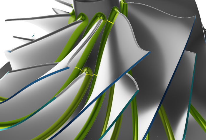
A great amount of development time has been spent on blade fillet creation. The fillet object allows you to easily create constant or variable radius fillets and offers the option to include a boundary edge optimization to let the fillet run up to any specified boundary curve.
Calculate the Maximum Fillet Radius
A new feature calculates the maximum fillet radius between two blades, which guarantees a 100% robust and smooth fillet creation.
Use the maximum feasible fillet radius or set your own value to create a robust fillet with a constant radius around the blade geometry.
Variable Blade Fillet with Radius Distribution
Define flexible radius functions to design the blade fillet with variable radius from the leading edge to the trailing edge for both sides of the blade.
Variable Blade Fillet with Boundary Optimization
Optimize the fillet radius to run up to a pre-defined boundary to avoid overlap.
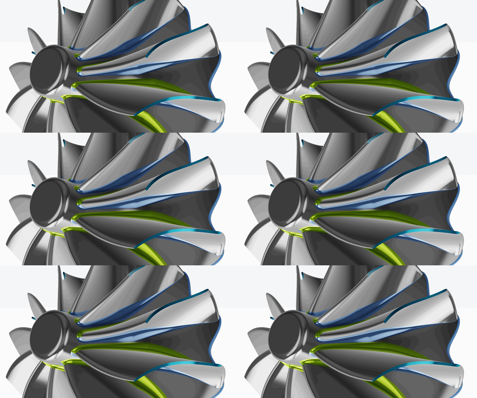
Analysis Tools for Blades
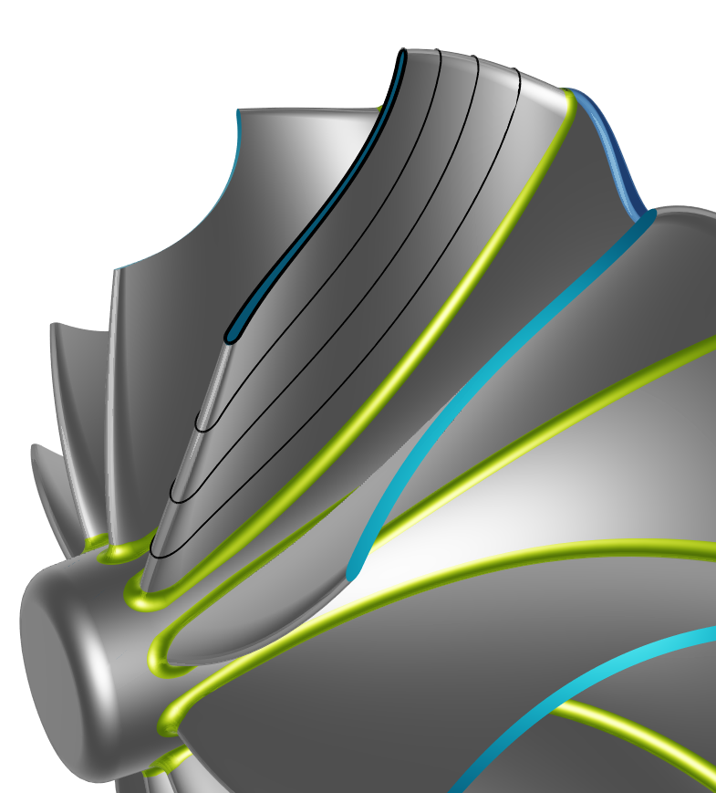
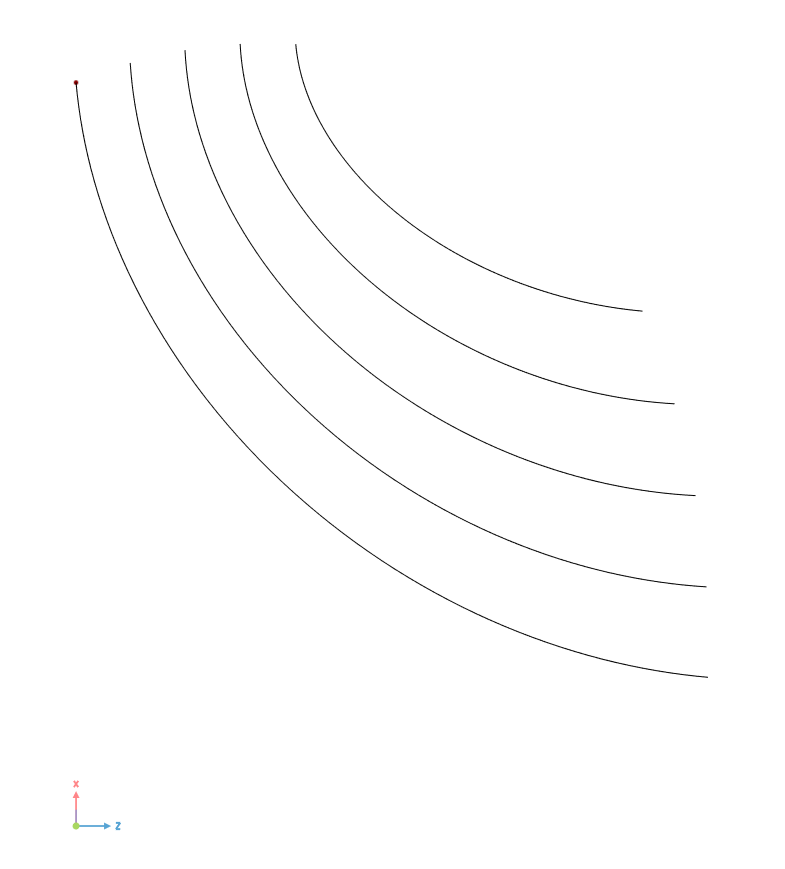
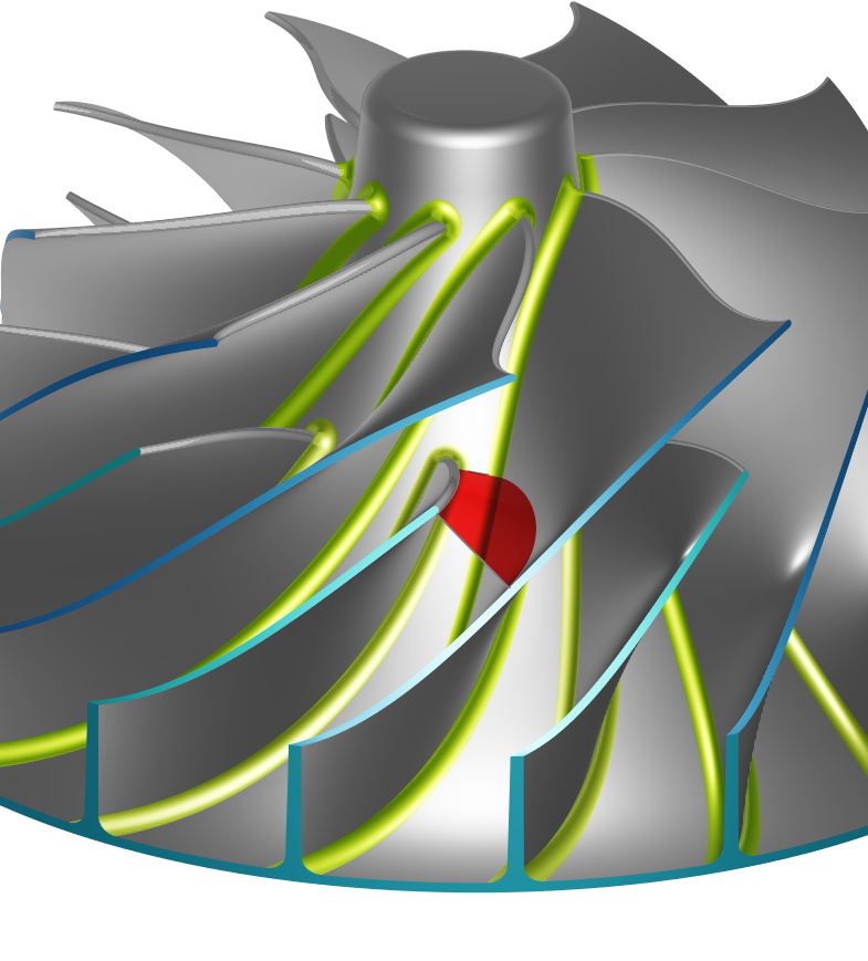
Quickly analyze any imported or existing blade geometry with the newly implemented analysis tools. You can now easily extract the mean camber surface, determine the blade and wrap angle (beta/theta) distributions, calculate the throat area between blades, or transform the 3D edges to the meridional plane. This toolkit allows you to quickly build a fully-parametric model from imported geometries.
| Analyze 3D Section | Derive Meridional Contour | Throat Surface |
|---|---|---|
 |  |  |
Check the tutorial video on the analysis tools for imported blades.
Turbomachinery Samples
Take a look at the sample models for
- a centrifugal pump,
- a radial turbine with variable radius fillets and scallops,
- a centrifugal compressor including splitter blades,
Webinar on Turbomachinery Design with CAESES
Watch the release webinar and find out more about the new turbomachinery functionality, released in CAESES 5.2, that simplifies and streamlines your work, to facilitate the parametric design of turbomachines.