Hard Chine Boat (from Scratch)
In this tutorial, a parametric hard chine boat will be created from start to finish. This project is useful for understanding the applicability of different surface generation methods in CAESES for hull design.
To quickly set up a parametric hard chine boat in a couple of minutes, see the hard chine workflow tutorial.
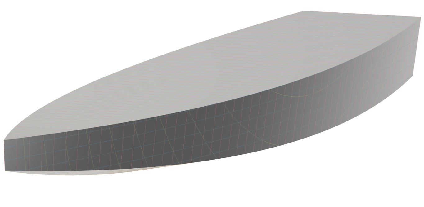
It encompasses four distinct surface generation methods:
Introduction
As a starting point, a project file is provided which already contains a basic scope structure, as well as all the parameters and design variables that will be used when setting up the model. Naturally, the given settings represent only one possible configuration and may be changed and adjusted by the user to their liking.
Get started with the following project file:
Get StartedBased on the given normalized 2D functions (see figure below), geometry curves such as keel, knuckle, deck and transom curves will be created. These curves will guide the design of the hard chine surfaces, which serve as the basis for the final watertight BRep.
Functions
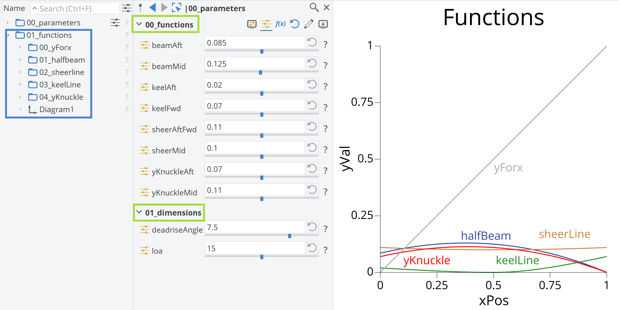
In the figure below, the 2D functions of the boat hull are shown. The halfBeam, sheerLine, keelLine and yKnuckle are typical elements in hull design. Mostly, Interpolation Curves were used for generating these functions, allowing exact control over the curves. Adjusting the design variables and referencing their names allows the user to understand their effects on the curves. By clicking the design variables icon inside the green rectangle, you can view the variables used for the functions and adjust the sliders. The yForx is a generic curve and indicates the parameterization of the 3D curves that will follow, preferably set as the function y=x, as shown.
Dimensions
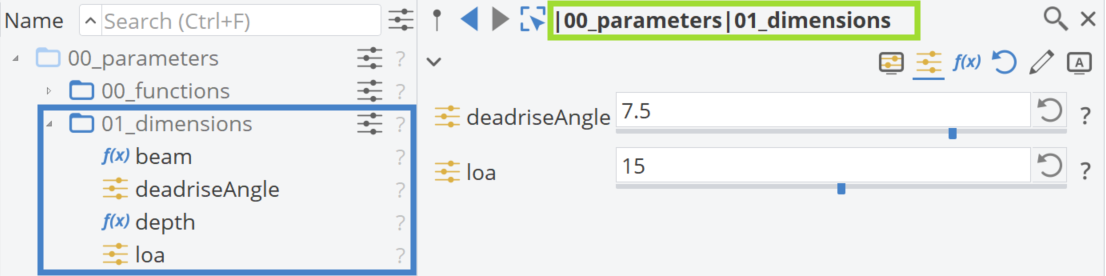
Create a new scope named |01_dimensions| under |00_parameters|. Two new design variables are introduced: deadriseAngle with a range from 0 to 10 degrees and loa (length overall) with a range from 5 to 25 meters. Parameters for beam and depth are calculated as follows:
beam = loa * |00_parameters|00_functions|beamMid * 2
depth = loa * |00_parameters|00_functions|sheerMid
Geometry Curves
The next step is to generate the 3D curves of the hull.
Deck and Keel Curves
- Create a new scope in the object tree and name it "02_curves"
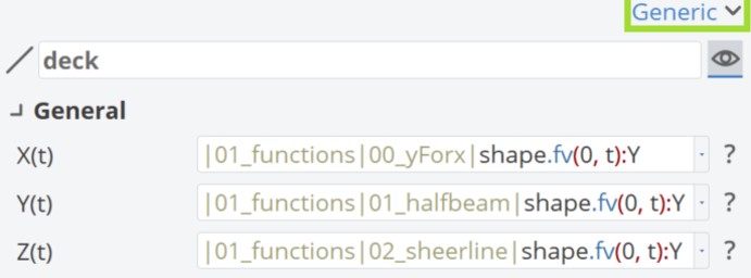
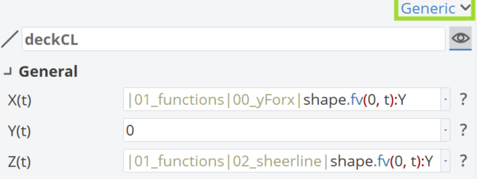
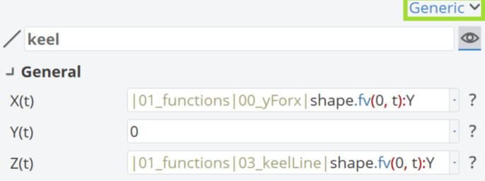
- Create a Generic Curve for the deck curves and the keel by choosing Model > CAD> Curves > More > Generic.
The Generic Curves combine the information from the 2D curves to find the proper 3D curve, opposite of the projection. Both curves use the yForx function for X(t) and the corresponding values from the 2D functions for Y(t) and Z(t).
Knuckle Curve
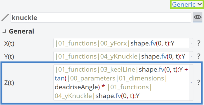
For the knuckle curve, the same logic as the generic curve is used, with the term tan(|00_parameters|01_dimensions|deadriseAngle) * |01_functions|04_yKnuckle|shape.fv(0, t) added, as seen in the figure below.
Straight Lines
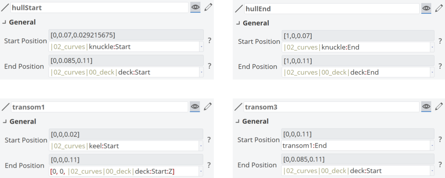
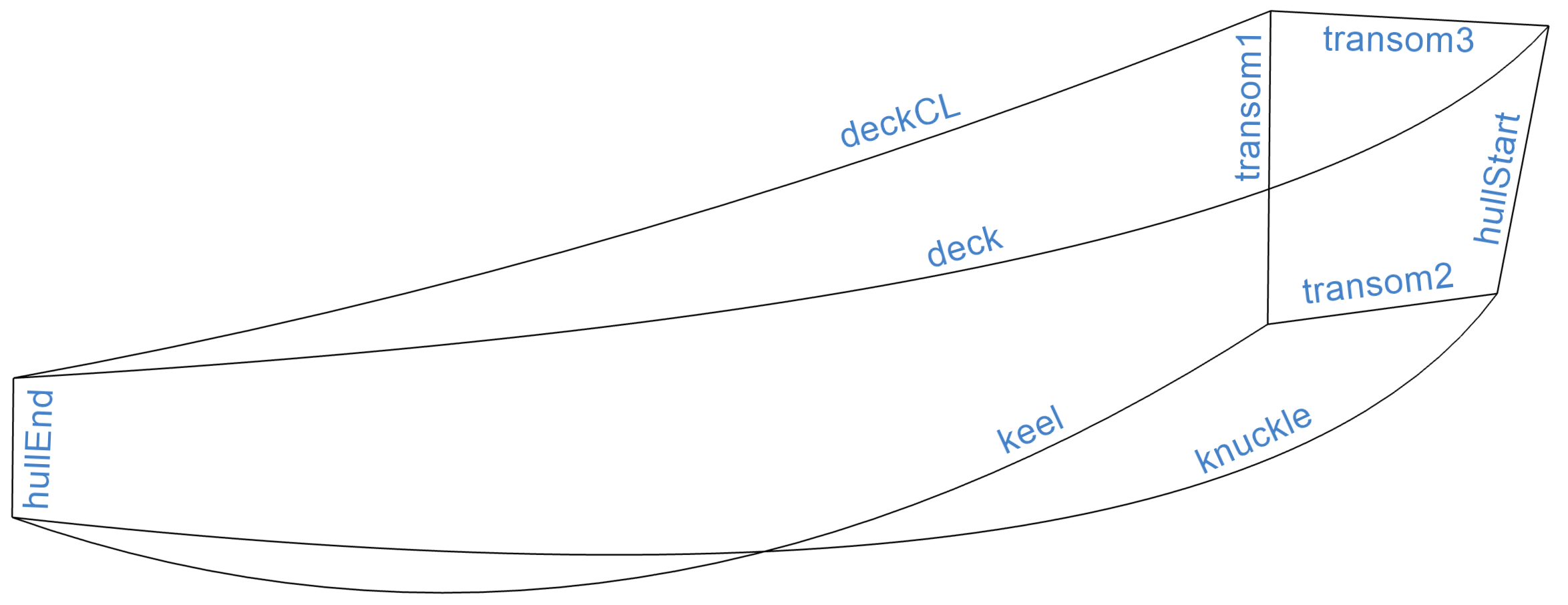
Also, Lines were used for the 3D curves, as seen below, for the hullStart and hullEnd and for auxiliary transom curves (transom1 and transom3).
In the figure below, all the geometry curves are shown, including the transom2 curve, which is generated from an Image curve of the bottom surface's edge. This will be described in the next section.
Hull Surfaces
Curve Based Surfaces
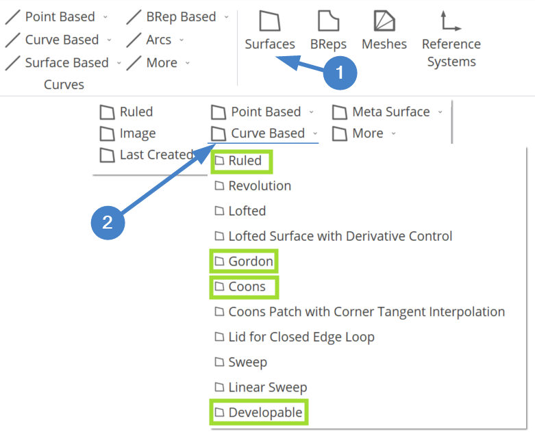
Now we can move on to the surface generation by creating a new scope, |03_surfaces|. As discussed above, four different methods will be used for surface generation and here is a figure of how we can generate those inside CAESES (Model > Surfaces > Curve Based >).
Side - Gordon Surface
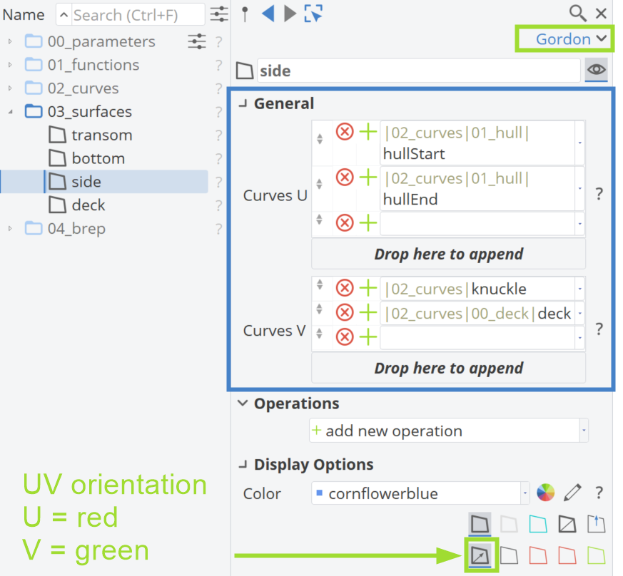
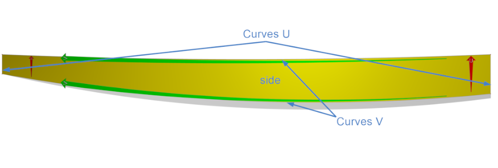
Starting from the side of the hull, a Gordon surface is used, which needs a list of curves in the u and v parametric directions. The user can enable the view of the UV orientation by checking the green highlighted button.
Bottom - Developable Surface
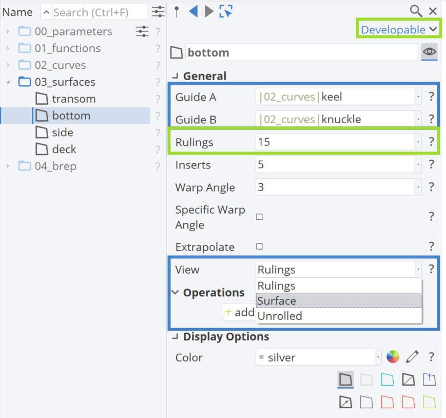
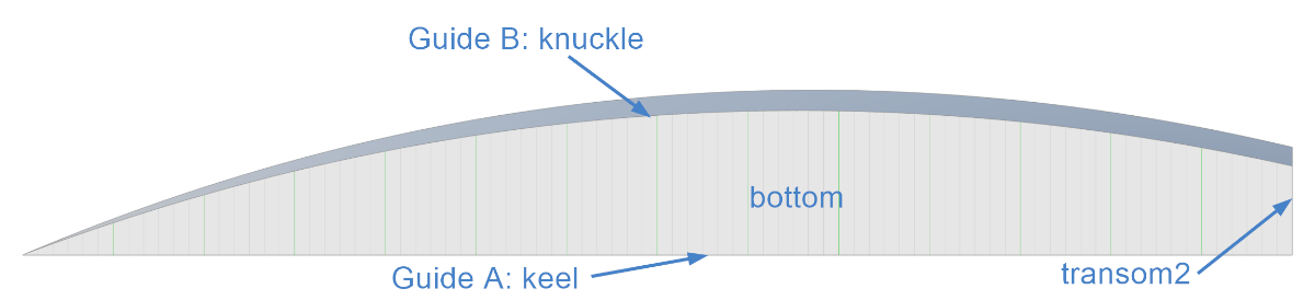
Continuing to the bottom of the hull, we will use a Developable surface, which needs two guide curves (A and B) to be generated. The user can adjust the number of Rulings as preferred and then change to the Surface View. Rulings are straight lines that connect corresponding points on the two guide curves, defining the surface. From this surface, the transom2 curve is generated from an Image curve, stored in the |02_curves| scope and will be used for the transom generation.
Transom - Coons Patch
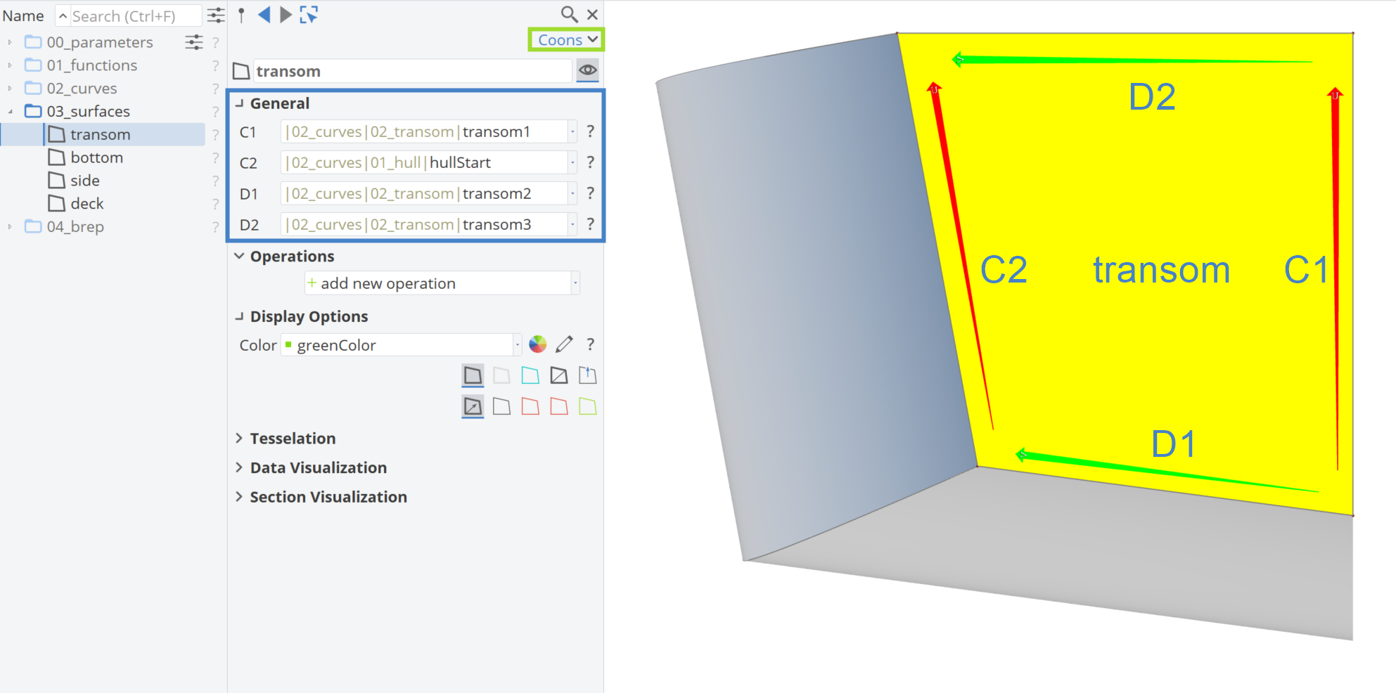
The final surface is the transom, which uses a Coons patch. This surface creates a 4-sided NURBS patch, requiring four curves (C1, C2, D1, D2).
Deck - Ruled Surface
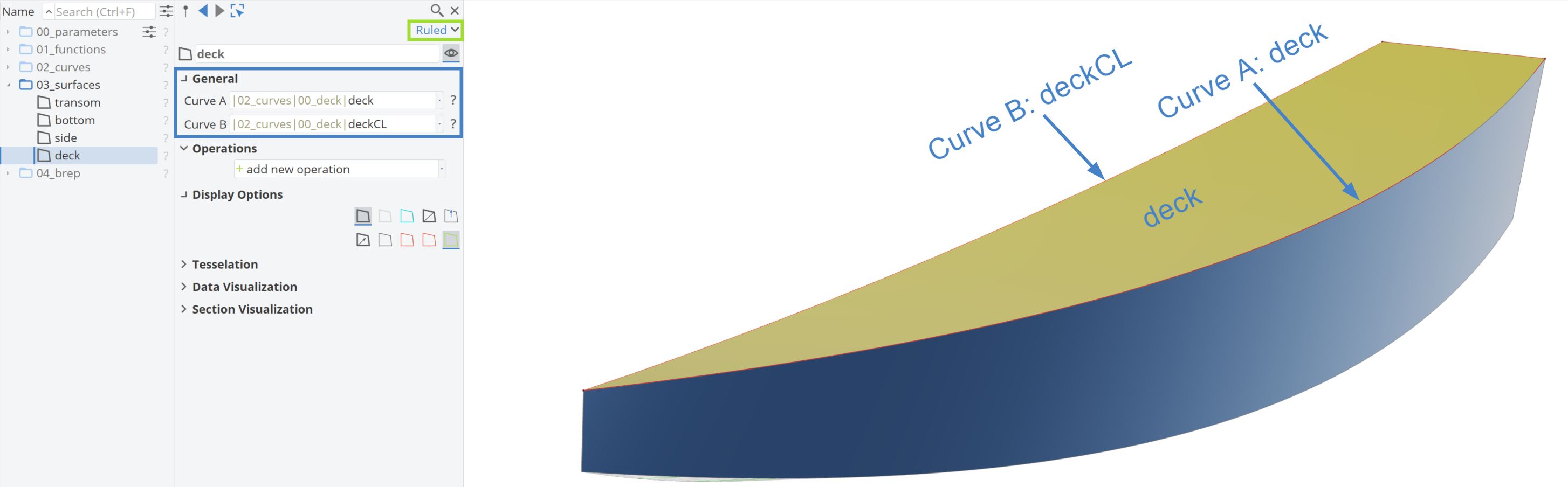
To generate a closed BRep, we also need to design the deck surface. For the deck surface generation, a ruled surface is used, requiring two input curves from the scope |02_curves|. One curve represents the deck, and the other is the deckCL (deck at the center line).
Design Variables Animations
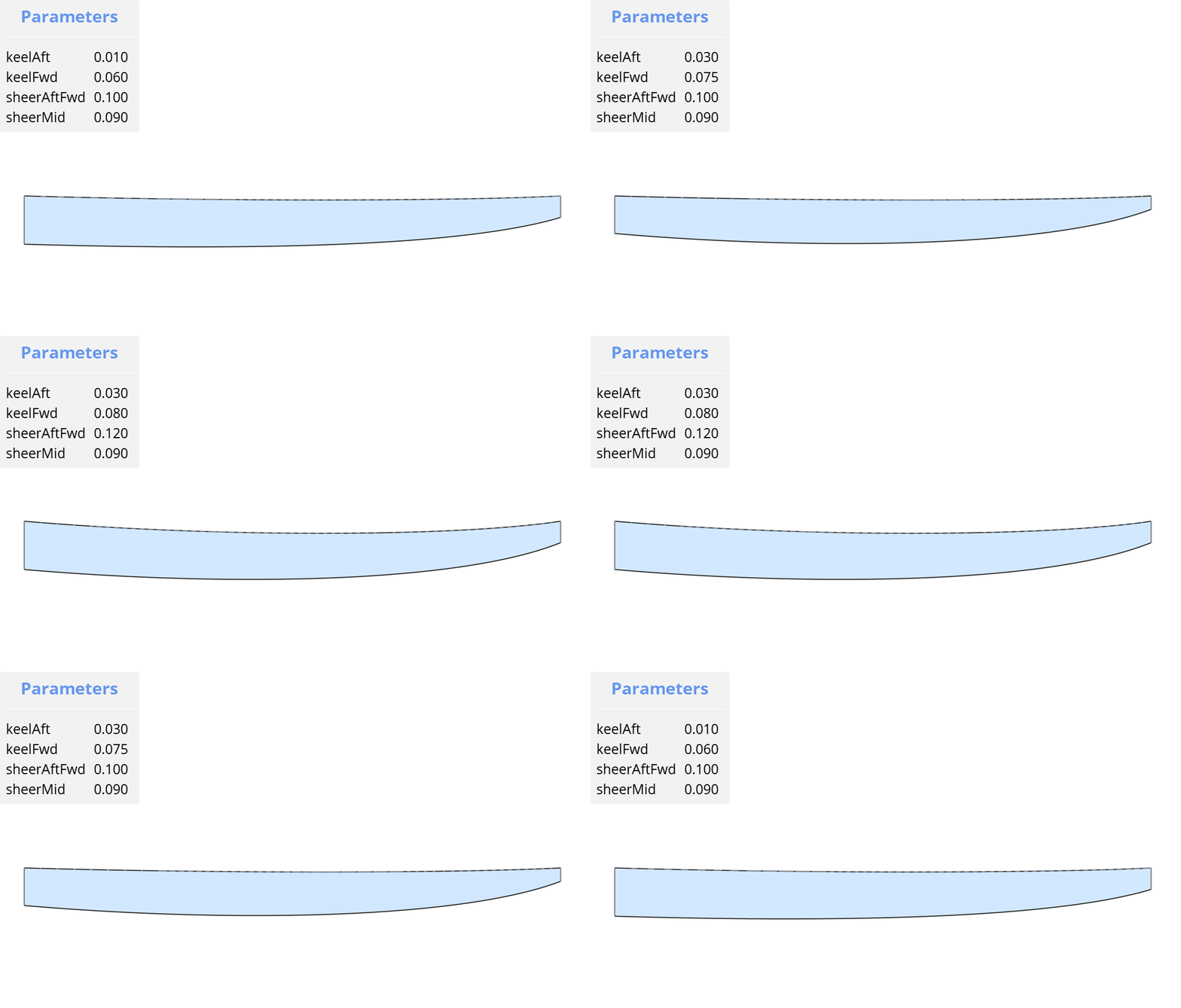
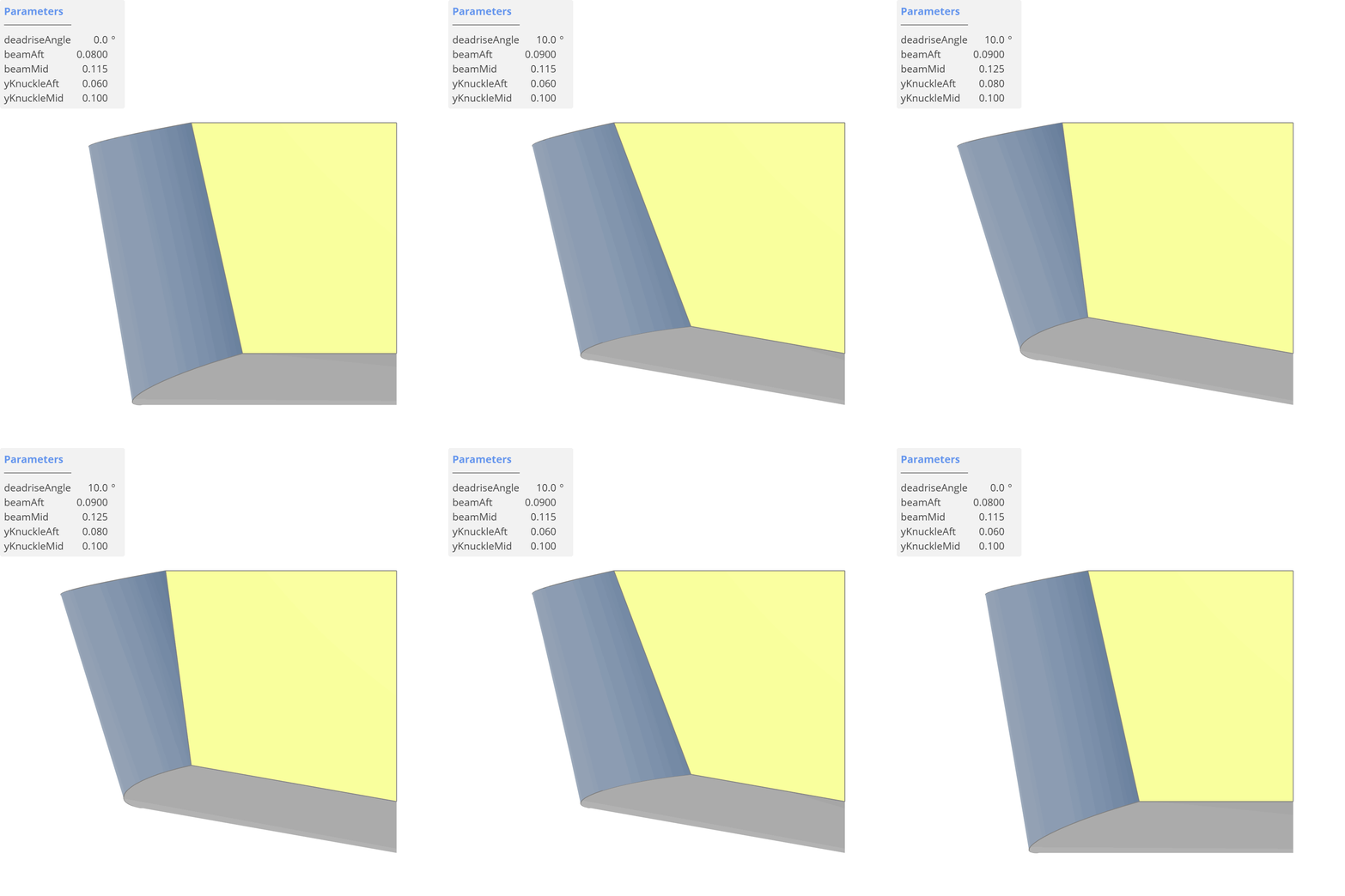
Additionally, there are two animations visualizing how the surfaces change by varying the design variables of this parametric model, one showing the effects on the geometric objects from the side view and the other from the back view. The values of the design variables are displayed in the upper left corner.
Solid Creation
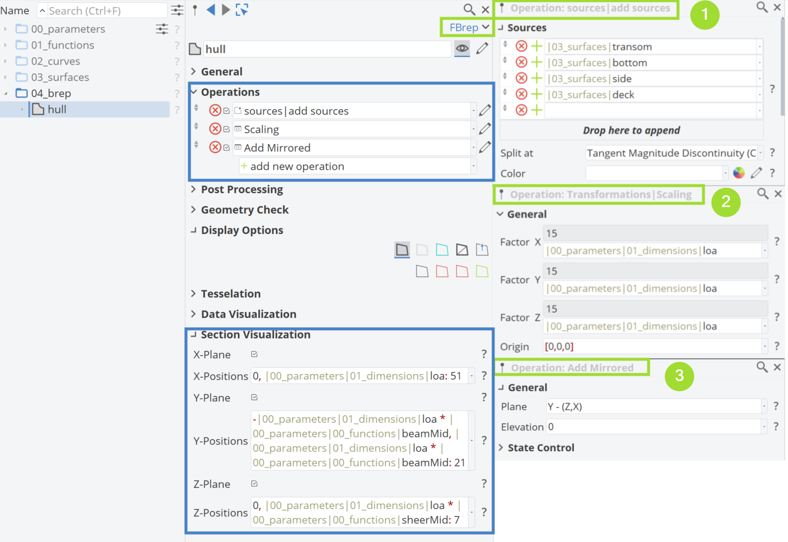
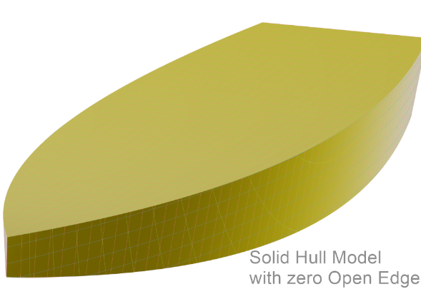
With the hull surfaces generated, the model needs to be closed and solid to be used later for CFD if desired. Thus, we create a new scope named |04_brep|. A new BRep is created named hull and three operations are applied to this object.
- Add Sources: The hull surfaces from the scope |03_surfaces| are added here.
- Transformations|Scaling: The model is scaled based on the parameter |00_parameters|01_dimensions|loa in the ΧΥΖ directions. If no scaling is assigned, the length of the hull will be one.
- Patterns|Add Mirrored: The hull is mirrored to have the full model with zero open edges, with plane Y functioning as the mirror plane.
Additionally, section visualization is applied with 51 sections, 21 buttocks and 7 waterlines for the full model.
CAESES Project File
If you want to take a look at the finalized parametric model you can find the resulting CAESES project file hardChine.cdb here: