Component-Based Ship Workflow
The Component-Based Ship mirrors the typical naval architecture workflow, where:
- Hull Parameters are defined as a foundation for the design.
- The ship geometry is modeled by dividing it into distinct regions:
- Optional hull-form features, such as a skeg and/or a bulb, can be added to further shape and refine the main hull geometry.
- Optional appendages, such as a rudder and/or propeller, can be included as separate components to complete the overall ship configuration. 5.4.0This functionality requires CAESES version 5.4.0 or later.
This intuitive, wizard-like interface is designed to assist both novice and experienced naval architects by simplifying the selection and application of ship-specific features. It ensures that the project structure remains organized and coherent, significantly accelerating the modeling process.
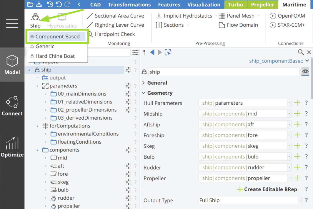
In the Ship Object, an asterisk (*) next to a component indicates that the component is required for the generation of a ship geometry.
This systematic process ensures that all major design features are addressed, resulting in a well-structured, fully-parametric ship model.
Step 1 | Define Hull Parameters
By clicking the plus button next to the Hull Parameters, a component of parameters is created, encapsulating the scopes, as depicted in the figure below.
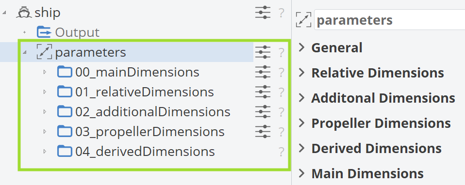
The Main, Relative, Additional and Propeller Dimensions use Design Variables that can be modified as needed. These are numerical values that will ultimately define a meaningful ship hull geometry. The Derived Dimensions use Parameters that calculate the corresponding values based on the aforementioned Design Variables.
Step 2 | Midship
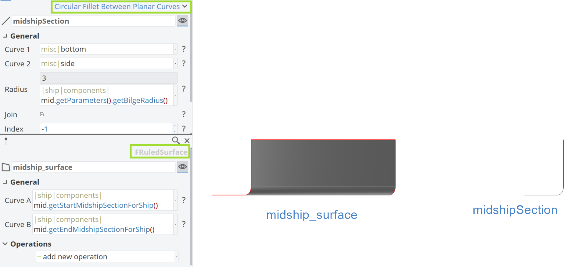
The creation of the Midship follows by clicking the corresponding plus button. This is simply a ruled surface in CAESES, generated from the midshipSection between the parameters xStartMidship and xEndMidship, so no pop-up options will appear. While it is a straightforward geometry, it is a necessary step in the Ship Object structure.
Step 3 | Aftship
Afterwards, the generation of the Aftship can be done by clicking the plus button. Three options will appear, as shown in the figure below.
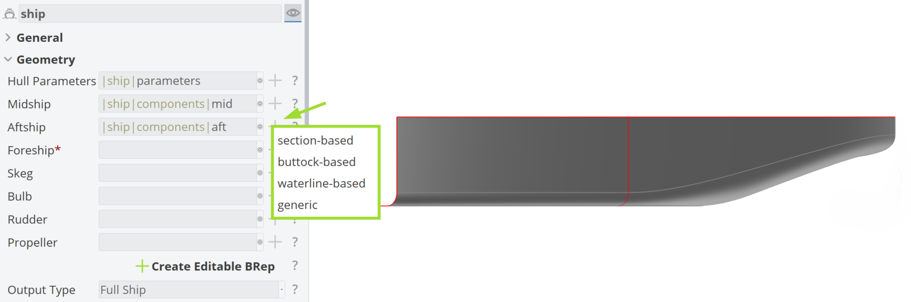
The available options are:
- Section-based: The main surface of the Aftship is based on hull sections.
- Buttock-based: The main surface of the Aftship is based on hull buttocks.
- Waterline-based: The main surface of the Aftship is based on hull waterlines.
- Generic: A custom/existing Aftship can be added to the Ship Object.
| Aftship Type | Description | Suitable Ship Geometric Types | Typical Applications |
|---|---|---|---|
| Section-based | Based on hull sections (NURBS), controllable via sectional area using the weight of intermediate points. Provides flexible and well-controlled transom geometry. | Ships with round sectional shapes | Tankers, bulk carriers, general cargo ships |
| Waterline-based | Based on hull waterlines (B-splines), with waterline fullness controlled by the position of intermediate control points. Transom geometry is not directly controlled but does not need to be full width. | Ships with flatter aftbody sections | Merchant ships, general cargo ships, container ships |
| Buttock-based | Based on hull buttocks (B-splines), controllable via transom geometry, bilge radius, and buttock fullness using intermediate points. Requires a full-width transom. | Ships with very flat aftbodies and a defined bilge at the transom; fast ships | Container ships, RoRo, RoPax, PCTC |
Step 4 | Foreship
The final necessary step for the Ship Object is to create the Foreship part of the hull. The three available options are:
- Waterline-based (F-spline): The main surface of the Foreship is based on hull waterlines.
- Waterline-based (B-spline): The main surface of the Foreship is based on hull waterlines.
- Sweeping: The sweeping foreship is most suitable for high blockage ships, such as tankers and bulkers, and can include a bulbous bow in the main surface.
- Section-based: The main surface of the Foreship is based on hull sections.
- Generic: A custom Foreship can be added to the Ship Object.
| Foreship Type | Description | Suitable Ship Geometric Types | Typical Applications |
|---|---|---|---|
| Waterline-based (F-spline) | Based on hull waterlines using F-splines, controllable via waterline fullness and curvature at the stem. | Very full and round hull forms without bulbs (spoon bows) | Tankers, bulk carriers, Kamsarmax |
| Waterline-based (B-spline) | Based on hull waterlines using B-splines, with waterline fullness controlled by the position of intermediate control points. | Most hull forms, especially full hull forms | Merchant ships with medium to high block (tankers, bulk carriers, general cargo ships) |
| Sweeping | Based on swept NURBS sections, starting at the midship x-plane and ending at the stem y-plane; controlled by two intermediate points. | High-blockage ships with round forebodies and bulbous bows | Tankers, bulk carriers |
| Section-based | Based on hull sections (NURBS), controllable via two intermediate points. | Most merchant ships, particularly slender hulls | General cargo vessels, container ships, RoRo, RoPax, PCTC |
Upon generating the Foreship, a watertight BRep of the full ship is automatically created, as seen in the figure below.
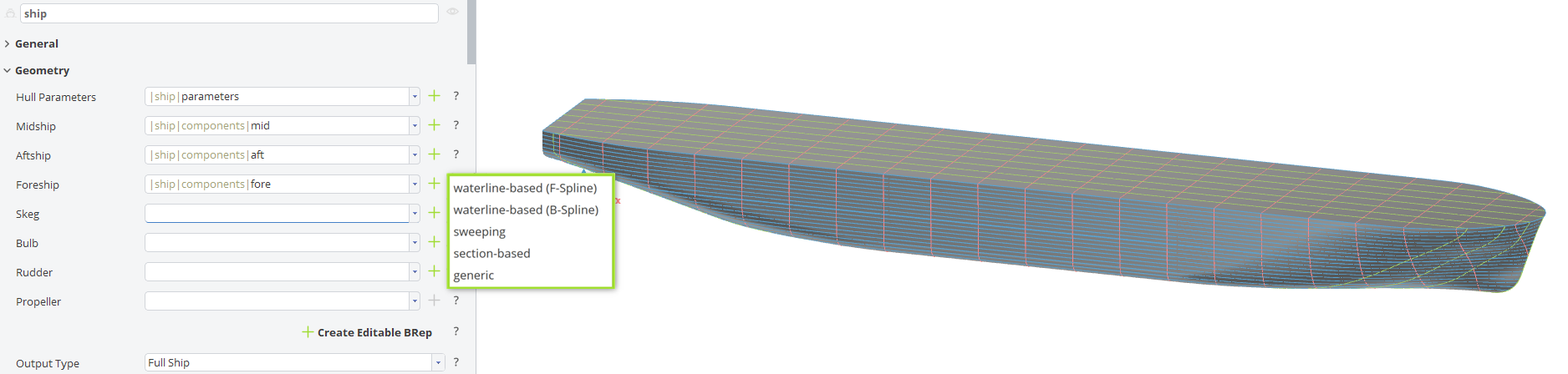
When all required components (Hull Parameters, Midship, Aftship and Foreship) are properly defined, a valid Ship Object is generated. The resulting BRep includes appropriate section visualizations based on the main dimensions of the ship hull.
Step 5 | Skeg & Bulb
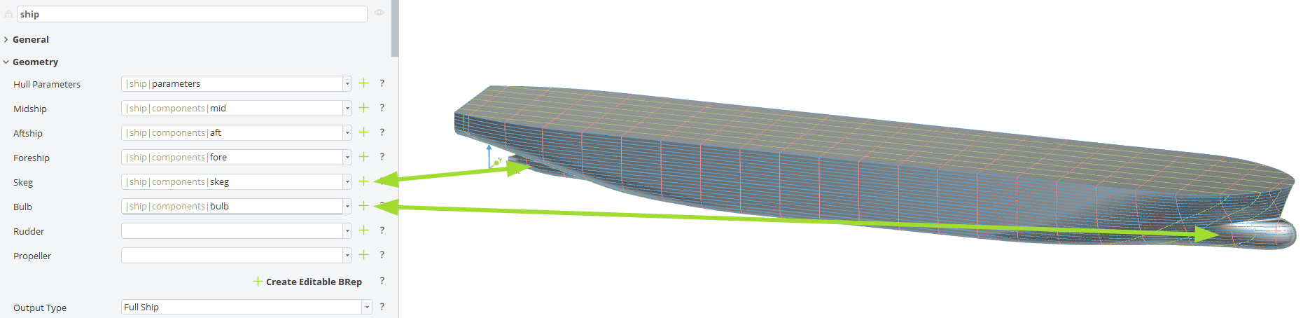
An optional step follows in the geometric workflow. The BRep generated in the previous step can be further modified by adding one or more of the following components to the ship hull:
- Skeg
- Bulb
- Basic: A basic Bulb geometry added to the forebody of the hull.
By clicking the corresponding plus buttons, the modifications will be applied, as shown in the figure below.
Step 6 | Rudder & Propeller
5.4.0The rudder and propeller component require CAESES version 5.4.0 or later.In this optional step, the ship geometry can be completed by adding hydrodynamic appendages that represent the propulsion and steering system. One or more of the following components can be attached to the hull:
- Rudder
- Full-spade: A free-standing Rudder supported only by the rudder stock.
- Semi-balanced: A Rudder with some area ahead of the stock
- Generic: A custom Rudder can be added to the Ship Object.
- Propeller
- Actuator disk: A simplified Propeller representation, typically used for CFD studies.
- Generic: A custom Propeller can be added to the Ship Object.
By clicking the corresponding plus buttons, the selected components are created and positioned relative to the hull, as illustrated in the figure below.
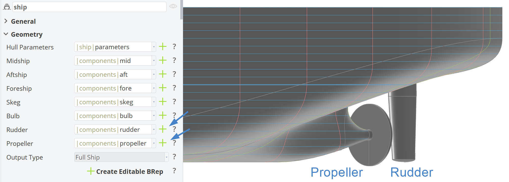
If you use a Twin Skeg as the skeg type, the ship will have twin appendages, i.e., twin rudders and twin propellers. These are not located on the center plane (y = 0), but at a lateral position yProp, which can be found in the Parameters component under the 03_derivedDimensions scope.
When using the Planar Center Plane Skeg, a twin rudder setup is applied, and it is not possible to create a propeller component via the plus button in the Component-Based Ship Workflow.
Create Editable BRep
If you need to further edit the BRep from the Ship Object, you can click on the Create Editable BRep This will create a BRep named "editableShip", which uses the ship geometry generated in the Ship Object as its source. This allows the user to add operations or any other post processing steps.
Additionally, proper section visualization is included in the generated BRep, based on the main dimensions of the ship hull.
The editableShip does not include ship appendages such as the Rudder and Propeller. This makes it more convenient to streamline the bare hull for CFD analysis. If required, appendages can be added to the final BRep during post-processing.
The Ship Object is connected to the editableShip BRep. However, any further operations added to this BRep, will not be reflected in the Output of this Ship Object.
Create a Generic Ship to use the transformed geometry in the Hydrostatics.
Output Type
The available output types are the BRep options that can be obtained from the ship.getShip() command in the Ship Object:
- Full Ship: The complete ship geometry.
- Half Ship: Half of the ship geometry, since ship models are typically symmetric.
- Half Ship without Deck and Transom: A reduced geometry intended for Shipflow computations.
The editableShip BRep, created via the Create Editable BRep button, uses the ship.getShip() command as its source. Therefore, the selected Output Type directly affects this geometry.
CAESES Project File
If you want to take a look at the finalized model you can find the resulting CAESES project file component-based-ship-workflow.cdb here: