BReps and Solids
CAESES provides capabilities to create solid geometry. The main CAESES object for this task is the BRep (coming from the term "Boundary Representation"). Boundary Representations (BReps) are surface or volume geometries that are mathematically defined by their boundary surfaces. BReps are widely used in CAD systems for creation of trimmed surfaces, watertight geometries and fillet operations.
In addition, the color settings of BReps are used to create unique and fixed identifiers for automated meshing and simulation processes. STEP or STL files will transfer the color information as a name information so that you can refer to it in recorded meshing routines, for instance.
The tessellation and rendering can also be controlled with a set of properties, to define the triangle data in case you want to export STL data.
As a result, BReps can be used for more tasks than just for creating solids. BReps allow you to do:
- Boolean Operations
- Extrude Operations
- Trimming Operations
- Closing Bodies
- Fillet Modeling
- Control Surface Meshes (Accuracy, Triangulation)
- Create Face Identifiers through Color Settings
BRep Creation
In order to create a new object, choose
- Model > CAD > BReps > BRep
Typically, you start with a new operation in the next step, to add surfaces or other BReps. See the section BRep Operations below.
Edge Colors
For a generated BRep, you can observe different colors of the edges:
- Grey: Closed and clean edge
- Red: Open edge
- Magenta: More than 2 partner edges

Typically, you would try to create a clean geometry with grey edges (2 matching partner edges). If inner regions show a red edge, you probably have to check your geometry model. Even though it looks like edges are matching, there might be minor numerical differences which make your edges non-matching.
Edge Usage
There are different methods available to reference an edge of a BRep.
Reference by Edge ID
When you hover over the edges with the mouse cursor, you can select and potentially use the edges for modeling. They are simple curves (type FCurve). However, the expression e.g. myBody.getEdge(12) returns a specific edge that is not necessarily the same edge for another design variant, i.e., when you change the model using your model parameters. For instance, specific Boolean Operations and filleting processes can assign another index to the edge so that e.g. myBody.getEdge(29) would return the same edge again.
Referencing edge curves via edge ID, e.g. for use in image curves etc., should be avoided and is only safe for fixed BRep parts, see the section BRep Parts below. Edge IDs may vary for different model variants, if edges are added or removed.
Edge Loops
If you want to get the edges of an open loop you can use the curve Open Edge Loop via Model > CAD > Curves > BRep based > Open Edge Loop

If there are more than one open loop in the BRep, you can specify the loop by a reference point. As shown in the image above, you can also access the tangent edge.
Edge from Operation
This curve will give you the curve from a BRep projection or intersection. You can create this curve via Model > CAD > Curves > BRep based > Edge or Tangent Edge

Face Usage
Similar to the BRep edges, you can access the underlying untrimmed faces. You can easily create an Image Surface from a face:
Note that the face ID might change during the geometry variation!

Closed Bodies
A closed BRep body shows only grey edges. For closed BReps, the BRep icon changes from a standard icon to a filled one. This gives you a visual confirmation particularly in the object tree that you are having a solid geometry.
![]()
With the command BRep.getNumberOfOpenEdges() you can check the number of open edges of your final model.
BRep Operations
The idea of using BReps is that you start with an initial geometry and then apply a set of operations to it. The operations are in a specific order, so that they can be applied again if the initial input geometry changes, e.g. during design studies and optimization runs.

In order to activate an operation, click on the toggle button at the left-hand side of the operation. There is also a handle to change the order of the operation. On the right-hand side, there is a button to edit the operation.

Add Sources
This operation allows you to add an initial geometry. This can be curves, surfaces or BReps. Matching edges will be sewn.
Boolean
Boolean Operation
This operation provides the Boolean Operations
- Union
- Intersection
- Difference
- ExclusiveOr
- Merge
- Imprint
Boolean Operations always need a closed input geometry (no open edges).
A Boolean operation can optionally include a fillet creation as an integral part of the operation. This is offered as a convenient mechanism. There is also a separate fillet operation available, see the section Edge Fillet below.

Solid from Intersections
Similar to the Boolean Operations, this operation can help you create a solid based on the intersecting geometry that you provide. It can create a solid from an open body and intersecting surfaces, whereas the Boolean Operation always needs closed input.
This operation is also often used in combination with the integrated filleting capability (see the Boolean Operation).
Closing
Faces from Planar Curves
This can be an initial operation of a BRep, where you provide e.g. a circle as input and this operation will create a 2D face from it (that can then be extruded in a next operation etc.).
Close Non-Planar Holes
This operation attempts to close non-planar holes of your geometry.
Close Planar Holes
Similar to the one from above, this one is for planar holes.
Close Planar Open Edges
This operation finds and closes planar open BRep edges. The planar edges, which are closest to the reference point will be used and closed. Afterwards a planar face is created and added to the BRep.
This operation is especially useful for the deck modeling of an open ship hull. See the tutorial Planar Transom and Deck Modeling for a step-by-step guide.
Trimming
Cut Min Max
This operation allows you to cut the geometry in x-, y- and z-direction using optional lower and upper bounds for each axis.
Intersect and Trim
This operation allows you to trim a geometry based on some source geometry (e.g. trim a body by means of another surface).
You also need to specify which part of the processed geometry shall be trimmed i.e. removed, and which part to be kept. This is done through creating a 3D vector position and projecting it onto the geometry using a direction. You can then tell CAESES whether to keep or remove the part where the projected position is found.
Such a projection mechanism makes sure that you trim the correct part even if the geometry changes during automated design studies.
Project and Trim
Similar to the previous operation, the trimming is defined by means of identifying geometry through a projection process.
Remove Faces
This operation allows you to remove a face or a set of faces where the color of the faces is taken as reference.
Edge Fillet
This is a separate operation which allows you to create a fillet between surfaces where two different colors are used to identify where the fillet should be applied to. For instance, you can create a fillet between the green and the red part of geometry.
The filleting category has a few more options, such as
- Fillet cross-section shape
- Bevel option
- Fillet type (radius, distance)
- Tolerance
- Color
Extrusion
Extrude Edges to Plane
This is an extrude operation where a plane provides the target information. Note that you can specify a color for the extruded but also for the closing geometry, to assign unique identifiers.
Extension from Open Loop
This operation will detect all open edges which are loops. If there are more than one open loop, you can set the reference with a point. This loop can then be extended.
Coloring
Remove Color
Sometimes it can be helpful to remove one specific color or all the color information, e.g. to start a new operation chain or just for visualization purposes. This operation removes one color or, alternatively, all color information from the BRep.
Replace Color
If the BRep has colored faces, the assigned colors can be replaced by a new color.
Color Patch by Point
This operation will set the color of a face closest to the reference point.
Color Region by Intersection
This operation can be used to split the BRep into two parts and set different colors on those parts. The object for the intersection needs to fully intersect the BRep.
Colors
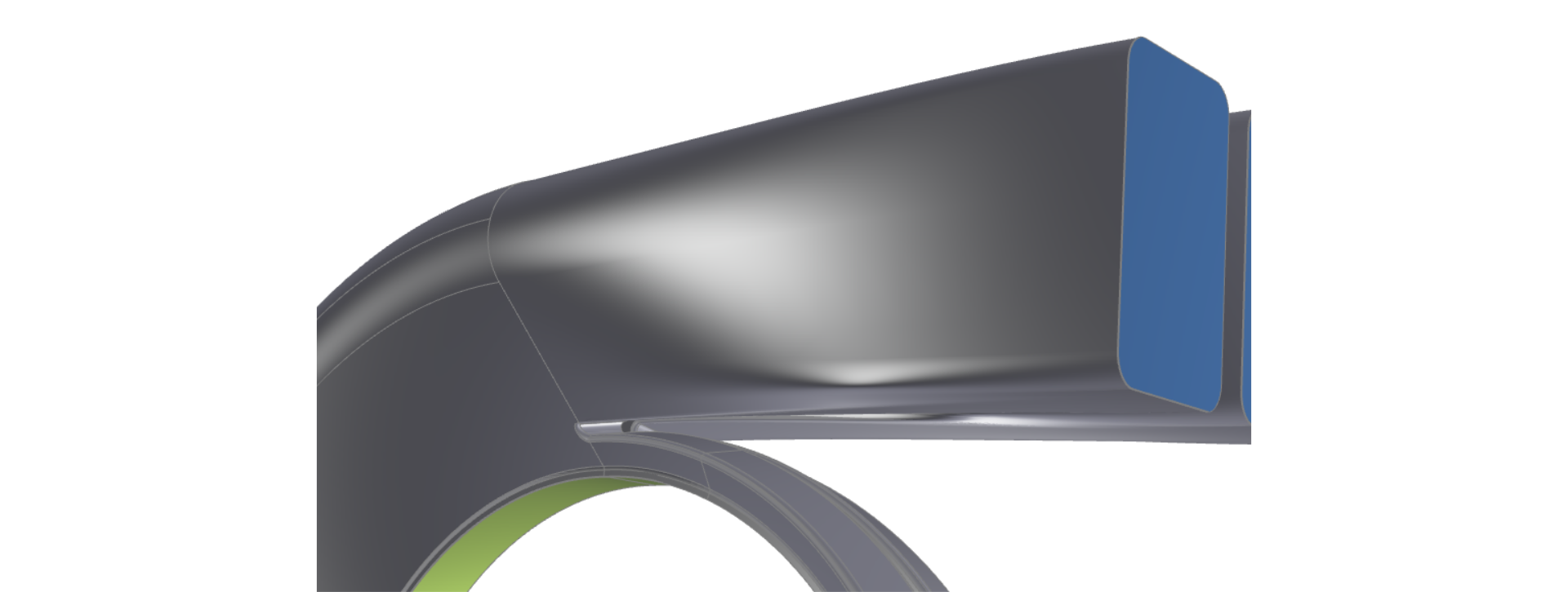
An essential part of working with BReps is the use of colors. You can either use the colors that are provided by CAESES, or you create your own ones with custom names.
Custom names will then be transferred as identifiers within the exported files (STEP, IGES, Parasolid, STL). As a result, you can use these identifiers in your external CAE tools, e.g. for automating meshing procedures and for referencing them in general.
Object Color
There is the standard object color so that you can assign a color to the entire BRep object. This color is then taken for all faces, including faces that are generated during the operations.

Operation Color
Within each operation, you can also assign an individual color and hence replace the global object color for specific patches. For instance, you can create a planar face and assign a color with the name "outlet" to it. The remaining faces still hold the object color (silver in the screenshot below).

It is important to know that once a face of a BRep has a color, this color will not be overwritten by any other coloring process.
In the images below the end faces of the duct are closed with specific colors. The duct's wall did not get a color in the first Add Sources operation. So when we set the color brown to the complete BRep, then only the wall face gets the new color (since it had no color setting before). If you want to overwrite a color, you can use the operation Remove Color.

Triangulation and Rendering
The BRep object contains "Display Options" to hide underlying data or to make it visible. Additionally, a BRep provides properties to control the triangulation (tessellation). The latter is particularly important if you want to export STL data where you want to control the resolution and density of the surface mesh.
Display Options
The display options for BReps are similar to the display options of surfaces. The main difference is the purpose of usage. The most important options for BReps are listed below and help you evaluate the quality of your BRep visually.
- Show Control Polygon (to display the underlying NURBS control points),
- Show Triangles (to visualize the tesselation settings) and
- "Display All Edges" (to show open (red) and closed (gray) edges)
Tesselation Settings
In the category "Tesselation" of a selected BRep, check the following properties which help you to control the triangulation:
- Max. Chord Height
- Angle Tolerance
- Max. 3D Length
Switch on the rendering of the triangulation to easier judge your settings.

You can also propagate the triangulation so that CAESES tries to keep these settings, even if this BRep is used within other BReps (which also have their own settings for the triangulation).
BRep Edit Mode
Local Patch Settings
If you click on the edit button in the upper right corner of a selected BRep, you can configure the color and triangulation individually for each patch. Just select the patch during the edit mode and change the settings:

Such a local setting is useful if you have faces or parts for which you want to increase the resolution, while not increasing the resolution of the other faces (to keep the amount of data as low as possible).
Local Face Removal
It is also possible to remove patches from a BRep. Therefore we can utilize the edit mode again:

You can hold the Ctrl key for a selection of multiple patches. In the Post Processing category, you can also edit and invert the selected faces.
Extend Selection
If you want to select many connected patches, you can also use the Extend Selection option. With that option you select one face and then automatically all faces, which are connected to this patch are selected. This can be helpful for instance of you want to extract the fluid faces from a solid model:

Post Processing
The BRep object contains a category Post Processing where you can enter transformations such as scaling or a translation. Note that these transformations are applied after the operation chain update.
Data Reduction and Refinement
If you expand the Post Processing category, you'll find more options to reduce or to refine the underlying NURBS data. For instance, you could refine the data to have more control vertices available when applying shape deformation techniques. And you could reduce it with regards to a sufficient accuracy, to bring down the overall data amount when exporting it.

Knot Spacing
The Knot Spacing sets the absolute maximum distance between NURBS knots on the surfaces of the BRrep, which corresponds directly to the number of control vertices of the underlying NURBS surfaces of the BRep. This is only relevant for shift transformations or BRep morphings.
If a value is set, then knots are inserted into the surfaces with this maximum allowed distance between knots.
Shift transformations and morphings get applied to the control vertices of the underlying NURBS surfaces of a BRep (and not to the surface directly). The higher the number of control vertices, the more accurate is the shift transformation.
This knot insertion also increases the data amount of the BRep, and affects the update performance.
If you like to reduce the data amount after a shift again, then use the Data Reduction Tolerance option. It removes the knots and the vertices again according to an absolute accuracy tolerance.
In order to visualize the net of control vertices, activate the show control polygon in the Display Options category.

Make sure to check the help (? icon next to the property settings) for more details.
BRep Parts
When you import NURBS geometry using the STEP or IGES import in CAESES, you will receive objects in the object tree that are called BRep parts. You can also find this type in the menu CAD > BReps > BRep Part.
BRep parts represent a fixed geometry, i.e., geometry that is not variable or parameterized in CAESES. Often, these geometries serve as a reference or provide a fixed part of an assembly.
External Reference
You can also use BRep parts to load in external (fixed) BRep data. Any BRep object in CAESES can be stored on your hard disk in a separate file (*.part). This file can then be referenced by the BRep part. Alternatively, you can reference and load data even from an existing CAESES project (*.cdb, *.cdbc).
Such a reference keeps your current setup lightweight. Another advantage here is that you can build up your parametric model where you include the BRep part, and then replace the underlying data base at any time - your model will not break, all dependencies will be kept.
