Ahmed Body Modeling and OpenFOAM Connection
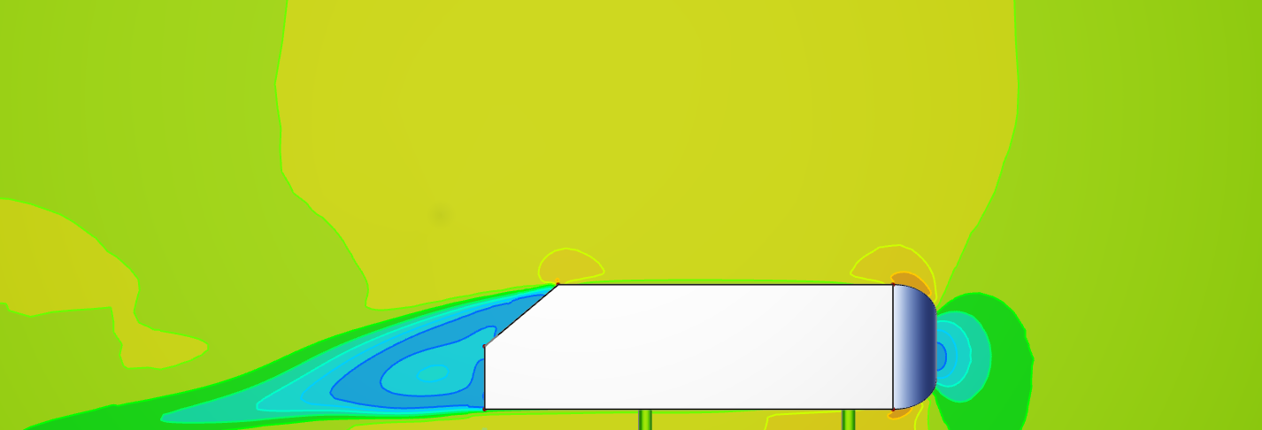
In this tutorial, you will learn how to model the Ahmed Body, which is a simplified, standardized vehicle model widely used in computational fluid dynamics (CFD) research and automotive aerodynamics. In the second part of the tutorial you will learn how to connect an OpenFOAM with CAESES and how to visualize the results.
- Start by downloading the CAESES project, which will be our starting point:
The starting project file does not contain any geometry yet. However, it comes with a starting point for the OpenFOAM software connection in the Connect workspace.
Ahmed Body Modeling
Parameters
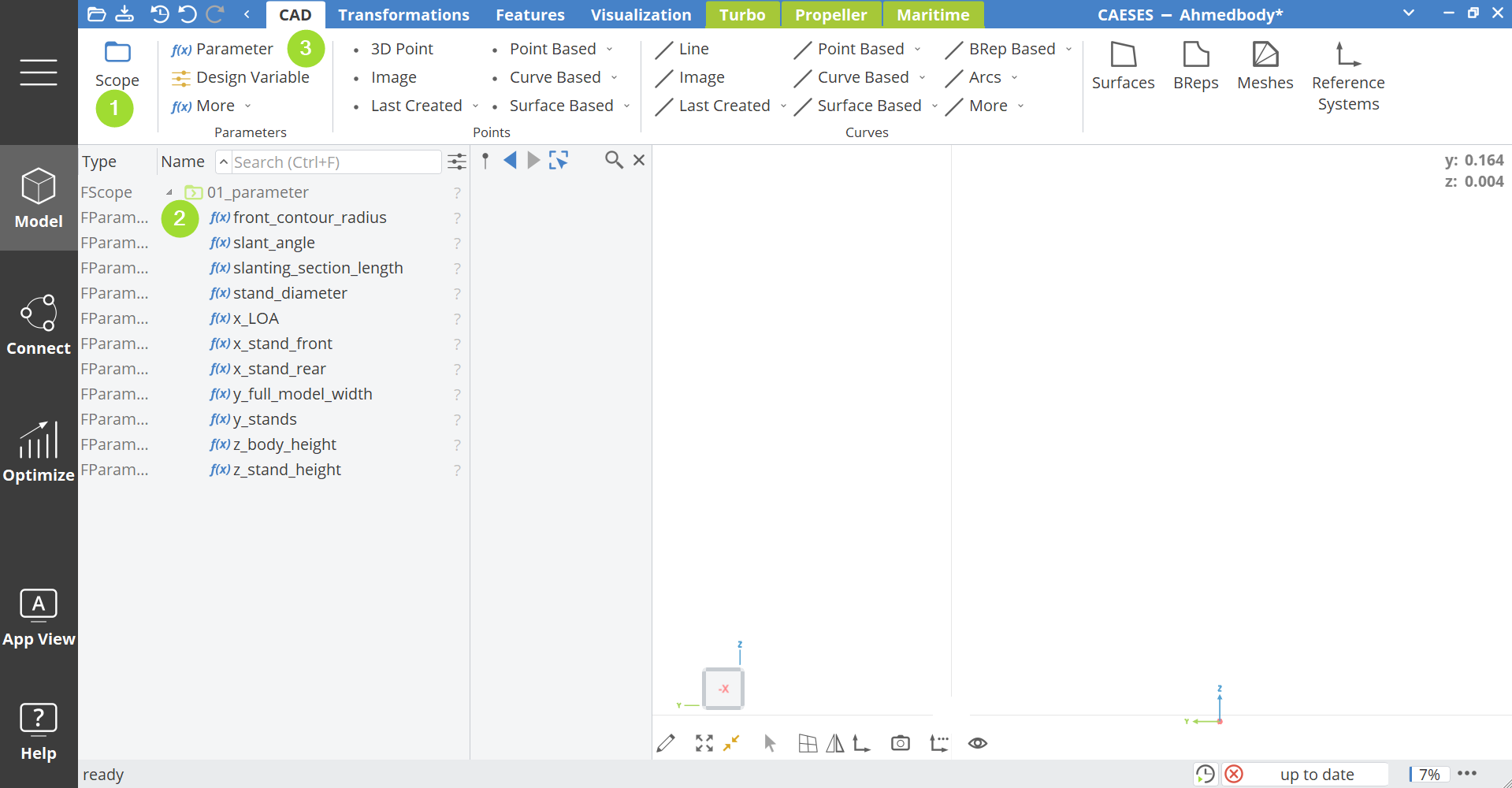
In the first step, create all parameters that define the parametric geometry of the Ahmed Body and can later be used in an optimization process if converted to Design Variables with bounds.
- Create a Scope via Model > CAD > Scope and set the name to 01_parameter.
- Turn this scope into the Working Scope by clicking on its symbol in the tree with the middle mouse button. This ensures that all newly created parameters are stored inside this scope.
- Create the Parameter via Model > CAD > Parameter and set:
- Name:
x_LOA - Value:
1.044
- Name:
- Create additional parameters as shown in the following table:
| Parameter Name | Value |
|---|---|
front_contour_radius | 0.1 |
y_full_model_width | 0.389 |
z_body_height | 0.288 |
slant_angle | 40 |
slanting_section_length | 0.222 |
x_stand_front | -0.842 |
x_stand_rear | -0.372 |
y_stands | 0.1635 |
z_stand_height | 0.05 |
stand_diameter | 0.03 |
Points
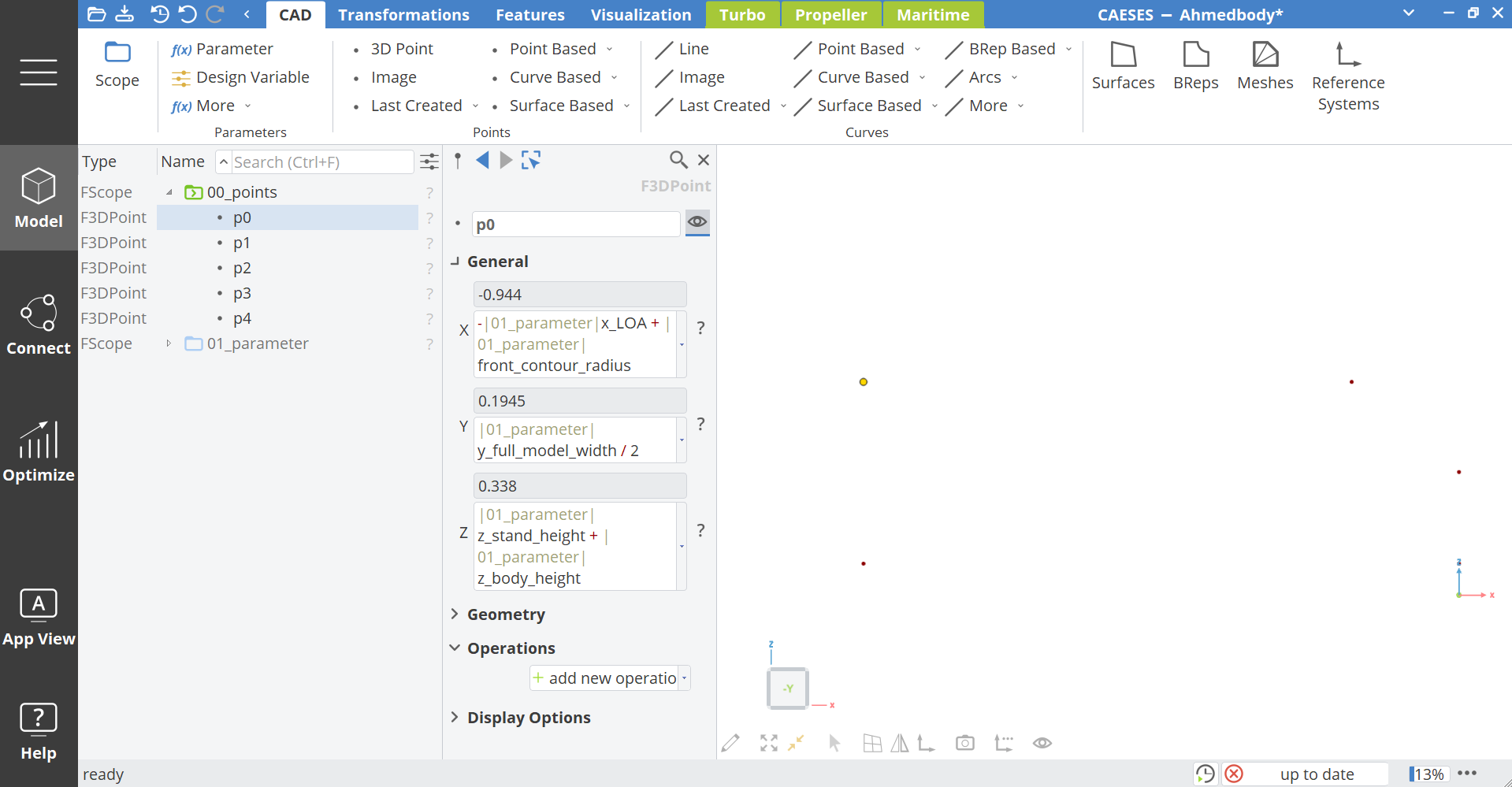
Utilizing the above created parameters, we create parametric points which will be used for the outline of the Ahmed Body.
- Create a new Scope via Model > CAD > Scope and name it
00_points. - Create a 3D Point via Model > CAD > Points > 3D Point.
Enter the following coordinates:
- X:
-|01_parameter|x_LOA + |01_parameter|front_contour_radius - Y:
|01_parameter|y_full_model_width / 2 - Z:
|01_parameter|z_stand_height + |01_parameter|z_body_height
and set its name to p0.
Create four more points with the following values:
p1
- X:
-(cos(|01_parameter|slant_angle) * |01_parameter|slanting_section_length) - Y:
|01_parameter|y_full_model_width / 2 - Z:
|01_parameter|z_stand_height + |01_parameter|z_body_height
p2
- X:
-|01_parameter|x_LOA + |01_parameter|front_contour_radius - Y:
|01_parameter|y_full_model_width / 2 - Z:
|01_parameter|z_stand_height + |01_parameter|z_body_height
p3
- X:
-|01_parameter|x_LOA + |01_parameter|front_contour_radius - Y:
|01_parameter|y_full_model_width / 2 - Z:
|01_parameter|z_stand_height + |01_parameter|z_body_height
p4
- X:
-|01_parameter|x_LOA + |01_parameter|front_contour_radius - Y:
|01_parameter|y_full_model_width / 2 - Z:
|01_parameter|z_stand_height + |01_parameter|z_body_height
Curves
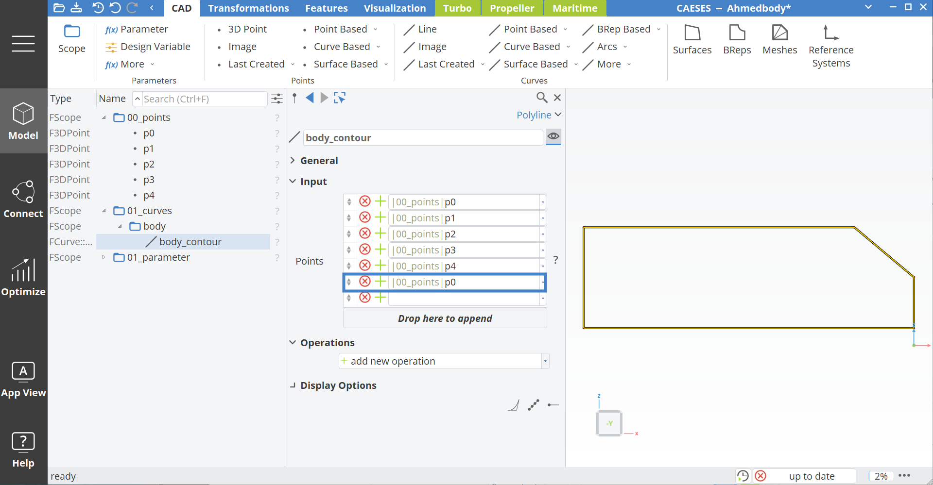
From the created points, curves representing the contour of the body are generated. The geometry is divided into a body and stands.
- Create a new scope via Model > CAD > Scope and name it
01_curves. - Inside this scope, create another scope named
body. - Select it with the middle mouse button to make it active (green scope icon).
- Select all points from
00_pointsand create a curve via Model > CAD > Point Based > Polyline. - Rename this curve to
body_contour.
To close the contour, the first point (p0) must be listed twice in the Polyline input – once at the beginning and once at the end.
- In the curve settings under Input > Points, add another point at the end by writing in the empty field:
|00_points|p0.
Rounded Front – Upper Part
To model the rounded front upper contour of the Ahmed Body:
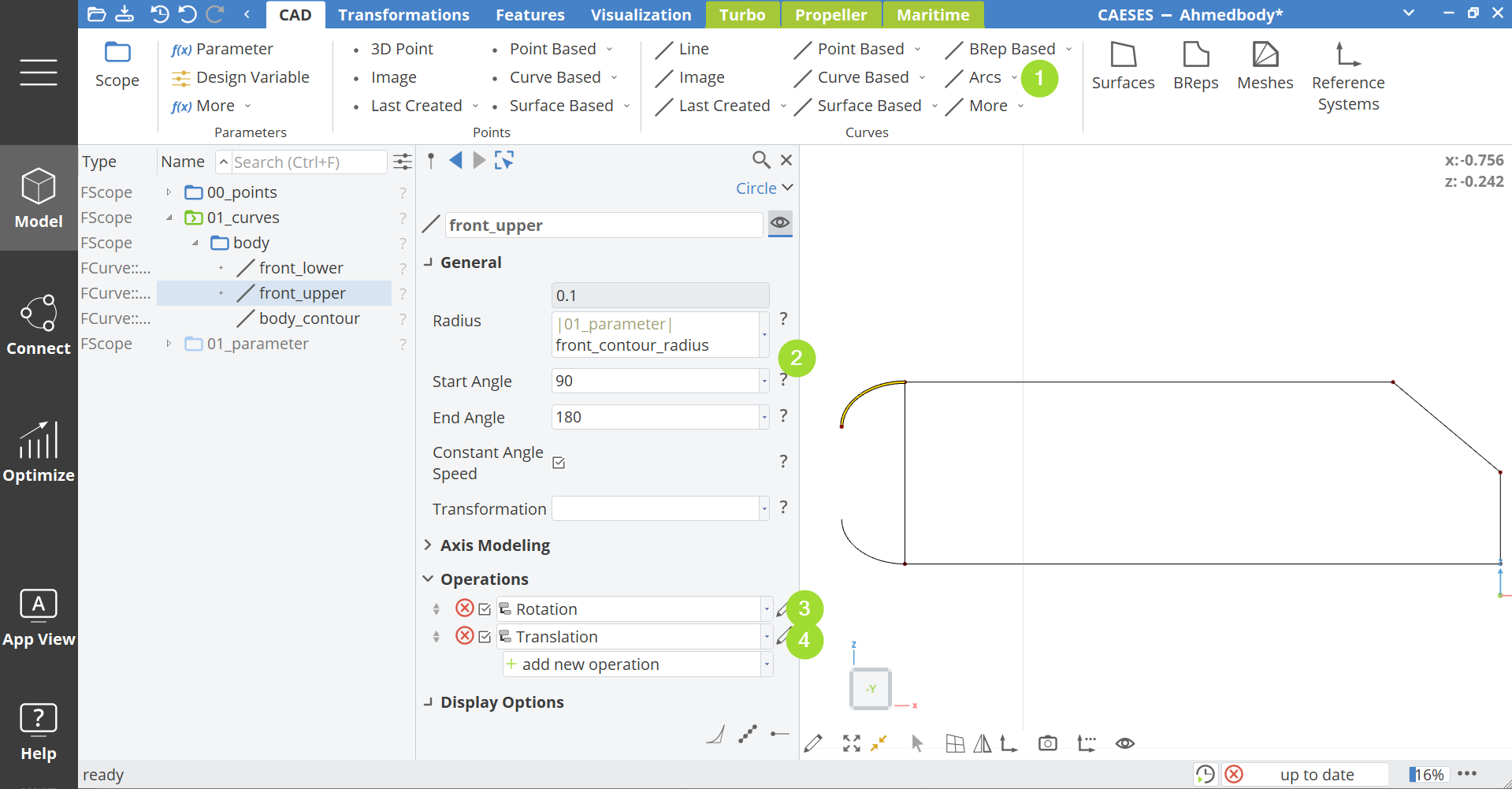
- Create a Circle Arc inside the scope 01_curves > body via Model > CAD > Arc > Circle and name it front_upper.
- Set the arguments as:
- Start Angle:
90 - End Angle:
180 - Radius:
|01_parameter|front_contour_radius
- Start Angle:
- Add a new operation via add new operation > Transformations > Rotation and set the arguments:
- Angle:
-45 - Origin:
[0, |01_parameter|front_contour_radius, 0]
- Angle:
- Add another operation via add new operation > Transformations > Rotation and set the arguments:
- Dx:
|00_points|p4:X - Dy:
|00_points|p4:Y - |01_parameter|front_contour_radius - Dz:
|00_points|p4:Z
- Dx:
Rounded Front – Lower Part
Similarly, for the front lower contour:
- Create a Circle Arc inside the scope 01_curves > body via Model > CAD > Arc > Circle and name it front_lower.
- Set the arguments as:
- Start Angle:
90 - End Angle:
180 - Radius:
|01_parameter|front_contour_radius
- Start Angle:
- Add a new operation via add new operation > Transformations > Rotation and set the arguments:
- Angle:
45 - Origin:
[0, |01_parameter|front_contour_radius, 0]
- Angle:
- Add another operation via add new operation > Transformations > Rotation and set the arguments:
- Dx:
|00_points|p0:X - Dy:
|00_points|p0:Y - |01_parameter|front_contour_radius - Dz:
|00_points|p0:Z
- Dx:
Stands
The next step is to model the stands of the Ahmed Body.
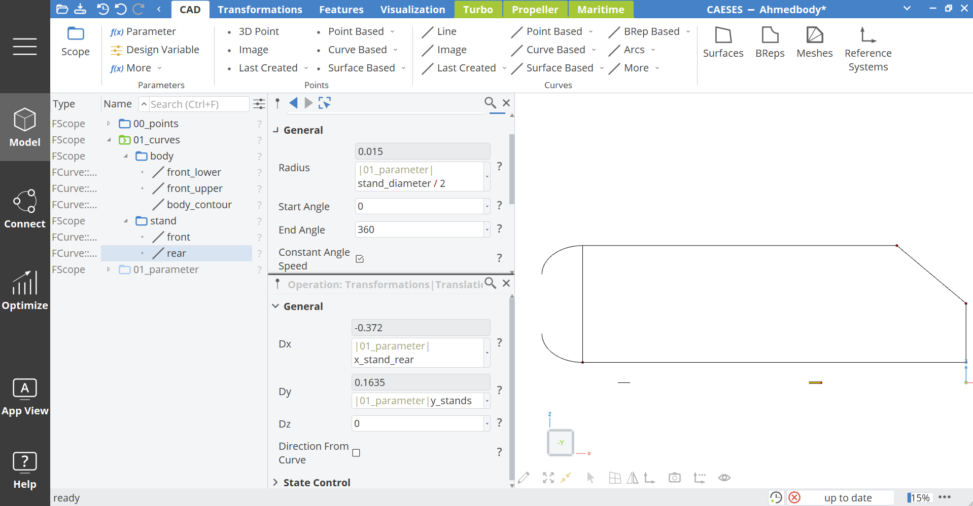
- Inside
01_curves, create another scope via Model > CAD > Scope and set the name tostand. - Create a Circle Arc via Model > CAD > Arc > Circle and set the following arguments:
- Name:
front - Radius:
|01_parameter|stand_diameter / 2 - Add a new operation via add new operation > Transformations > Translation
- Set Dx to
|01_parameter|x_stand_frontand Dy to|01_parameter|y_stands
- Name:
- Select the arc
frontin the tree and create another arc via Model > CAD > Arc > Circle with the arguments:- Name:
rear - Add a new operation via add new operation > Transformations > Translation
- Set Dx to
|01_parameter|x_stand_rearand Dy to|01_parameter|y_stands
- Name:
Surface and BReps
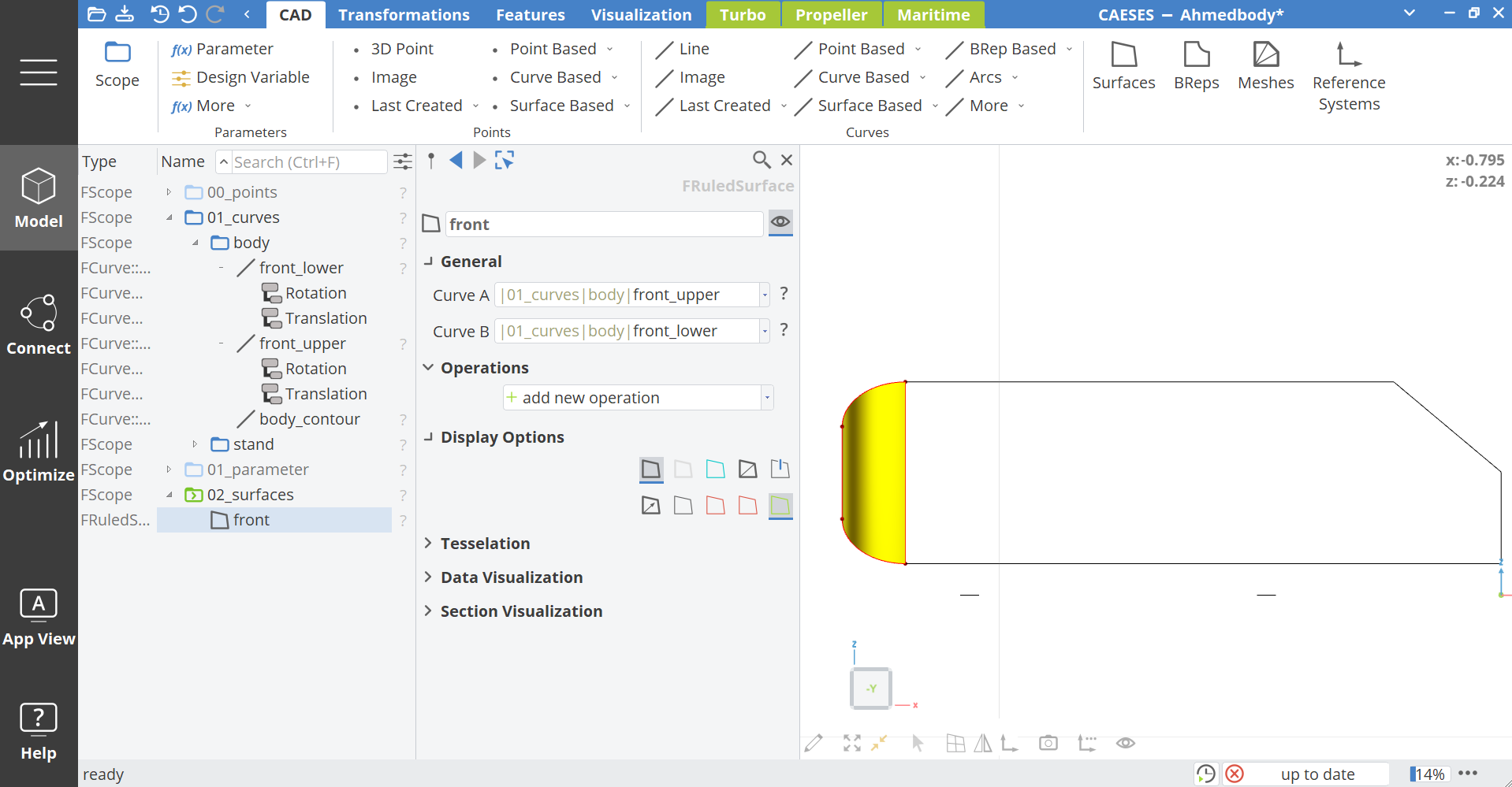
In this step, a surface is created from the two curves of the rounded front. With this surface and the body contour curve, a BRep can be created and extruded. The stands are also modeled in this step by extruding the stand curves.
Front Surface
- Create another scope via Model > CAD > Scope and set the name to
02_surfaces. - Inside this scope create a Ruled Surface via Model > CAD > Surface > Ruled and set the name to
front. - For Curve A select
|00_half_model|01_curves|body|front_upperand for Curve B select|00_half_model|01_curves|body|front_lower.
BRep Body
- Create another scope via Model > CAD > Scope and set the name to
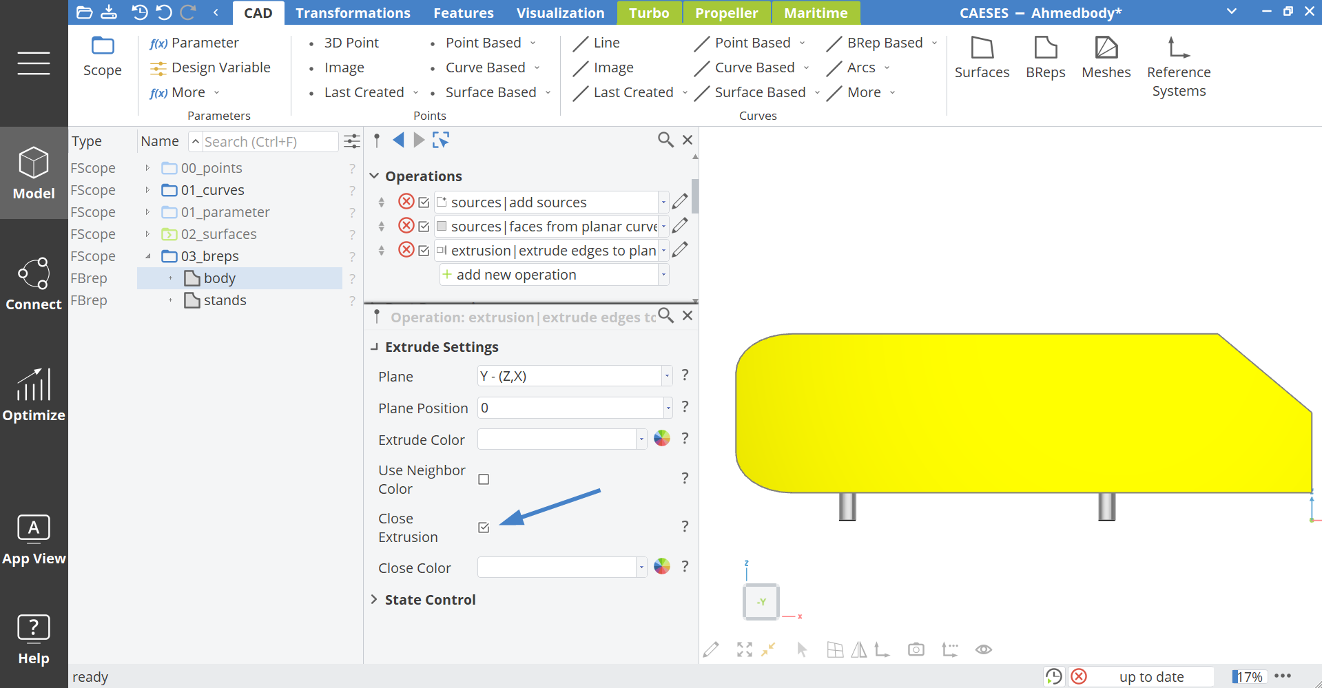
03_breps. - Inside this scope create a Brep via Model > CAD > BRep and name it
body. - Click the pencil icon next to Operations > Sources | add sources.
- Fill in the Sources:
02_surfaces|front. - Add the operation Face from Planar Curves to body via add new operations > Closing > Face from Planar Curves.
A window with sources opens automatically.
- Add into Sources:
|01_curves|body|body_contour.
To create a three-dimensional body, the BRep will be extruded.
- Add the operation Extrude Edges to Plane via add new operations > Extrusion > Extrude Edges to Plane.
- Inside the extrude settings select for Plane:
Y-(Z,X)and for Plane Position:0. - Also enable the Close Extrusion checkbox.
The stands are extruded as well.
- Create another
BRepvia Model > CAD > BRep and name itstands. - Click the icon next to Operations > Sources | add sources.
- Fill in the Sources:
|01_curves|stand|frontand|01_curves|stand|rear. - Add the operation Extrude Edges to Plane via add new operations > Extrusion > Extrude Edges to Plane.
- Inside the extrude settings select for Plane:
Z-(X,Y)and for Plane Position:|01_parameter|z_stand_height + 0.01. - As for the body, also activate for stands the Close Extrusion checkbox.
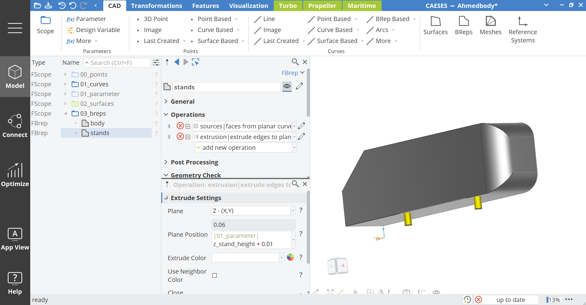
To store everything in one scope:
- Select
00_points,01_curves,02_surfaces,03_brepsand create another scope via Model > CAD > Scope and set the name to "00_half_model".
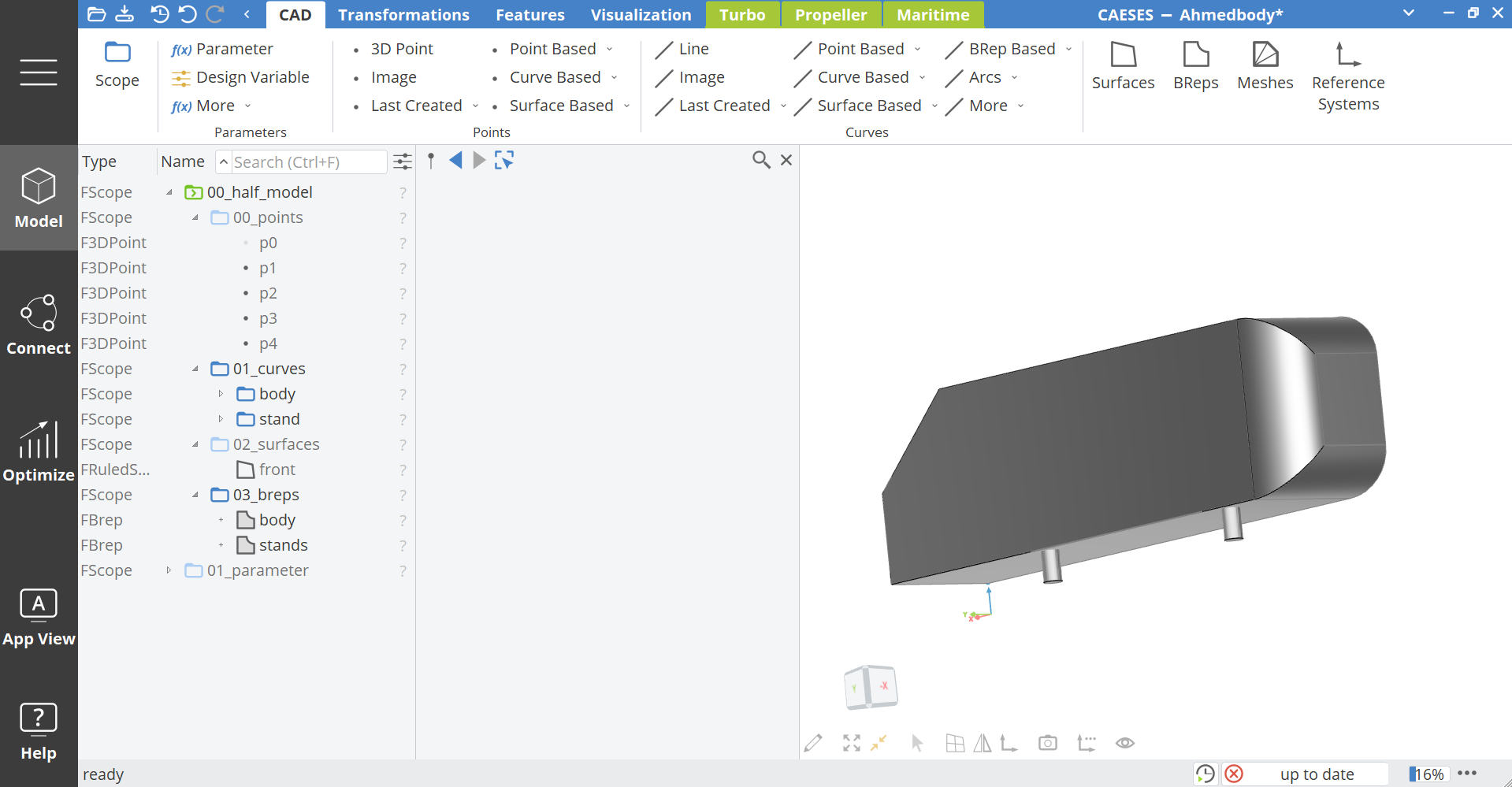
OpenFOAM Setup
In this step an OpenFOAM connection will be created.
OpenFOAM Files
An OpenFOAM setup for the Ahmed Body is already imported in this project.
- Set the workspace with the left navigation bar to Connect.
- Click on the already existing
ahmed_bodysoftware connection via Connect > Connection > Computations > ahmed_body.
On the right you can see in the Input Files area all the relevant OpenFOAM files. You can add more or different files if needed by drag and drop or by clicking on the plus icon in the upper left corner of the Input Files.
- Double-click on the file
BlockMeshDictto open it inside CAESES.
To create the correct folder structure of OpenFOAM, the name of each file needs to contain the relative file path.
- Change the name of the
BlockMeshDictvia the field next to Template Name tosystem/blockMeshDict.
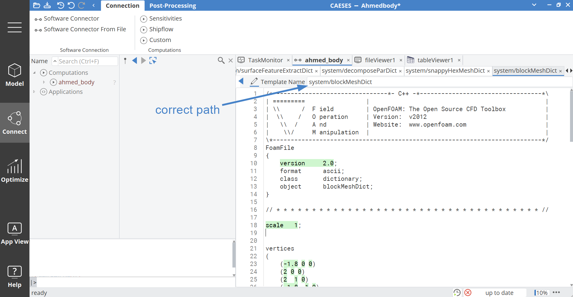
- Do the last two steps with all the other files as well and change the names as shown in the picture.
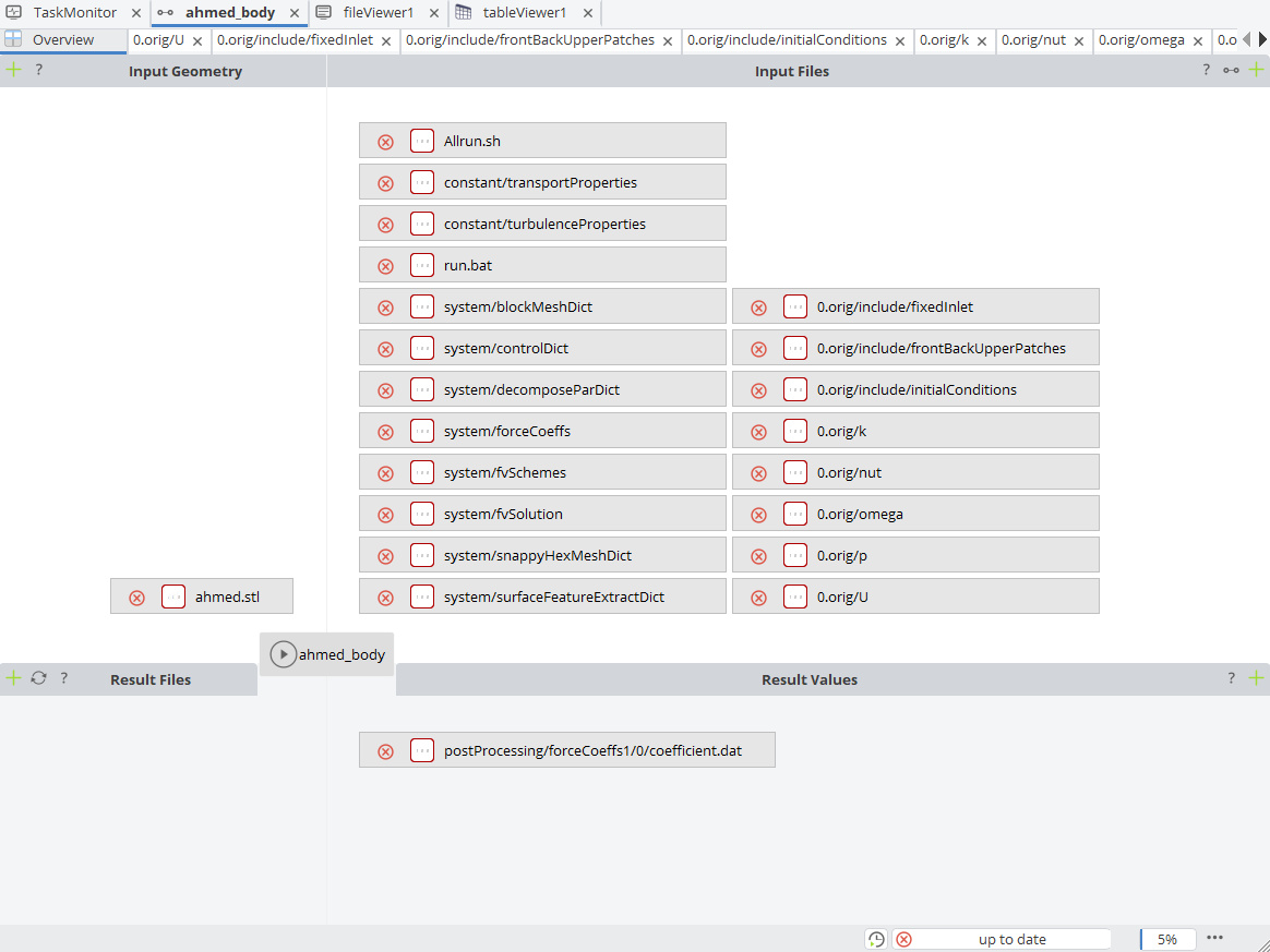
The OpenFOAM commands are executed via an Allrun.sh script.
If you use the Windows version of CAESES, WSL2 (Windows Subsystem for Linux) can be used to run OpenFOAM, since OpenFOAM is a Linux-based application only.
- WSL2 must be installed and configured.
- OpenFOAM must already be installed in WSL.
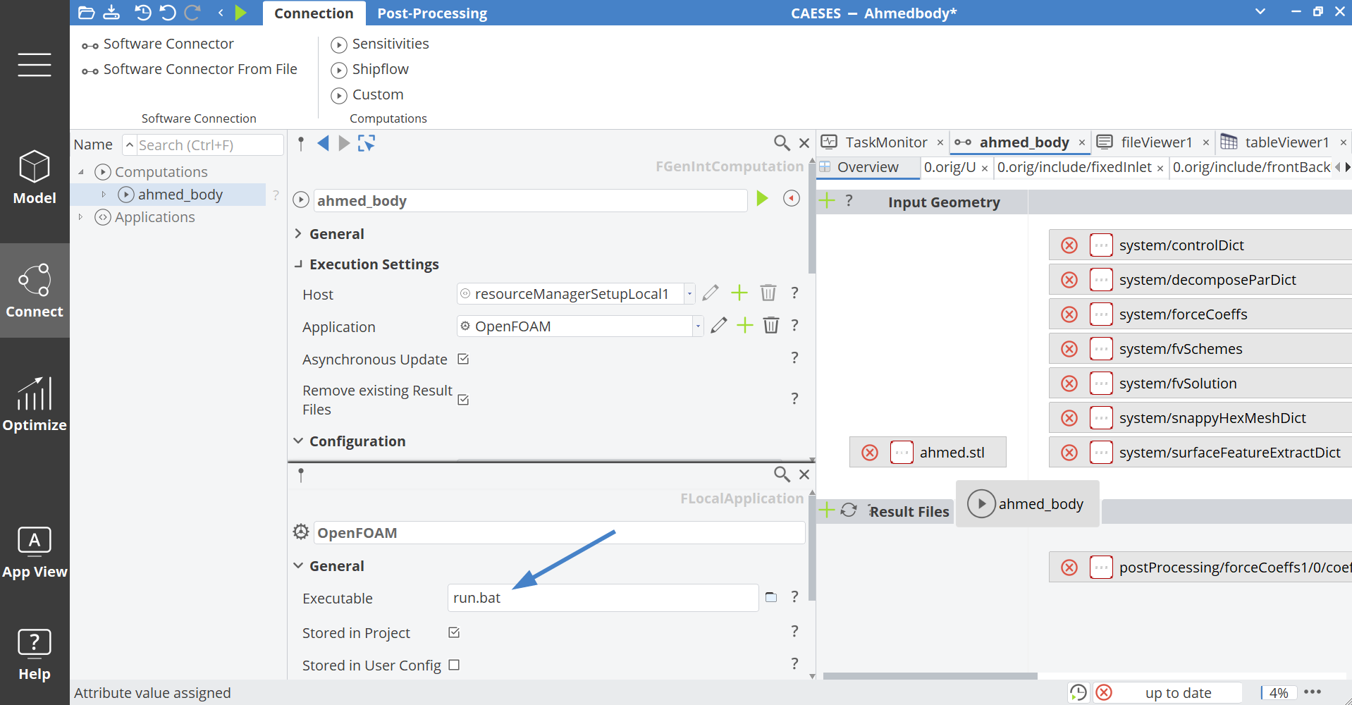
To start WSL and run the Allrun script, a run.bat file is used.
This batch file is triggered directly from CAESES via the connector.
- Click on the computation
ahmed_bodyvia Connect > Connection > Computation > ahmed_body. - In the Execution Settings, click the plus icon next to the Application field to create a new application.
- Name the new application: "OpenFOAM"
- In the field Executable, enter:
run.bat
If you run CAESES on linux, the batch script is not needed and you can directly use the Allrun.sh file.
Export Geometry
In this step, the geometry for OpenFOAM will be specified.
- Create a new scope via Model > CAD > Scope and set the name to "02_OpenFOAM".
- Inside this scope, create another Scope named "00_geometry".
- Inside
00_geometry, create a BRep via Model > CAD > BRep and name itexport_geometry. - Add sources by clicking the icon next to Operations > Sources | Add Sources and fill in the Sources:
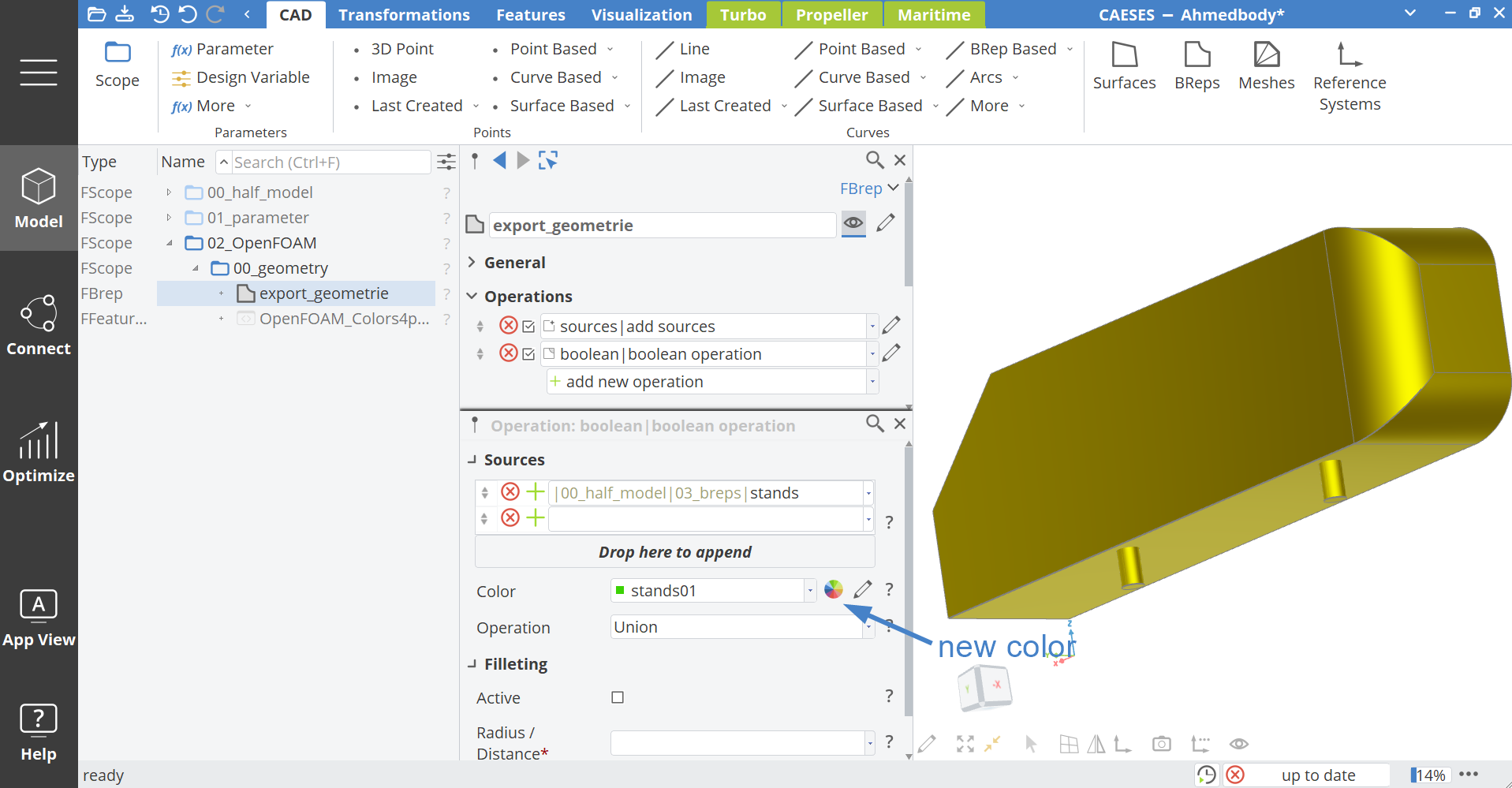
|00_half_model|03_breps|body. - In Sources, assign a color to the body.
You can also create a new color by clicking on the icon next to the field. To merge the stands into the body:
- Add a new operation to
export_geometryvia Add New Operations > Boolean > Boolean Operation. - In this operation, set the sources to:
|00_half_model|03_breps|stands. - Assign a color which is different from the color of the body.
To connect the export_geometry to OpenFOAM:
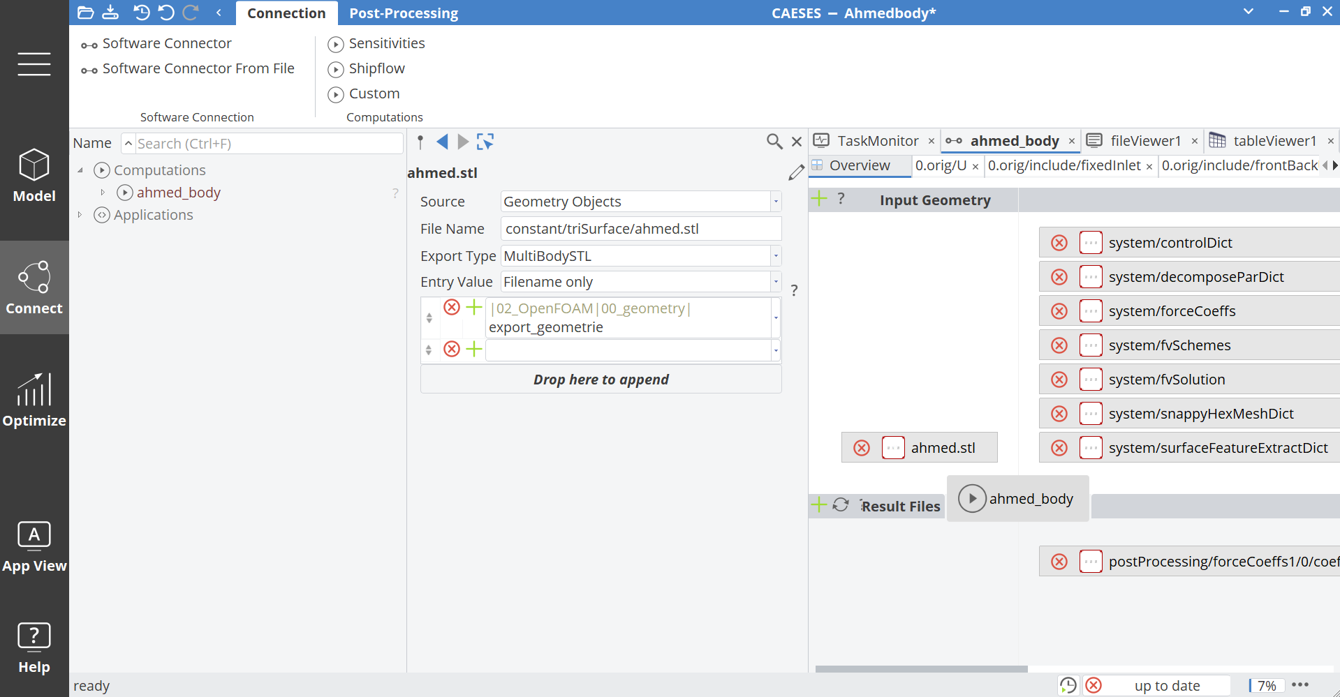
- Switch the workspace to Connect using the left navigation bar. Open the connection
ahmed_bodyvia Connect > Connection > Computations > ahmed_body. - Add an Input Geometry by clicking the plus icon in the top-left corner of the Input Geometry area.
In the automatically opening dialog, enter:
- File Name:
constant/triSurface/ahmed.stl - Export Type:
MultiBodySTL - Entry Value:
Filename only - In the empty field below Entry Value, enter:
|02_OpenFOAM|00_geometry|export_geometry
Simulation Parameters
In this step, certain OpenFOAM simulation parameters are linked to CAESES parameters.
Step 1: Create New Entry in Configurations
- Switch to the Connect workspace.
- Open the
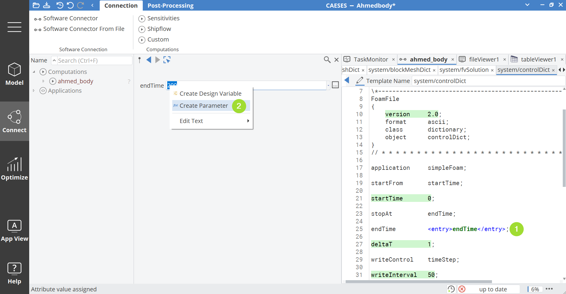
ahmed_bodyconnection and double-click the filesystem/controlDict. - Select the line containing
endTime(highlighted in green).
A new Entry is automatically created in the configuration tree on the left.
Step 2: Create a Parameter from the Entry
- Highlight the value (e.g.,
60). - Right-click and choose Create Parameter.
- Rename the parameter to
endTime.
Repeat Step 1 and Step 2
Repeat this process for all parameters listed below:
| Entry Name | OpenFOAM File | Line | Parameter Name |
|---|---|---|---|
flowVelocity | 0.orig/include/initialConditions | 9 | flowVelocity |
nu_air | constant/transportProperties | 19 | nu_air |
magUInf | system/forceCoeffs | 27 | magUInf |
IRef | system/forceCoeffs | 28 | IRef |
Aref | system/forceCoeffs | 29 | Aref |
numberOfSubdomains | system/decomposeParDict | 17 | nProcs |
nProcs | Allrun.sh | 13 | nProcs |
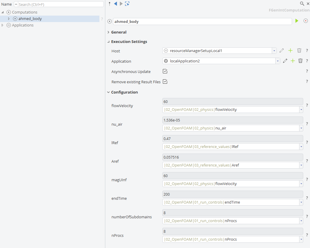
Organizing Parameters
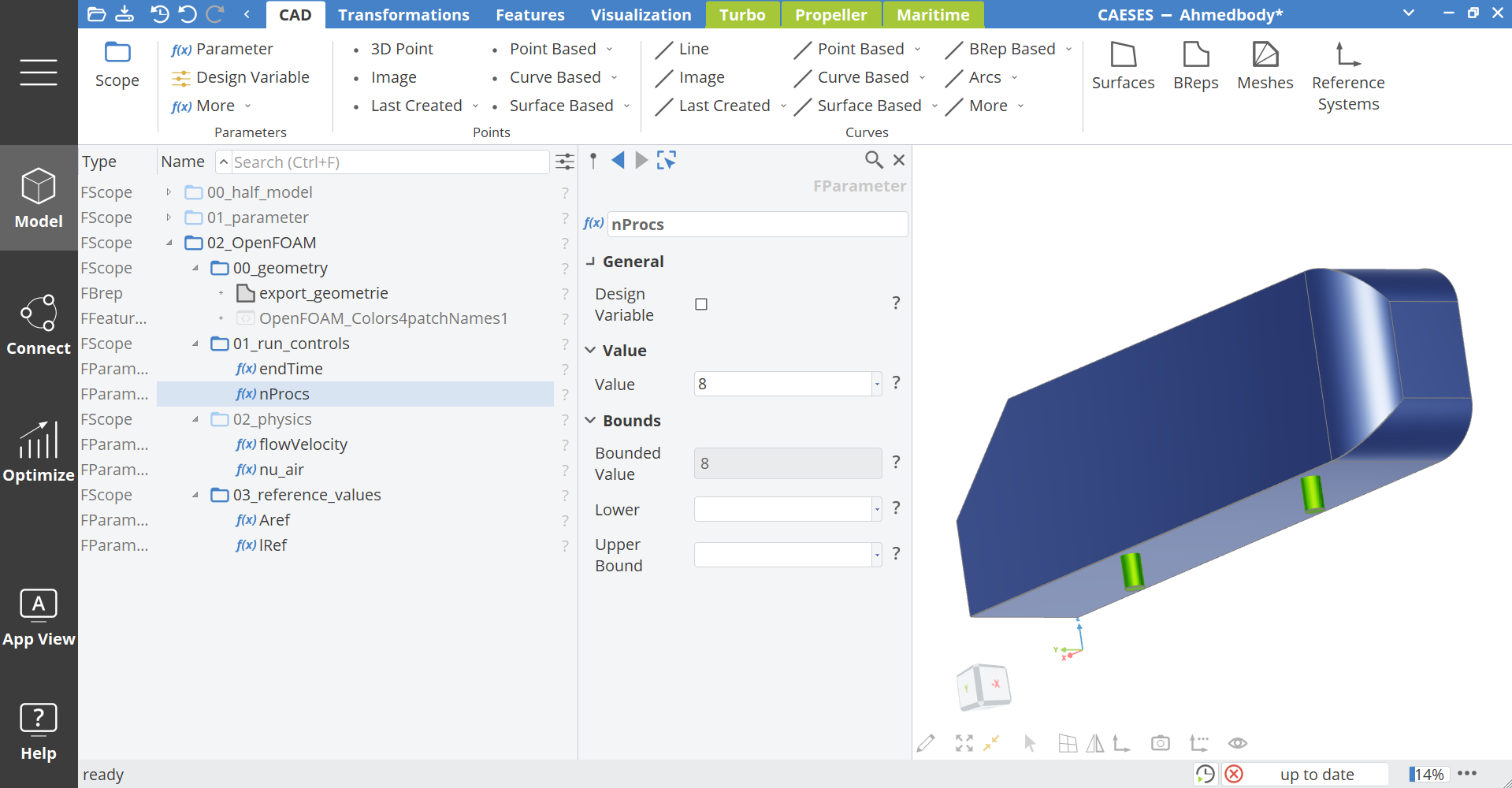
To keep the parameters structured, create scopes inside 02_OpenFOAM:
- Create a new scope inside
02_OpenFOAMvia Model > CAD > Scope and set the name to01_run_controls. - Drag and drop the parameters
endTimeandnProcsinto this scope. - Create a new scope inside
02_OpenFOAMvia Model > CAD > Scope and set the name to02_physics. - Drag and drop the parameters
flowVelocityandnu_airinto this scope. - Create a new scope inside
02_OpenFOAMvia Model > CAD > Scope and set the name to03_reference_values. - Drag and drop the parameters
ArefandlRefinto this scope.
OpenFOAM Environment Setup
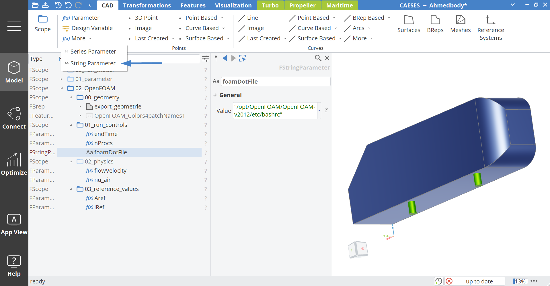
The OpenFOAM environment is defined in the Allrun.sh script. Here, the path to the OpenFOAM bash script must be specified.
- Create in the scope
01_run_controlsa String Parameter via Model > CAD > More > String Parameter. - Name it:
foamDotFileand fill in your path to the OpenFOAM bash script (for example:"/opt/OpenFOAM/OpenFOAM-v2012/etc/bashrc"). - Open the
Allrun.shscript and highlight the path behind thesourcecommand (line 6). - Right-click the highlighted string and choose New Entry.
- Double-click the newly created entry, rename it to
OFPath. - In the value field, enter:
|02_OpenFOAM|01_run_controls|foamDotFile. - Store this string parameter inside the scope
02_OpenFOAM|01_run_controls.
This links the CAESES parameter directly to the OpenFOAM environment path.
Post-Processing
Simulation results (e.g., force coefficients) can be made accessible inside CAESES.
- Switch the workspace to Connect and open the
ahmed_bodycomputation via Connect > Connection > Computation > ahmed_body. - To store it in the folder structure of OpenFOAM, double-click on the file
coefficient.datin the Result Values area. - Change the subfolder via General > Subfolder to:
postProcessing/forceCoeffs1/0/.
To read the last column of this file:
- Click the plus icon in Values next to the entry Name.
Set the following arguments:
- Change the entry Name to
Cd. - Line:
212. - Column:
1.
To create a parameter from the result coefficient:
- Click the parameter icon f(x) in the Results Preview.
- Change the name of the parameter to
Cd.
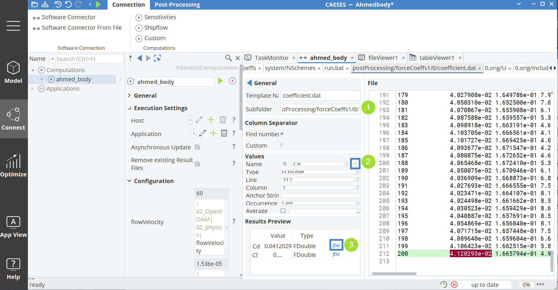
To also read the lift coefficient, create another result value with:
- Name:
Cl. - Line:
212. - Column:
3. - Click the parameter icon f(x).
- Change the name of the parameter to
Cl.
Both result parameters should be stored in a scope:
- Create a new scope via Model > CAD > Scope and set the name to
04_resultsinside the scope02_OpenFOAM. - Drag and drop the parameters
CdandClinside this scope.
Run Simulation
In this step, the simulation is triggered:
- Open the computation
ahmed_bodyvia Connect > Connection > Computation > ahmed_body. - Click the green play icon next to the name entry.
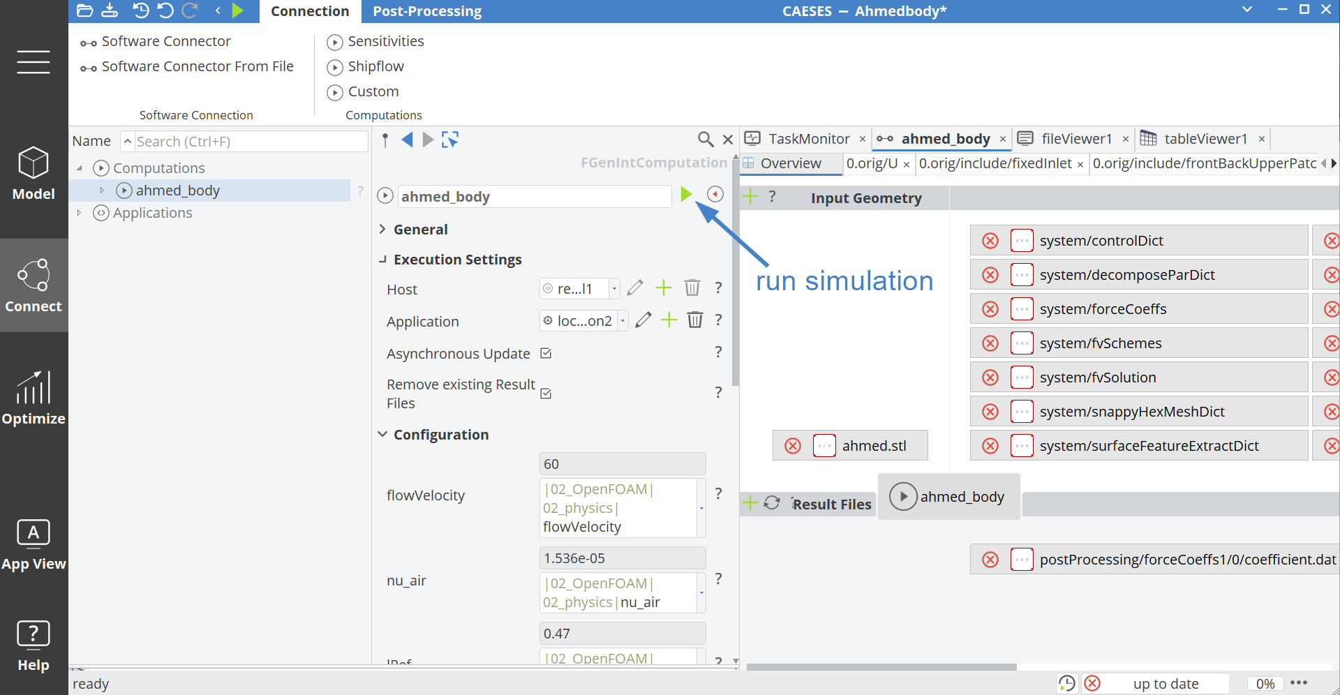
Visualization
To show the pressure or velocity field:
- Open in the Connect workspace the Post-Processing via Connect > Post-Processing > Results > ahmed_body > internalMesh.
- Select from the drop-down menu in the Visualization settings
create new.
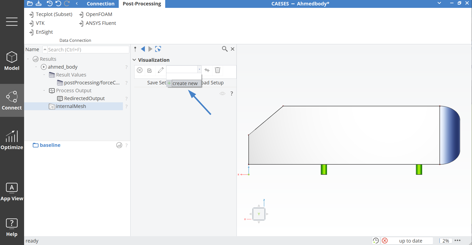
- In Data Extraction click on
FGridPlaneCut.
In the GridPlaneCut1 settings:
-
Position:
0.01. -
Plane:
Y-(Z,X). -
Click in the Visualization field in the empty entry and select from the drop-down menu
create new.
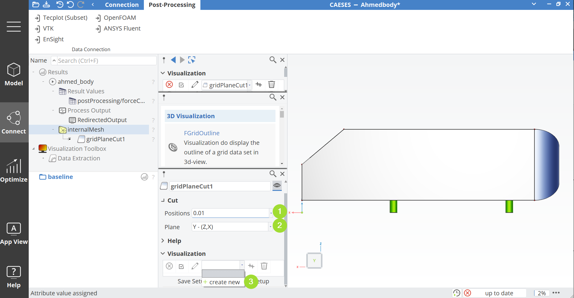
- Select
FContourPlot. - In
contourPlot1set the Mapped Data to[U].
In the 3D view the velocity field should now be displayed. If you want to see the pressure field, select p for Mapped Data. To hide or show the data in the 3D view:
- Click on the icon next to internalMesh.
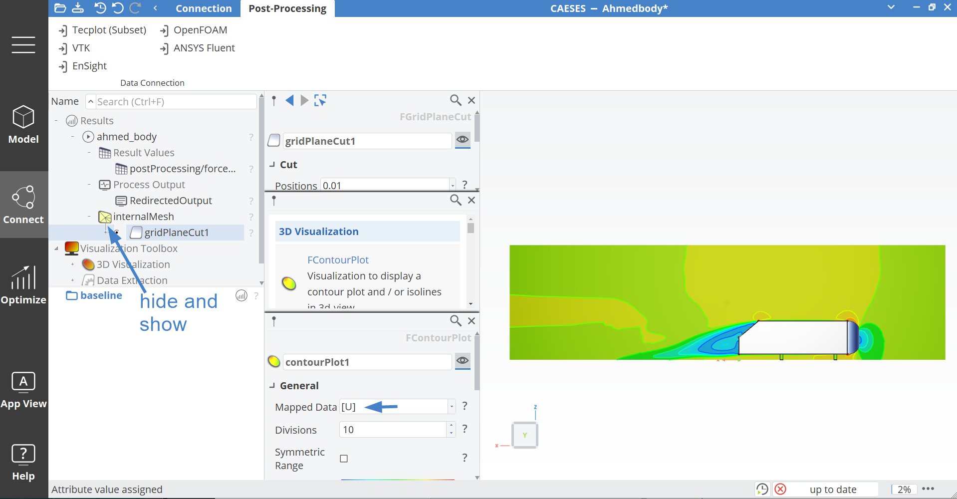
CAESES Project File
If you want to take a look at the finalized model, you can find the resulting CAESES project file ahmed-body-open-foam.cdb here:
Load Final Model