STAR-CCM+ Connection
The purpose of this tutorial is to learn the connection to a 3rd party CFD software, in this case STAR-CCM+. You will use an existing duct geometry, prepare it for the export and connect it with STAR-CCM+.
The CFD setup in STAR-CCM+ is created in batch mode with JAVA macros. These macros can be recorded in STAR-CCM+ and modified with e.g. NetBeans (or any other IDE of your choice).
Options to couple CAESES with STAR-CCM+
To control STAR-CCM+ in batch mode it is necessary to write or record java macros, which have to be included in the software connector of CAESES. The following flowchart shows the two ways of coupling STAR-CCM+ with CAESES.
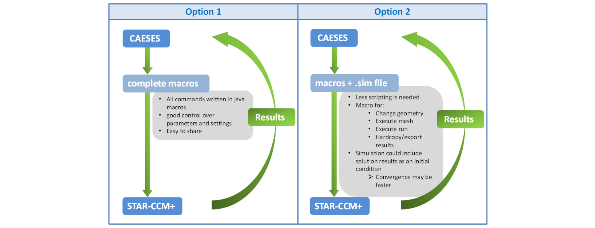
One way is creating the complete setup with java macros. To achieve this you have to record the macros in STAR-CCM+, while setting up the complete case. This could be difficult in very complex cases. That's why another option of coupling STAR-CCM+ to CAESES is to set up the whole case in STAR-CCM+ without recording macros. When the case is completed, you only have to record or create macros which change the geometry, create the mesh, start the simulation and export the results.
In the software connector you have to provide the macro files and the simulation file. Another advantage of this way is that you could have a solution in the simulation file. This solution can be used as an initial condition hence the simulation will converge faster.
In this tutorial we explain option 1 with complete macros.
Model Preparation
For this tutorial we use the model from the tutorial Introduction to Meta Surfaces:
Download ModelIn order to get a closed fluid volume, we need to close the inlet and outlet of the duct. Furthermore we extend the duct for a more realistic flow solution.
- Select the surface ductSurface in the scope 02_duct.
- Create a BRep via Model > CAD > BReps > BRep and set the name to "ductClosed".
- Click on the edit button right of the first operation
- Set the color ductWall to this operation. This color was already created in the tutorial First Modeling Steps.
- Create a new operation via add new operation > Extrusion > Extension from Open Loop. For this operation set the following:
- Set the Extrusion Distance to
300. - Set the Extrusion Direction to
[-1,0,0]. - Set the Color of Extrusion to ductWall.
- Set the toggle Close Extrusion to active.
- Set the Color of Closing to *ductInlet.
- Set the Extrusion Distance to
- Create a new operation via add new operation > Extrusion > Extension from Open Loop. For this operation set the following:
- Set the Extrusion Distance to
300. - Set the Extrusion Direction to
[0,1,0]. - Set the Color of Extrusion to ductWall.
- Set the toggle Close Extrusion to active.
- Set the Color of Closing to ductOutlet.
- Set the Extrusion Distance to
Finally we need to set the correct project units.
- Go to Model > File and select the project object in the tree:
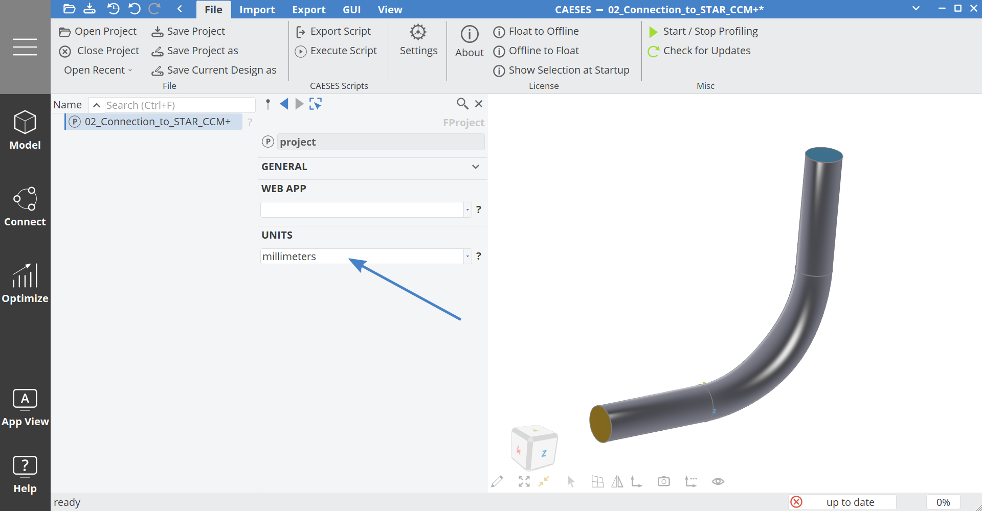
- Set the Units to millimeters.
Software Connection
At this point we can start by connecting STAR-CCM+ to CAESES. We use a so called Software Connector for this.
- Go to Connect > Connection.
- Create a new Software Connector via Connect > Connection > Software Connection > Software Connector.
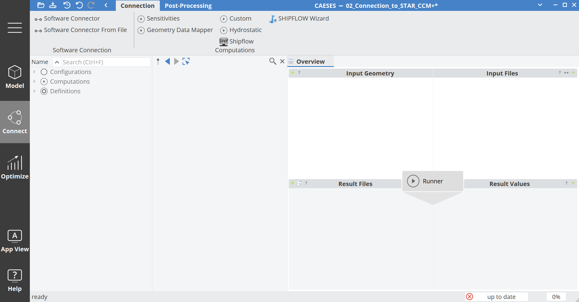
Input Geometry
Let's start configuring the Software Connector by defining our Input Geometry for simulation.
We can use the Search field above of the Object Tree to find your prepared geometry.
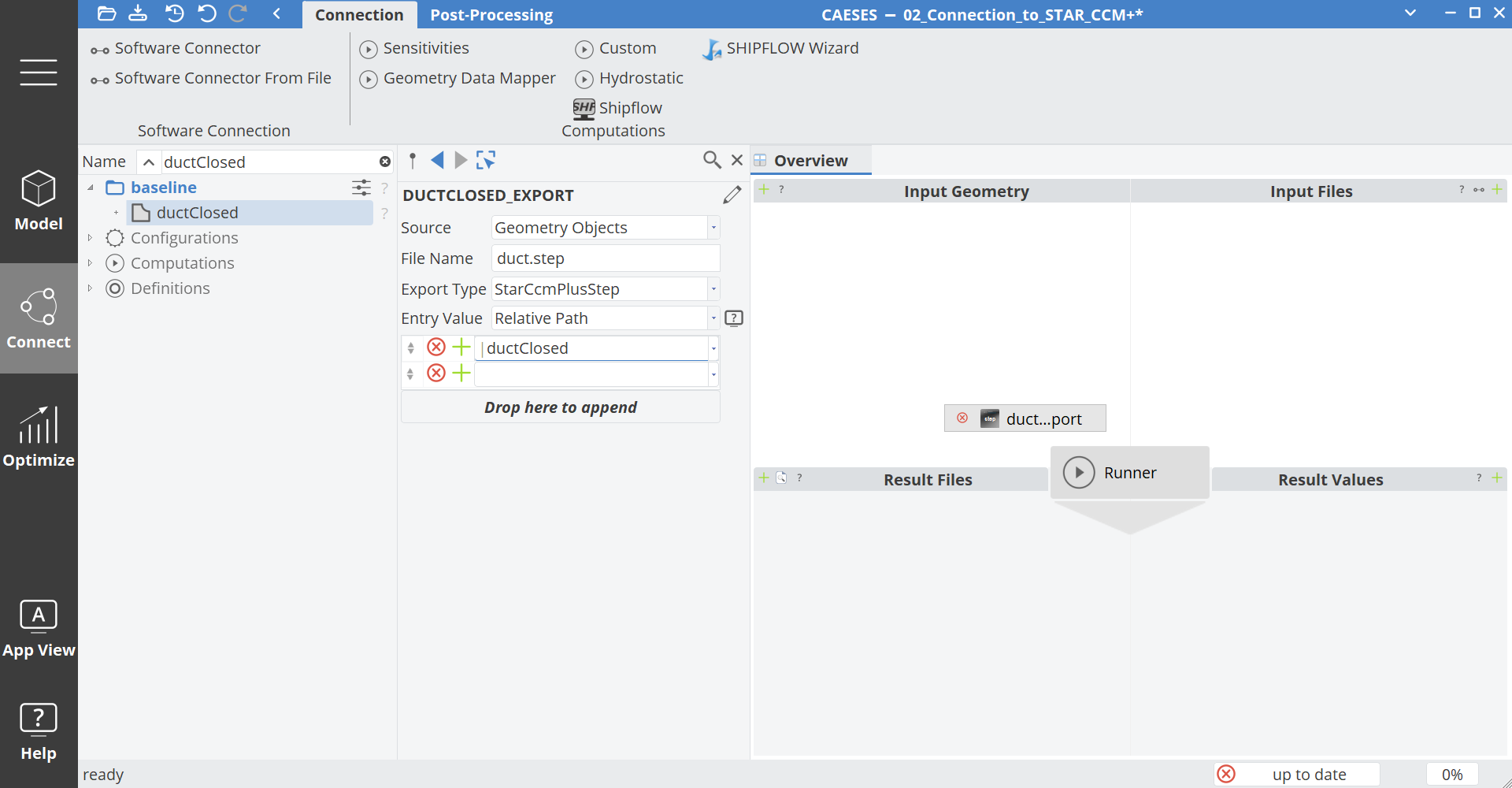
- Above the Object Tree enter "ductClosed" in the Search field and expand the tree results with the Enter key.
- Drag and drop the BRep ductClosed to the area of the Input Geometry of the Software Connector.
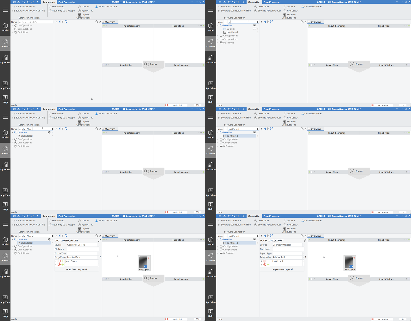
You will see the properties of this input geometry in the Object Editor.
- Set the File Name to "duct.step"
- Set the Export Type to StarCcmPlusStep
- Right click anywhere in the Software Connector and set the view to small
Input Files
In this area of the Software Connector we define the files to setup and control the simulation software. In this example we use java macros to setup the simulation for STAR-CCM+.
-
Download the
Download setup.javasetup.javafile -
Click on the + button next to Input Files.
-
Navigate to the file
setup.javaand add it to the Input Files field.

- Activate the toggle Convert to Template. This will save the file inside the project. Otherwise a reference to the file will be used.
If you have large or binary files, you should not use the option Convert to Template since your project size may get very large and your binary files cannot be modified.
- Click on add so that the file is added to the Software Connector.
- Double click on setup.java in order to see and modify the input.
If the file was not imported with the option Convert to Template, then a double click on the file would also convert it to a template.
- Scroll down the file and look for the line
stepStoppingCriterion_0.setMaximumNumberSteps(600);in line140.
By default this line is highlighted in green. This mode is called assisted mode: it will look for numbers which the user might want to change. You could also deactivate the assisted mode with a click on the edit button on the top left of the editor.
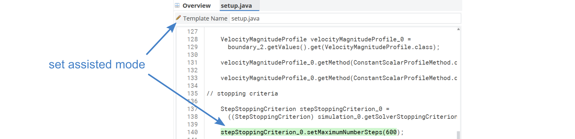
- Click on the green highlighted area to create a new entry.
In the Object Editor you will find this new entry.
- Click on the name of the entry in order to edit the entry settings.
- Set the name to "iterations".
- Set the type to FUnsigned.
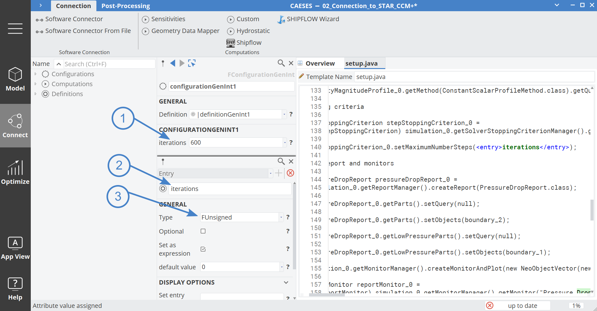
We could also define mesh size or inlet velocity, but for demonstration purposes, this is enough.
- Go back to the overview with a click on the Overview tab at the top of the Software Connector.
Result Files
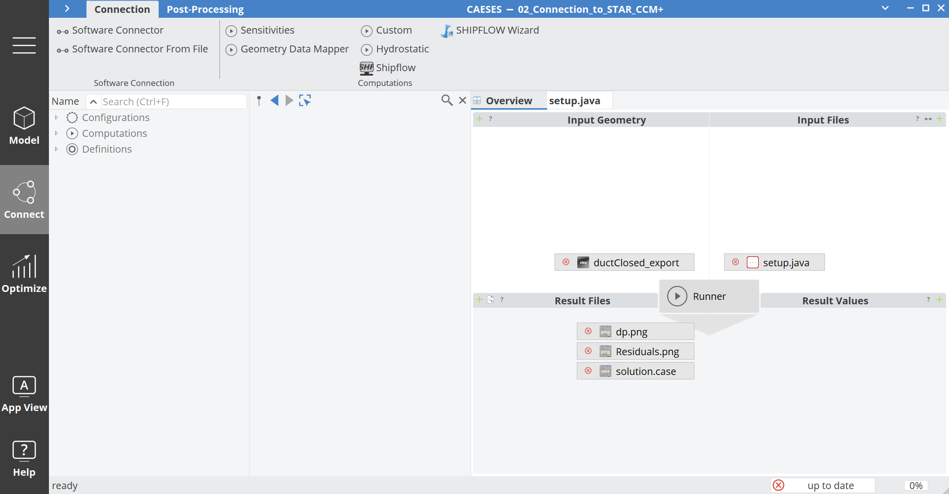
In this area of the Software Connector we define the result files of the computation. These can be images, tables and solution files for post-processing.
- Download the example
*.pngfiles, as well as thesolution.casefile.
Download dp.png Download Residuals.png Download solution.case
- Click on the plus button next to Result Files and add the files:
dp.png,Residuals.pngandsolution.case.
The file solution.case is an EnSight Gold file, which is typically used to exchange flow results between STAR-CCM+ and CAESES.
Result Values
This area of the Software Connector is used to extract values from result files. In this example we are loading output file of the pressure drop. From this file we want to extract the pressure value from an average of the last iterations.
- Download the example csv file and add it to the Software Connector.
- Click on the plus button next to Result Values and choose the
dp.csvfile. - Double click on the file
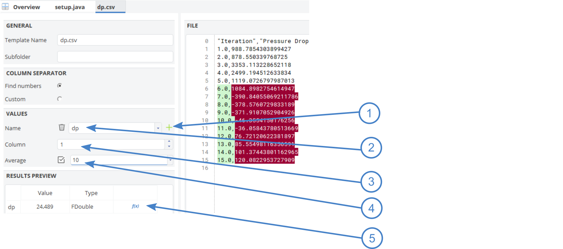
dp.csvin the Results Values area of the Software Connector. - Click on the + button to add a new entry.
- Set the name of the entry to "dp".
- Set the Column to
1. - Activate the toggle Average and set the value to
10. - Click on the Parameter icon to create an evaluation parameter.
- Go back to the overview with a click on the Overview tab at the top of the Software Connector.
Computation Settings
The last part of the software connection is to define settings of the computation.
- Click on the Runner button in the middle of the Software Connector.
- Click on the + button next to Local Application.
- Set the path to the executable of STAR-CCM+.
- Set the Maximum Number of Running Instances to
1. This means that only one STAR-CCM+ computation is allowed at the same time. If your computer resources and licenses allows to run more computation next to each other, you can increase this value.

Now we need to give some arguments to the executable to specify: batch mode, number of processors, license, macro.
-
Set the Arguments of the runner depending of your license type to:
"-batch setup.java -rsh ssh -np 2 -power -podkey xxx -licpath 1999@flex.cd-adapco.com -new"
If you use the Power on Demand license option, as we do, replace the xxx with your license key. If you use a different license type, you may have to adjust the arguments.
- Start the computation with a click on the green play icon on the top of the Runner or in the blue title bar.
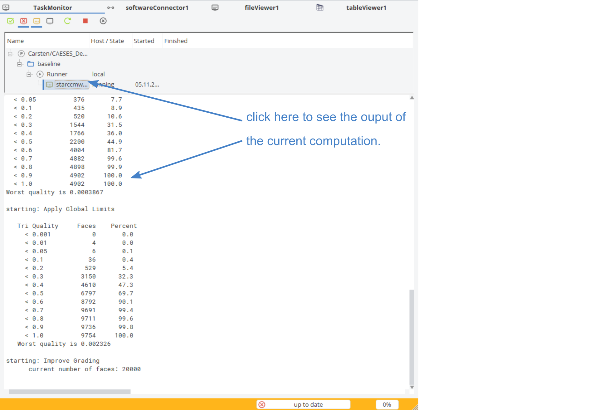
You can monitor the progress with the Task Monitor.
- If it is not already shown, then you can open it with a right click on the blue title bar and select the Task Monitor.
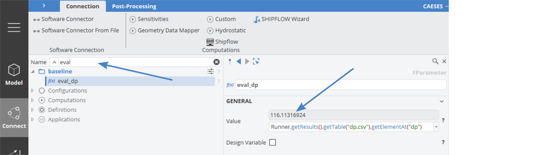
- After the computation has finished you can check if you evaluation parameter eval_dp has some value. We can use the search functionality for this again:
Post-Processing
Now we can visualize a simple contour plot of the velocity inside the duct.
- Go to the tab Connect > Post-Processing.
- In the 3D View activate all geometry filters, in order to hide all objects.

- Expand the Results node in the Object Tree until you see the Region of solution.case:

Plane Cut
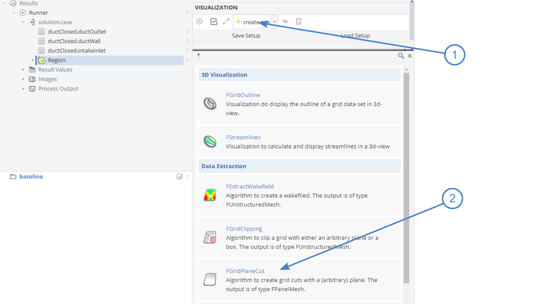
- Select Region in the Object Tree.
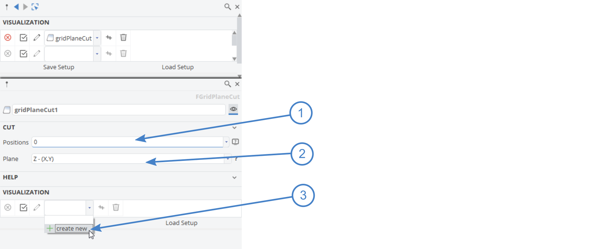
- Choose Create New in the drop down menu.
- Click on FGridPlaneCut to create a new cut, which can be used to visualize solution data.
- Set the Position to
0. - Set the Plane Z-(X,Y).
Contour Plot
- Click on Create New in the drop down menu of Visualization and select FContourPlot.
- In Mapped Data choose Velocity Magnitude.
- Set the Divisions to
20. - Set Preset to Colored Surface.
- Finally click on the Z face of the cube to move to the Z-plane and zoom in.
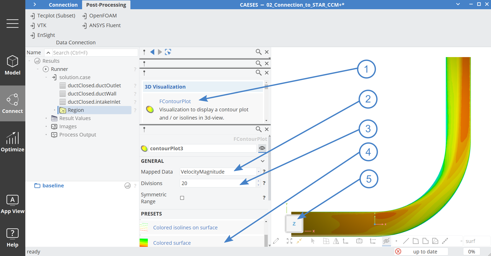
Note, that the results are imported with the units Meter, that is why you can not see the geometry and the results at the same time. You could create an image of the geometry and scale it down by 1/1000 in order to see geometry and results in the same view.
Color Map
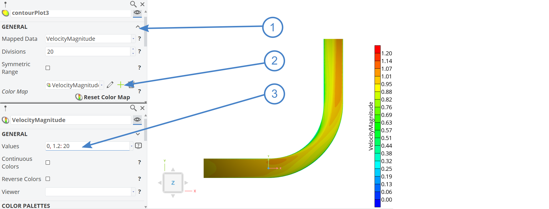
At this point we will create a new Color Map with a fixed velocity scale. This is important to compare different designs afterwards.
- In the contour plot click on General to expand the editor
- Click on the + button next to Color Map.
- Set value to:
0,1.2:20. - You can also play with different Color Palettes, orientation and location.
Geometry Study
Finally we at the point to set up a design study.
- Go to the workspace Optimize > Optimization.
- Create a new Sobol Design Engine via Optimize > Optimization > Design Exploration > Sobol.
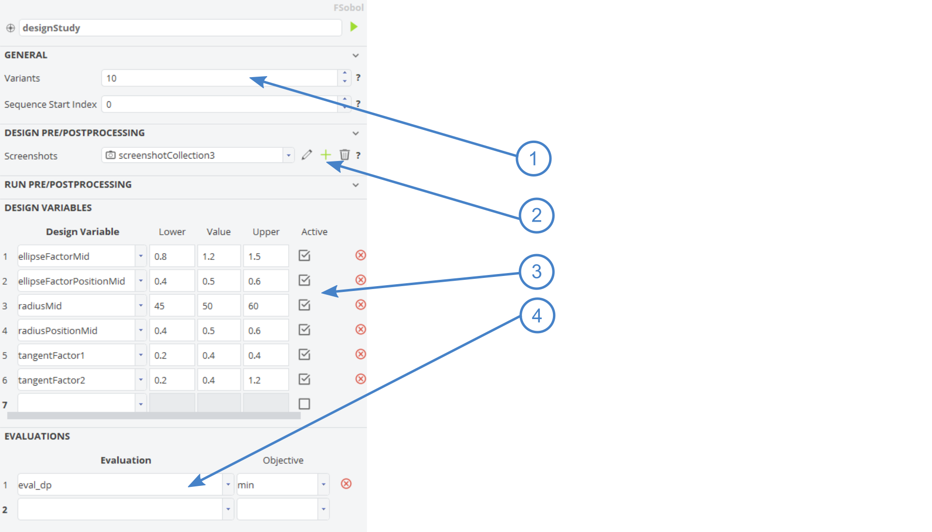
- Set the name to "designStudy".
- Set the number of Variants to
10. - Create a new Screenshot Collection.
- Set all available Design Variables; the default bounds are fine.
- Add the Evaluation Parameter eval_dp. And make sure that the Objective is set to min. The Sobol engine will not minimize, but the best designs are marked afterwards in blue.
- Click on the green play button to start the design study.
While the design engine is running you can check again the computations in the Task Monitor.
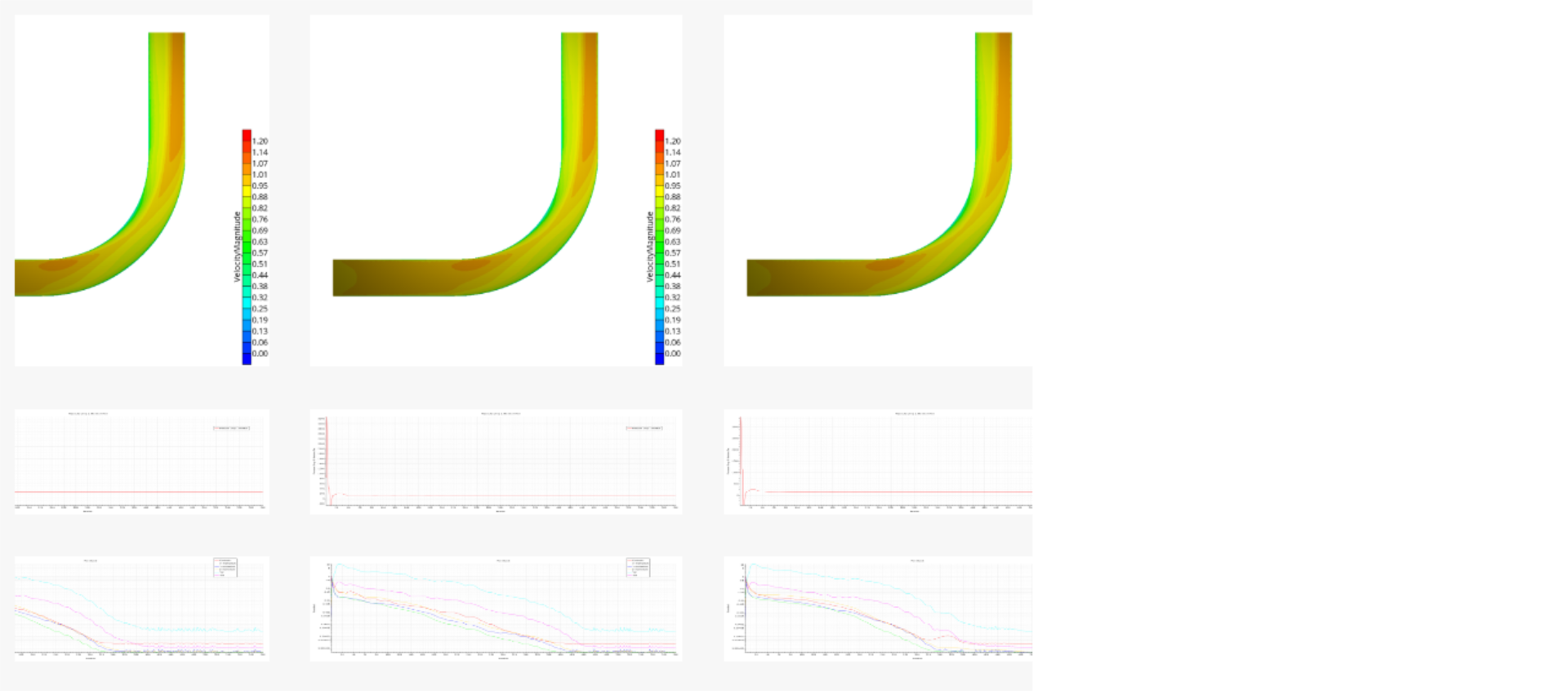
After the computations have been finished, you can compare the designs for example in the Design Viewer:
CAESES Project File
If you want to take a look at the finalized parametric model you can find the resulting CAESES project file connection-to-STAR-CCM+.cdb here: