Creating a Feature
Feature instances (i.e. objects of your feature in the object tree) are based on so-called feature definitions. In the first step you need to create such a definition. Basically, this definition holds the information about the input arguments, the command sequence and the resulting objects.
Create a New Feature Definition
In order to create a new feature definition, go to the Model workspace and choose the Features Tab
- Model > Features > Create Definition
from the CAESES ribbon. A new definition will appear in the object tree in the tab Features in the Model workspace.
There is a difference between Feature (instance in the CAD tab tree) vs. Feature Definition (in the Features tab tree)
General Tab
Once you have created the definition, the general tab is the first thing you see.

Type Name
Specify a type name for your feature definition. This is the type for upcoming instances.
Feature Label
Labels are an optional setting. They will appear in the menu if you include features in the GUI, which will be discussed later.
Save and Load
The definition is only stored in your project. If you want to re-use it, you can export it and drag & drop it into new projects. Next to the type name, you find icons to save the definition on your hard drive.
The default location of saved features is your user directory that is also listed in the main CAESES menu (Model > Features > store > user directory) so that they show up here. You can organize this directory yourself, e.g. create own folders with meaningful names. This structure is then shown according to your structure in this feature menu. If you want to include more directories and not only your user directory, add custom directories via the CAESES menu Menu > Settings > features.
There is also an icon to load an existing feature definition which you can use to e.g. update your definition with a newer or different version.
Documentation
When you click on the "Add/Edit Documentation" icon, you can add your own user documentation to the definition. When creating a feature from this definition, this documentation will show up.
Options
Save Protection
If this is enabled, a warning will be issued when trying to change the Feature Definition
Enable Persistent / Enable Transient
Features can be executed in two ways:
- Persistent creation means that the Feature Definition defines a custom type.
- Transient execution means that the Feature Definition behaves similar to a macro, i.e. it defines a series of commands that is executed.
Is Drawable
If the Feature Definition is set to "Enable Persistent" toggling this box means that Features based on this definition will be rendered into the 3D-View. A feature is drawn by drawing all elements (attributes) of the feature that can be drawn.
Update Only On User Request
If this is enabled, Features based on this Feature Definition will only be updated if the user manually presses the button from the main toolbar or the Feature's context menu.
Feature Definitions Tab
In this tab, you can include other feature definitions of CAESES if needed (see the chapter "Nested Features"). You can access your own stored definitions from here, to reuse and to nest them into the current definition. In order to use nested definitions, you need to write a "feature persistent" command such as fp_myFeature name(1,2,3) in the "Create Function" tab, where (1,2,3) are the arguments of the feature, e.g. simple numbers. This nested feature functionality is a rather advanced but very helpful option for efficient work.

Arguments Tab
Arguments are the variable part of your definition. This is the user input which you include in your code sequence. Arguments can be accessed from the "Create Function" which defines the Feature's programming logic.

Type
This is the type of the Argument. Only objects that match that type can be passed as that argument. The most common types are FDouble, FUnsigned, FVector3, FObjectList. However, you can work with any type of CAESES, also exotic ones such as cameras, results, design engines, transformations, files etc.
If you want to use vector data e.g. from 3D points, you should always go for the most basic type. In this case, instead of choosing F3DPoint as input argument, it is recommended to go for FVector3 since this is more generalized and allows also other point types (projection points, intersection points etc.) to be used. Note that then also simple vector data (e.g. an expression with a vector return value, e.g. [0,0,0]) could also be input, which gives you more flexibility. Other candidates are FCurve and FSurface (instead of derived types such as FLine or FBSplineSurface).
Name
This is the variable name that you can then use in the "Create Function" tab.
You can always change this name, also at a later stage. CAESES automatically changes all occurrences in the code.
Default Value
This value is automatically set when creating a new instance of the feature.
Allow Expression
Set this to true to allow expressions as input for your argument. If you set it to false, you can only set objects with the exact matching type or only discrete values.
Required
If true, it forces the user to set the input argument. Otherwise, the feature will not update. If this is checked, the argument will be marked with a red asterisk in the Feature's object editor until it is filled with a valid value.
Category
Helps to structure the user interface of the feature object, and allows you to group together arguments.
Argument Label
This is the label that appears in the feature user interface. It can be different from the "Name" to make it more readable for the user.
Advanced
Pressing the Advanced button allows to enter advanced settings for an argument. This also includes the argument's documentation that is shown when clicking the question mark (?) next to each argument field in the feature instance.
The advanced options of an argument allow to create dynamic behavior of the Feature's object editor and to customize the appearance of the object editor, by adding buttons that trigger commands, for example.
Advanced Argument Settings
Description
Each argument can have its individual documentation. This input field allows to edit that documentation. This documentation is displayed next to each input argument when clicking the question mark symbol (?).
Weight
This field determines the position of an argument in the Object Editor within its category. A high weight value will cause the argument to move to the bottom, a low value will cause the argument to move to the top. The default value for all arguments is 100.
Show Always
If this option is toggled (default), the argument will always be shown in the object editor. By unchecking this box, the argument will be placed in the "more options" of its category, which is shown when expanding a category by clicking its header.
Refreshes Editor
If this option is set, a change of the value of this argument will cause a refresh of the Object Editor. This is necessary, if dynamic content of the Object Editor depends on this argument.
Is Hidden
If this checkbox is toggled, the argument will not be shown in the Object Editor. It can, however, be used inside the create function and in the conditions that determine dynamic content of the Object Editor.
Is Hidden Condition
This is one of the conditions for dynamic content of the Object Editor. It allows to hide an argument when certain conditions are met, e.g. when another argument has a certain value. If the condition depends on another argument of the Feature Definition, that argument needs to have the "Refreshes Editor" option checked. The value of the condition needs to be a command that is of type FBool (i.e. evaluates to true or false).
Is Editor Hidden Condition
This is one of the conditions for dynamic content of the Object Editor. It allows to hide the editor of an argument when certain conditions are met. The argument row including its label, checkboxes (if configured) and buttons (if configured) will still be displayed.If the condition depends on another argument of the Feature Definition, that argument needs to have the "Refreshes Editor" option checked. The value of the condition needs to be a command that is of type FBool (i.e. evaluates to true or false).
Is Enabled Condition
This is one of the conditions for dynamic content of the Object Editor. It allows to disable the editor of an argument when certain conditions are met. Any Checkboxes (if configured) and buttons (if configured) will stay active. The value of the condition needs to be a command that evaluates to bool (i.e. true or false).
Is Checkable
If this is set, a checkbox will be inserted in front of the argument's editor. The behavior of the checkbox can be configured using the following settings.
Toggle On Action
If the "Is Checkable" option is set, this setting determines the command or series of commands that will be executed when the checkbox is checked, i.e. when clicking on it while it is in the unchecked state. Multiple commands can be entered by separating them using ;.
Toggle Off Action
If the "Is Checkable" option is set, this setting determines the command or series of commands that will be executed when the checkbox is unchecked, i.e. when clicking on it while it is in the checked state. Multiple commands can be entered by separating them using ;.
Is Toggled Condition
If the "Is Checkable" option is set, this setting determines whether the checkbox is displayed in the checked or in the unchecked state. The value of the condition needs to be a command that is of type FBool (i.e. evaluates to true or false).
Checkbox Enabled Condition
If the "Is Checkable" option is set, this setting determines whether the checkbox is enabled, i.e. whether its state can be changed. The value of the condition needs to be a command that is of type FBool (i.e. evaluates to true or false).
Checkbox Tooltip
If the "Is Checkable" option is set, the string that is set here will be displayed as a tooltip when hovering over the checkbox with the mouse.
Checkbox Refreshes Editor
If this option is set, clicking the checkbox will cause the Object Editor to be reloaded. This is necessary, if dynamic content of the Object Editor depends on the state of the checkbox.
Exported to XML
If an instance of this Feature is used inside a custom definition, this determines whether the argument is written into the exported XML file.
On Value Change Action
Commands that are set here will be executed when the value of the argument changes. Multiple commands can be separated using ;.
Buttons
This setting allows to add buttons to the Object Editor on the right side of the editor or below the editor. Pressing the "Add Button" button will create a new button.
The following table explains the options that are available for buttons.
| Button Option | Description |
|---|---|
| Text | This is the text that will be displayed on the button |
| Icon | This is the icon that will be displayed on the button. |
| Toggle On Action | If an "Is Toggled Condition" is set, this is the sequence of commands that is executed when the button goes from the state of being toggled to being untoggled. Multiple commands can be entered separated by ; |
| Toggle Off Action | This is the sequence of commands that is executed when the button is pressed. If an "Is Toggled Condition" is set, it is the sequence of commands that is executed when the button goes from the state of being untoggled to toggled. Multiple commands can be entered separated by ; |
| Is Toggled Condition | If this is set to a command of type bool, the button will be a toggle button. The current toggle state is determined by the result of the command. |
| Is Enabled Condition | This setting determines whether the button is enabled, i.e. whether it can be clicked. The value needs to be a command of type FBool. |
| Tooltip | This string will be displayed as a tooltip when hovering over the button with the mouse. |
| Prepend Linebreak | If this option is set, the button and all following buttons will be placed on a new line in the Object Editor |
| Refreshes Editor | If this option is set, pressing the button will cause the Object Editor to be reloaded. This is necessary, if dynamic content of the Object Editor depends on the commands that are executed by the button. |
Create Function
This is the place where you define your command sequences and control statements, i.e., your feature code. As mentioned before, all type and global commands can be used. The Create Function tab defines the behavior of Features based on this definition. It is programmed using the Feature Programming Language. Syntactically that language is based on the C/C++ programming language.

-
Use Auto Fix Indentation If you are within this "Create Function" window, you can choose several helpful options from the context menu (right-mouse click), in particular, the auto fix indentation option. This can be a fast and more convenient option to quickly tidy up the code while creating it.
-
Use Keyboard Shortcuts Another cool and efficient thing: if you are in a certain line (without marking anything) and then simply press Ctrl + C and Ctrl + V, it will copy and paste the current line.
Keyboard Shortcuts for the Create Function Tab
| Key Sequence | Function |
|---|---|
| Tab | When pressing tab with selected lines, all lines will be indented by two spaces. |
| Shift + Tab | With a selection, all selected lines will be outdented by two spaces |
| Ctrl + C | Copy the selected text. If no selection is made, the current line is copied |
| Ctrl + X | Cut the selected text. If no selection is made, the current line is cut. |
| Shift + Del | Deletes the selected text. If no selection is made, the current line is deleted. |
| Ctrl + V | Paste text from the clipboard. |
| Ctrl + Shift + V | Open a history of the last ten copied strings |
| Ctrl + Alt + V | Open the snippet menu. |
| Ctrl + Space | Autocomplete the current statement. If multiple possible completions are possible a list will pop up |
| Ctrl + K | Comment the selected lines. Comments the current line if no selection is made. |
| Ctrl + Shift + K | Uncomment the selected lines. Uncomments the current line if no selection is made. No effect if none of the selected lines is a comment. |
| Ctrl + F | Open the Search/Replace dialog |
| F3 | Find next occurrence of previous search |
| Ctrl + F1 | Show help for the word under the cursor (opens the Documentation Browser) |
| F9 | Toggle breakpoint in the current line |
| F5 | Start a debugging session with the current Feature code. If a debugging session is currently active, execution will continue. |
| Shift + F5 | Stops the current debugging session |
| F10 | If a debugging session is running and currently paused, will execute the next line. |
| F7 | Evaluates the Feature Definition (this also works on any other page of the Feature Definition Editor) |
| Ctrl + F7 | Applies the Feature Definition (this also works on any other page of the Feature Definition Editor) |
| Ctrl + Alt | Allows to do a column selection |
Toolbar and Help
Please note the toolbar of this window where you can find
- Code snippets
- Commenting support
- Fix indentation option
- Settings
- Code Debugger
Evaluate Button
Once you have written some commands, you can evaluate (check) your code sequence. Errors will be shown in the "Output" tab which you find right below the coding area.
Apply Button
If you press this button, the code changes are applied to all existing feature instances of this definition. So, the evaluate button checks the code and the apply button really takes over the changes and stores them at the definition.
Create Button
Use the Create button to create a feature object/instance in the CAD object tree that is based on your feature definition.
Close Button
Use this button to close the definition. Make sure all changes are applied before closing the definition.
Attributes
These are the objects that get created during the execution of your feature. All objects created within a Feature's "Create Function" tab are called Attributes.
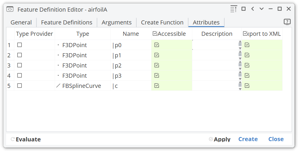
Accessible
By default, you can access all the objects from outside when the feature is created in the tree. However, in most situations you finally switch off most of these attributes to focus on the essential result of the feature. Typically, only for debugging and testing during the writing process all attributes are accessible.
Here an example if all attributes are accessible:

And another where only the curve should be accessible:

Type Provider
You can assign one of your attributes to be the type provider. This allows you to define new curve or surface objects, for instance, and seamlessly integrate them into your project.
Only one attribute can serve as type provider for the Feature. This means, that if an attribute is chosen as the type provider, this Feature can be used in any expression of that type. If, for example, an attribute of type FCurve is chosen as the type provider, an instance of this feature can be directly used in an expression that expects a curve. The actual object that is used in said expression, is the attribute that was created within the feature.
Once you activate one attribute to be the type provider, the default feature icon turns into the specific type icon - in this case, a curve icon:

Attribute Name
This is the name of the attribute. It cannot be changed from the Attributes tab, but is the name given to the attribute within the "Create Function" tab. If the attribute is set to be accessible the attribute can be accessed by that name using the : operator, e.g. myFeature:myAttribute or by the generated get command, e.g. myFeature.getmyAttribute()
Feature Creation
Finally, you create a feature object (i.e. an instance of your definition) in the CAD tree that is based on your feature definition. The fastest way to create a feature object is via the context menu (right mouse button click). Go to the Features tab and right-click the feature definition in the tree.
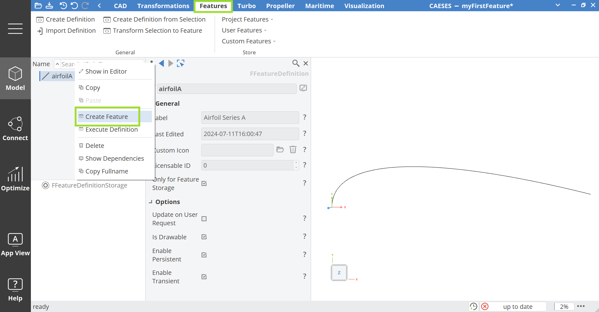
Persistent
In this context menu, you can create or execute the definition. If you choose "Create Feature", then a persistent object gets created in the object tree. You can change the input values, and the object updates itself each time something changes. This type of creation is the common choice.
Based on the previous airfoil example, this is what you would see if you create a persistent feature of it:

Transient
If you choose "Execute Definition" from the context menu, a dialog shows up and where you have to choose "Execute" again. The definition is executed once, and the result is created in the object tree. There is no feature object in the tree that still holds the entire structure. This is helpful e.g. for one-time processing tasks.

Tips for Writing a Feature Definition
Here is a recommendation for writing feature definitions, in particular when processing or creating geometries (things you can see in the 3D view):
You can create a feature from your definition even though it hasn't been finished and you are still currently editing the definition. This helps you to immediately see the effect of your modifications.
Just press the "Apply" button after you did a change (which applies it to all instances in your project) and check the results in the 3D view. Or in other words, you don't have to close and reopen the definition all the time while writing your code.
Editing Existent Definitions
In order to edit existing definitions, you can double-click on a feature definition in the object tree in the tab Features.
In addition, if you select a feature instance (not the definition) in your object tree in the CAD tab, there is an edit button in the upper right corner which allows you to quickly modify the underlying definition. Again, all instances that are based on this definition get changed by this.
