Propeller Tunnel
The Propeller Tunnel component is part of the Ship Modeling Workflow and is accessible via the Maritime tab (MaritimeThis functionality requires the Maritime add-on to be enabled.) in the Model workspace. It belongs to the modeling workflow for the ship type Hard Chine Boat. This component represents the addition of a single or a twin propeller tunnel to the hard chine hull geometry.
Model Structure
This model is divided into three main scopes:
00_parameters: Contains all Design Variables and the Parameters define the geometry of the spray rails relative to the main boat dimensions.01_geometryCurves: Contains all Curves needed for the propeller tunnel generation.02_surfaces: Contains all Surfaces needed for the propeller tunnel generation.03_brep: Contains the negative volume of the BRep This will trim the hull and will create the huill geometry with the propeller tunnel.
All design variables are located in the scope where they are first used. Their names are chosen to clearly describe their functionality, and their bounds are tested to ensure model robustness. The Hard Chine Boat workflow allows users to modify values, object types, and even the overall model structure for maximum flexibility.
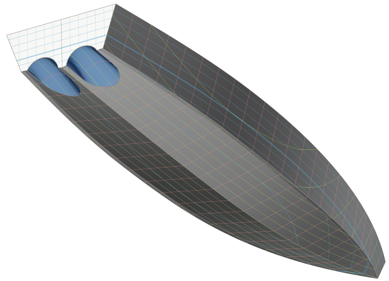
Inputs Taken from Hard Chine Boat
The following inputs are automatically taken from the Bare Hull and Hull Parameters components:
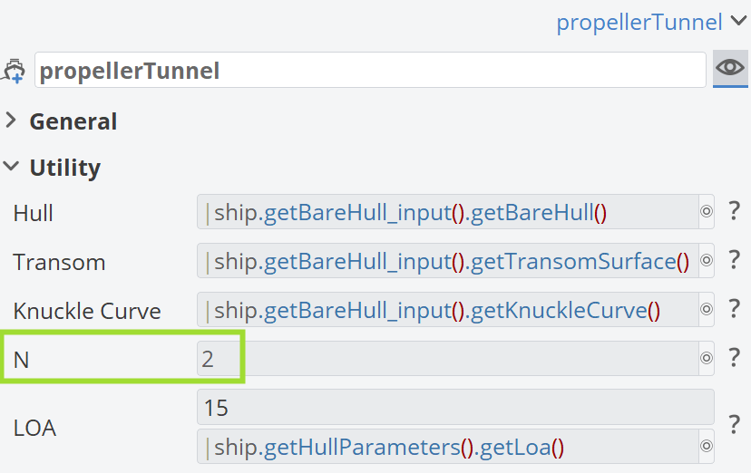
Both the Bare Hull and Hull Parameters components are required in order to create the Propeller Tunnel component.
Single or Twin Propeller Tunnel
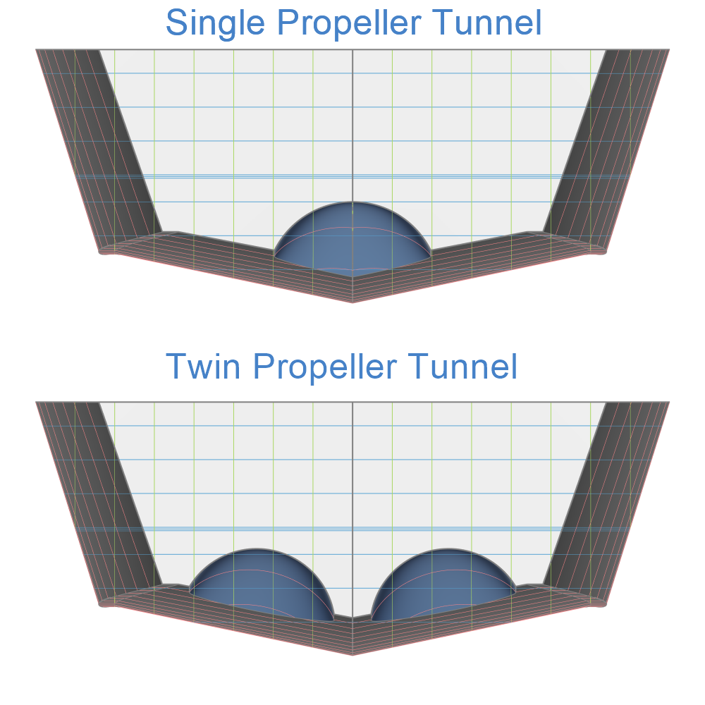
The parameter N defines the number of propeller tunnels created within the component. Two options are available during creation: a single propeller tunnel (N = 1) or twin propeller tunnels (N = 2), as shown below.
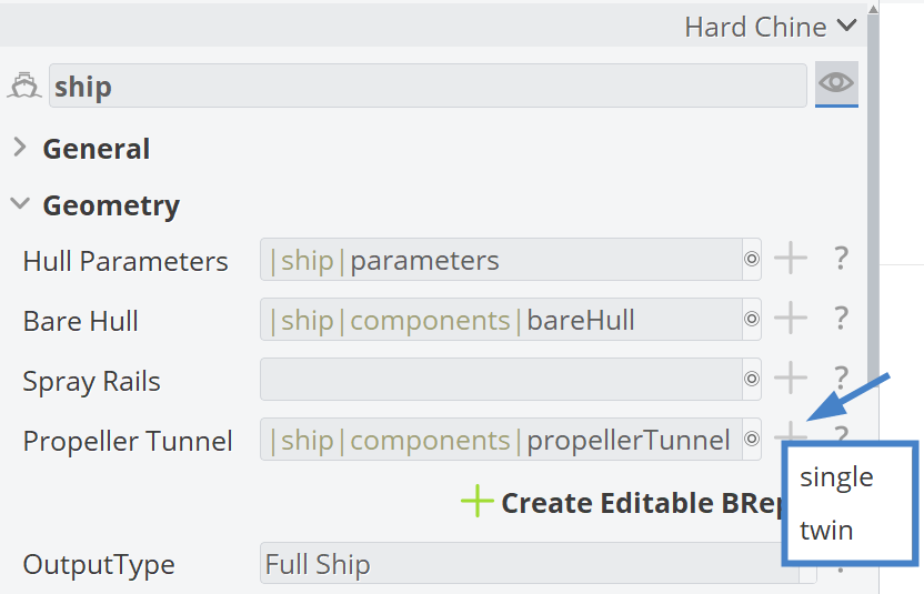
The geometric differences between these two options are illustrated below.
Parameters
The 00_parameters scope is divided into three sub-scopes:
00_absoluteDimensions01_relativeDimensions02_derivedDimensions
The Design Variables placed within these sub-scopes control the geometry of the Propeller Tunnel component and are shown below.
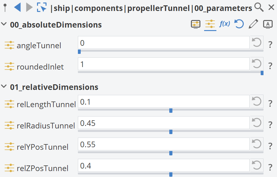
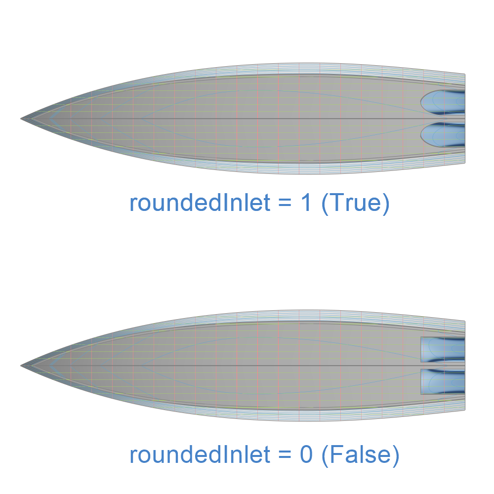
All design variables are continuous, except for roundedInlet, which is a Boolean variable taking the values True (1) or False (0). Its effect is illustrated below.
Geometry Curves
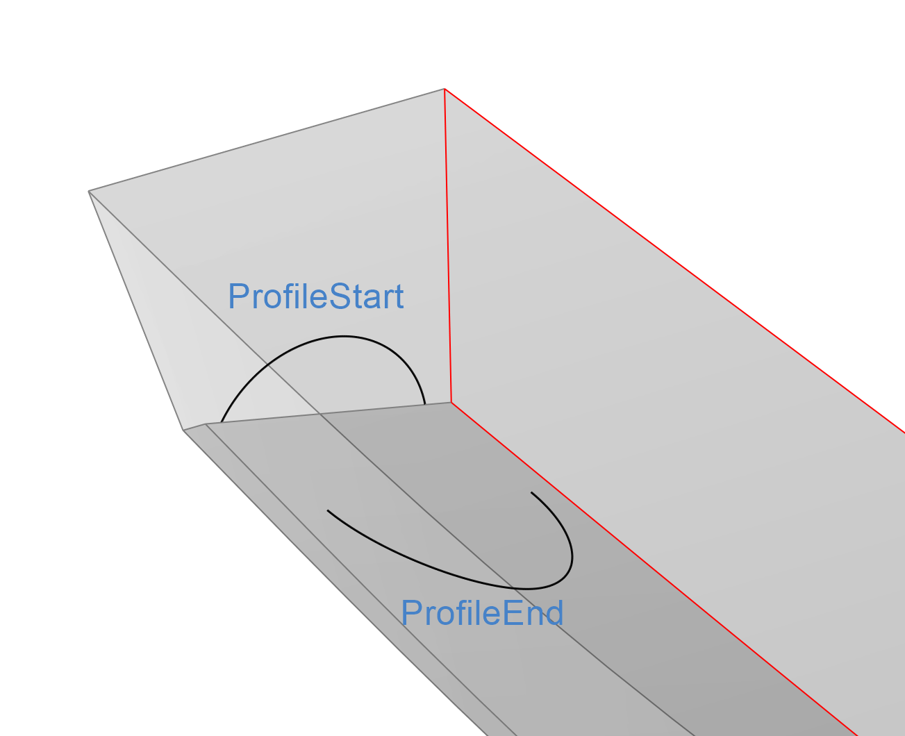
The two main Geometry Curves used for generating the negative BRep volume (later applied to trim the hull geometry) are ProfileStart and ProfileEnd. These curves lie on the transom and on the bottom of the hull, respectively.
Surfaces
The Surfaces used to generate the negative BRep volume for trimming the hull geometry are shown below. These surfaces are created using the Geometry Curves defined in the previous scope.
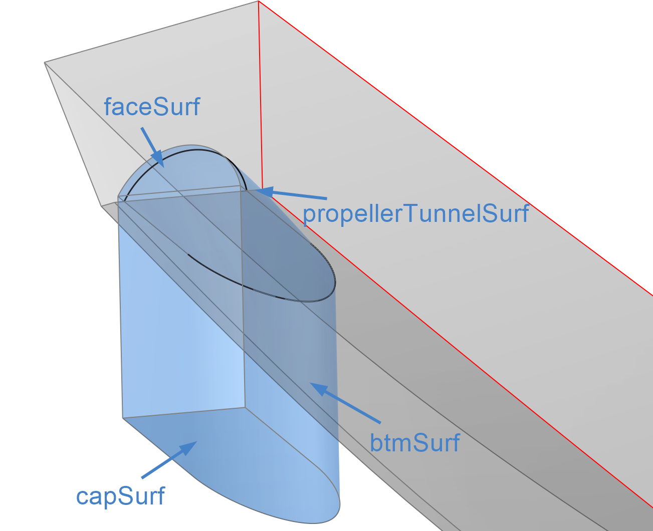
To achieve a clean cut with the hull, the surfaces are extended slightly outward from the transom and downward from the bottom of the hull.
BRep
The final negative BRep for the propeller tunnel, named tunnel_negativeVolume, can be found in the 02_brep scope. It is generated from the surfaces in the previous scope. After trimming the hard-chine hull with this BRep, the final tunnel geometry is obtained.