Hydrostatics
Hydrostatics in CAESES is linked to the Ship Modeling Workflows. It works directly on the parametric hull geometry from the Component-Based Ship or Generic Ship workflow. See also the Hydrostatics Tutorial for a step-by-step walkthrough.
Fundamentals
The fundamental principals of ship hydrostatics can be described using classical mechanics. One of the most prominent principals are Newton's laws of motions, that define a force () equal to a body's acceleration () multiplied by its mass ():
A great example of this force is the weight force of any object, resulting from the constant gravitational acceleration of the earth ( ) acting on the body's mass:
Forces in this context always consist of magnitude and direction and act on an object at an imaginary application point. The gravitational force for example points towards the earths center and acts at the body's center of mass, which is equivalent to the center of volume for homogenous bodies.
For a more complex body, the center of mass () is the point where the weighted relative positions () of all distributed masses sums up to:
Newton's first law of motions states, that a "body remains at rest, or in motion at a constant speed in a straight line, except insofar as it is acted upon by a force", which means for a floating ship, that it's weight force must have a counterpart acting in the opposite direction. So let's take a look at this opposing force!
Archimedes' Principle
The Archimedes' principle states that an object completely or partially submerged in a fluid experiences an upward buoyant force equal to the weight of the fluid displaced by the object. This principle it the key mechanic for displacement ships. In means of this documentation its defined as
where is the gravitational acceleration, the fluids density and the displaced volume of the fluid which is equal to the submerged volume of the object.
The buoyancy force acts in the opposing direction to the gravitational acceleration and has therefore a negative sign.
Equilibrium Floating Condition
Now, considering the buoyancy force () and the weight force () of a ship, we're looking at the condition, where these forces cancel each other and the sum of external forces is therefore zero. This condition is called equilibrium floating condition:
In order to have a true equilibrium, the net torque has to zero as well. For ships, this means, that the center of mass and the center of buoyancy are "above" each other, so the buoyancy force and weight force are equal in magnitude but opposite in direction.
Geometry
When we're talking about the ship, we usually only refer to the boundary representation (BRep) of its hull, which is the key element to optimize. The hull form has a direct impact on the ships hydrodynamic characteristics such as clam water resistance, bound wave system, wake and its overall efficiency. To describe a ship's hull form, several main dimensions and additional derived parameters can be utilized.
Main Dimensions
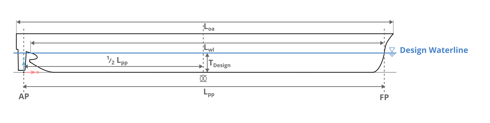
The ship's main dimensions describe the overall geometry of the hull. The following section defines all used metrics. The coordinate systems used in CAESES follows the right-hand rule with the positive x-direction pointing towards the bow, and the positive z-direction pointing upwards. In most design workflows, the origin of the coordinate system is positioned at the aft perpendicular (AP) on the keel line.
The aft perpendicular (AP) of a ship is defined with the centerline of the rudder and the forward perpendicular (FP) with the interception of design waterline and bow. The x-position of the mainframe is located at and indicated with the symbol  .
.
The design condition describes the initial floating condition of the vessel and assumes, that the boat is floating on even keel.
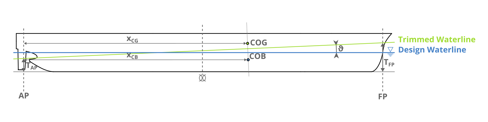
If the center of buoyancy (COB) and the center of gravity (COG) are not aligned, the vessel will pitch and roll until it reaches the equilibrium floating condition.
| Abbr. | Name | SI-unit | Description |
|---|---|---|---|
| LOA | Length overall | m | Maximum length of vessels hull |
| LPP | Length between perpendicular | m | Horizontal distance between perpendiculars |
| LWL | Length of waterline | m | Length of loaded waterline |
| Tdesign | Design Draft | m | Vessel draft on even keel in design condition |
| TA | Draft on aft perpendicular | m | Vertical distance to waterline measured at AP |
| TF | Draft on aft perpendicular | m | Vertical distance to waterline measured at FP |
| xAP | Longitudinal position of AP | m | X coordinate of aft perpendicular |
| xFP | Longitudinal position of FP | m | X coordinate of forward perpendicular |
| xMF | Longitudinal position of main frame | m | X coordinate of main frame |
| xmax | Longitudinal position of max main frame | m | X coordinate of maximum frame |
| D | Depth | m | Vertical distance from keel to top deck amidship |
| B | Beam | m | Greatest width of the vessel amidship |
| BWL | Beam of waterline | m | Maximum moulded breadth at design water line |
| Trim angle | ° | Angle between design waterline and trimmed waterline (bow down positive) | |
| Heel angle | ° | Angle around ship-fixed longitudinal axis (clockwise positive) | |
| Displacement | m³ | Displaced volume of hull | |
| Mass displaced | t | Mass of displaced fluid () | |
| S | Wetted surface area | m² | Surface area of underwater body |
| AWL | Waterplane area | m² | Area of waterplane in XY plane |
| AMF | Main frame area | m² | Area of main frame in YZ plane |
| Amax | Max frame area | m² | Maximum section area in YZ plane |
| LCB | Longitudinal center of buoyancy | m | X coordinate of center of submerged volume |
| LCF | Longitudinal center of floatation | m | X coordinate of center of waterplane area |
| IT | Transverse moment of inertia of waterplane | m⁴ | Second moment of area of the waterplane about the longitudinal axis. |
| IL | Longitudinal moment of inertia of waterplane | m⁴ | Second moment of area of the waterplane about the transverse axis. |
| BM | Transverse metacentric radius | m | Distance from center of buoyancy to transverse metacenter. |
| BML | Longitudinal metacentric radius | m | Distance from center of buoyancy to longitudinal metacenter. |
| KB | Keel to center of buoyancy | m | Vertical distance from keel to center of buoyancy. |
| KM | Keel to metacenter | m | Vertical distance from keel to transverse metacenter (KM = KB + BM). |
| Mass | Displacement mass | t | Mass of the displaced fluid (equal to ship displacement). |
| TPC | Tons per centimeter immersion | t/cm | Change in displacement per 1 cm change in draft. |
| MCT | Moment to change trim | tm/cm | Trimming moment required to change trim by 1 cm. |
Geometric Coefficients
The geometric coefficients, also known als form coefficients, aim to explain the shape of the ships underwater body in a non-dimensional fashion. They are commonly used to get a relative understanding of the hull form and are often used to compare different designs or variations of one design.
In the literature, its often not clear which exact measures are being used as reference for building coefficients. To avoid confusion, we've decided on using LPP, BWL and TMF if suitable.
Block Coefficient CB
The most commonly used coefficient is called block coefficient CB. Its the relation between displaced volume to a bounding box. The definition of the block coefficient varies in the literature and most of the time its unclear what main dimensions are being used to describe the referenced bounding box. Within CAESES, we define the block coefficient with:

Mainframe Coefficient CM
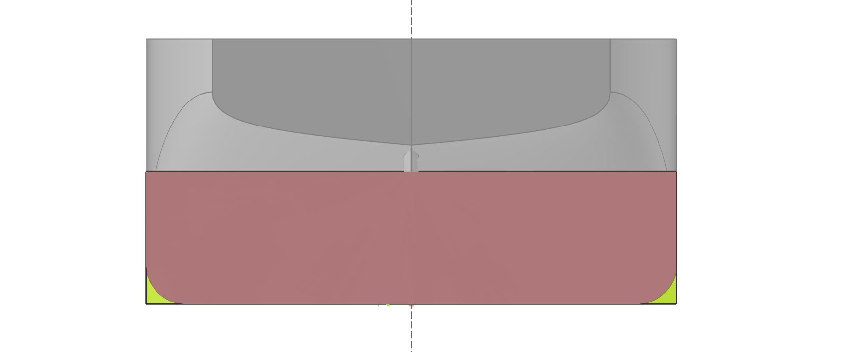
The mainframe coefficient CM, also known as midship coefficient, serves as a two-dimensional analog to the block coefficient, providing insights into the shape of a vessel's hull at the main frame. It is the relation between the sectional area of the main frame (red) to its rectangular bounding box (green) and gives and idea of the shape of the ship at the main frame:
Prismatic Coefficient CP
The prismatic coefficient CP, also referred to as the longitudinal prismatic coefficient, measures the distribution of a vessel's volume along its length, providing insight into the vessel’s hull form and its tendency to generate wave resistance. This coefficient is calculated by dividing the vessel's displaced volume by the product of its sectional area of the main frame and length:

Waterplane Coefficient CWL
The waterplane coefficient CWL illustrates the relation between the waterplane area and this bounding rectangle of its length and beam:

Sectional Area Curve
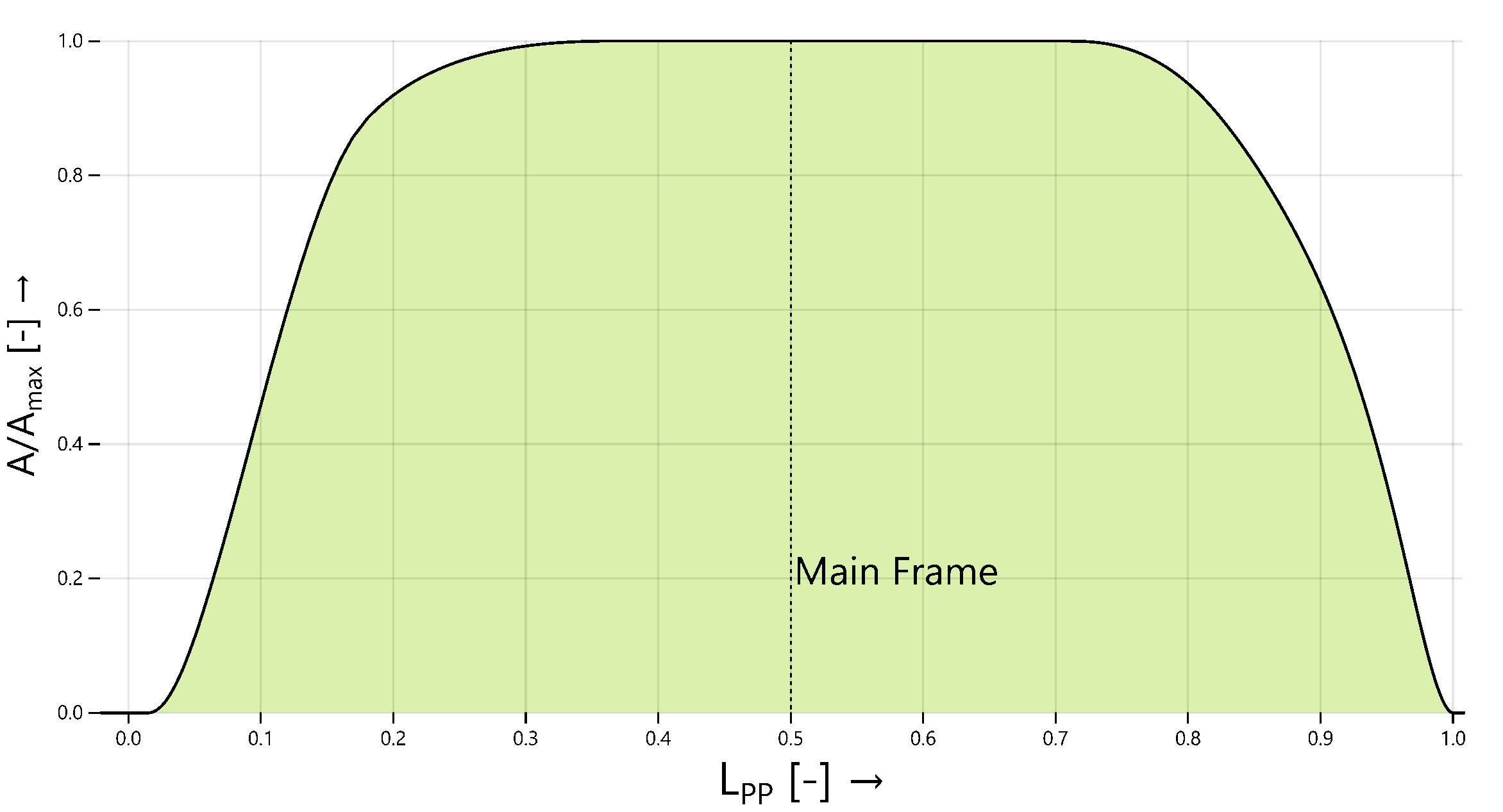
The Sectional Area Curve (short SAC) represents the distribution of volume along the ship's length at a given draft. Integrating the sectional area curve over the full length yields the displacement of the hull
where each point on the curve represents the sectional area at the corresponding x-coordinate. Additionally, the x-coordinate of the SAC's area centroid is equal to the longitudinal center of buoyancy (LCB), calculated as
In the example below, the SAC is displayed in non-dimensional form using the maximum frame area Amax and the length between perpendiculars LPP as a relation.
Hydrostatics Curves
The Hydrostatic Curves, also known as curves of form plot the calculated hydrostatic properties listed above at a series of drafts. Such curves are commonly used in loading and stability studies during the design phase and are available to the operating crew for newly built ships. Since the scale of the different properties are not homogenous, the abscissa of the plot may only display some abstract base unit and the curves offer a conversion factor.
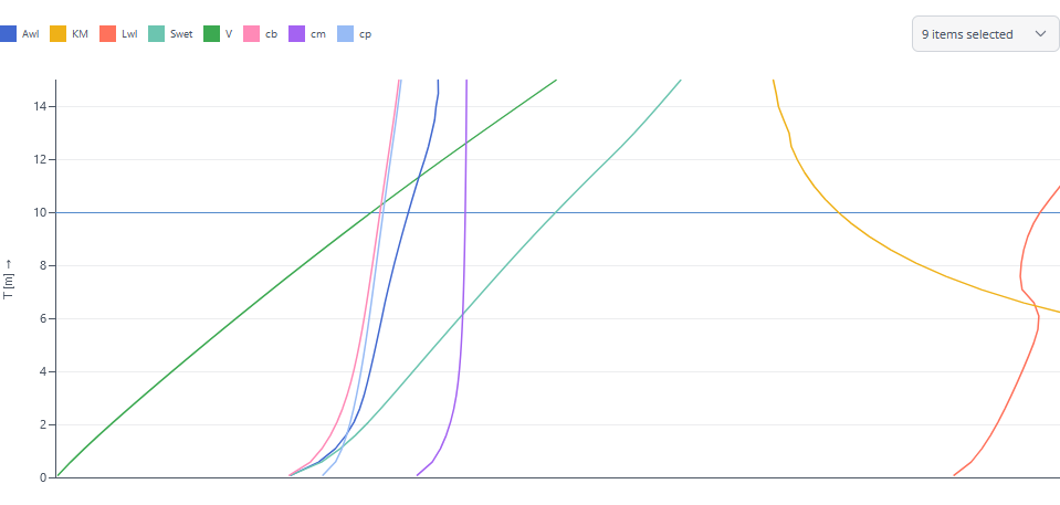
Hydrostatic Calculation in CAESES
With the introduction of the Hydrostatics Viewer, we enable the user to quickly get a good understanding of the hydrostatics of a modelled ship. It contains information about the main dimensions and the sectional area curve of the ship for any number of selected floating conditions. Optionally, the user can add hydrostatic curves for prescribed floating conditions or the calculation of the righting lever curve for any equilibrium floating condition.
Take a look at the hydrostatics tutorial to learn how to set up the hydrostatics computations ins CAESES.
Hydrostatic calculations in CAESES using the Ship Object are performed on the tessellated geometry.
Floating Condition
A floating condition in the sense of hydrostatic calculation describes the static draft as well as heel and trim angle of the ship. A floating condition can either be prescribed by the user to a fixed draft, trim and heel or use the equilibrium condition calculated by specifying a loadcase. Additionally, the corresponding environmental conditions always have to be set in each floating condition.
A loadcase collects any number of point masses (e.g. lightship, cargo, ballast, etc.) and calculates the center of mass of the vessel as well as its total mass to use in the equilibrium calculation.
Environmental Conditions
In order to calculate the ships hydrostatics and do more advanced hydrodynamic calculations like CFD simulations, the fluids physical properties in which the vessel operates have to be known. Therefore, the environmental conditions collect these physical properties in one container to make them reusable and easily extendable.