Planar Transom and Deck Modeling
This tutorial will explore a streamlined approach to modeling a planar transom and deck surface. While there are various methods to accomplish this, the technique presented here emphasizes efficiency and reliability. We'll use the transom and deck faces of a hull as our example, guiding you through each step to achieve the desired results. The only prerequisite for this method is having a planar curve as your starting point.
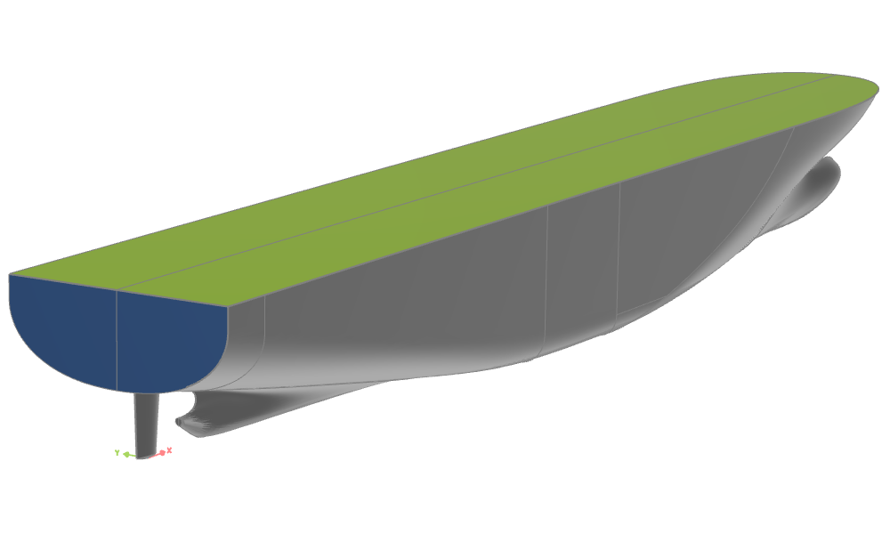
To follow this tutorial, you may use your own geometry or work with any of the hull models provided, e.g. the one from the Lackenby Tutorial:
Get StartedThe idea is to use one of the BRep Closing Operations, namely the Close Planar Open Edges. The input argument is a reference point which is used to detect the closest planar open edge. If this edge does not represent a closed loop it will then be closed with a straight segment from end to start. Alternatively an extrusion towards a principle plane can be chosen. A NURBS Surface will be created and trimmed based on this loop to create the resulting BRep face.
Transom Face
Start with a BRep and add the initial geometry as an add sources operation. As a second operation choose Closing > Close Planar Open Edges.
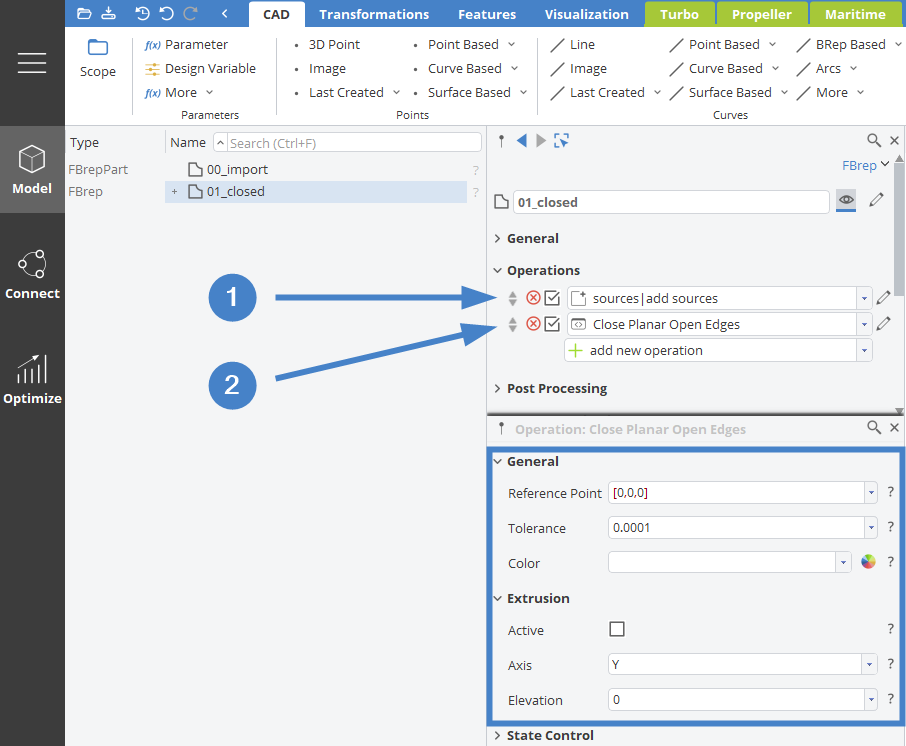
The Closing Operation allows for a set of additional input arguments to be specified. For the Reference Point it is important that you choose this point such that it reliably detects the edge you intend to close. In case of the transom edge in the given example, the minimum x-, maximum y-extension and half the overall height will work even if mayor shape variations where to be expected. If we insert the following expression into the corresponding editor field, we will create such a reference point and assign it simultaneously as shown in the animation below:
point pRef(|00_import.getmin():x,|00_import.getmax():y,|00_import.getmax():z*.5)


If necessary, adjust the tolerance setting and choose a distinct color for the newly generated face. In the present example it is also necessary to activate the extrusion option to make sure the resulting face covers the entire transom up to the deck level.
Deck Face
For the deck we will follow the same. To reliably detect the correct edge, the reference point can be located e.g. halfway along the x-extension of the hull, at maximum y- and z-extension:
point pRef((|00_import.getmin():x+|00_import.getmax():x)*.5,|00_import.getmax():y,|00_import.getmax():z)
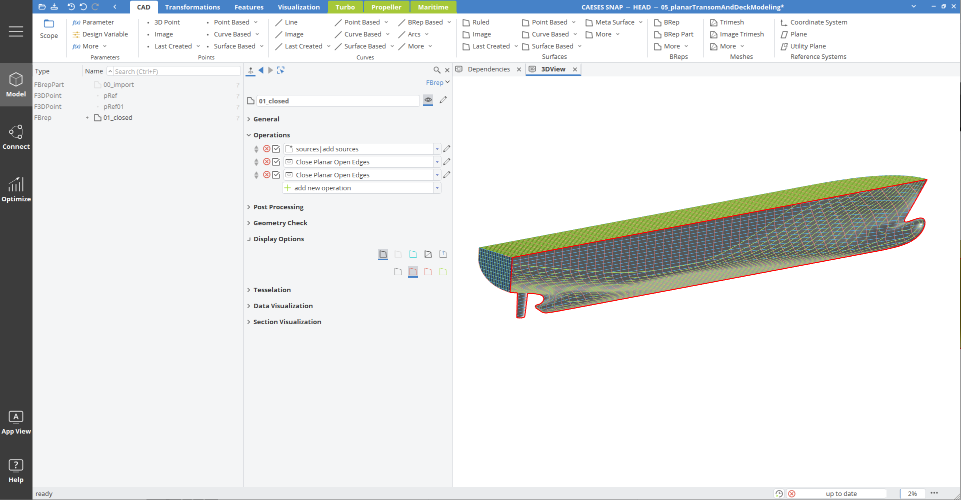
The result should look as follows:
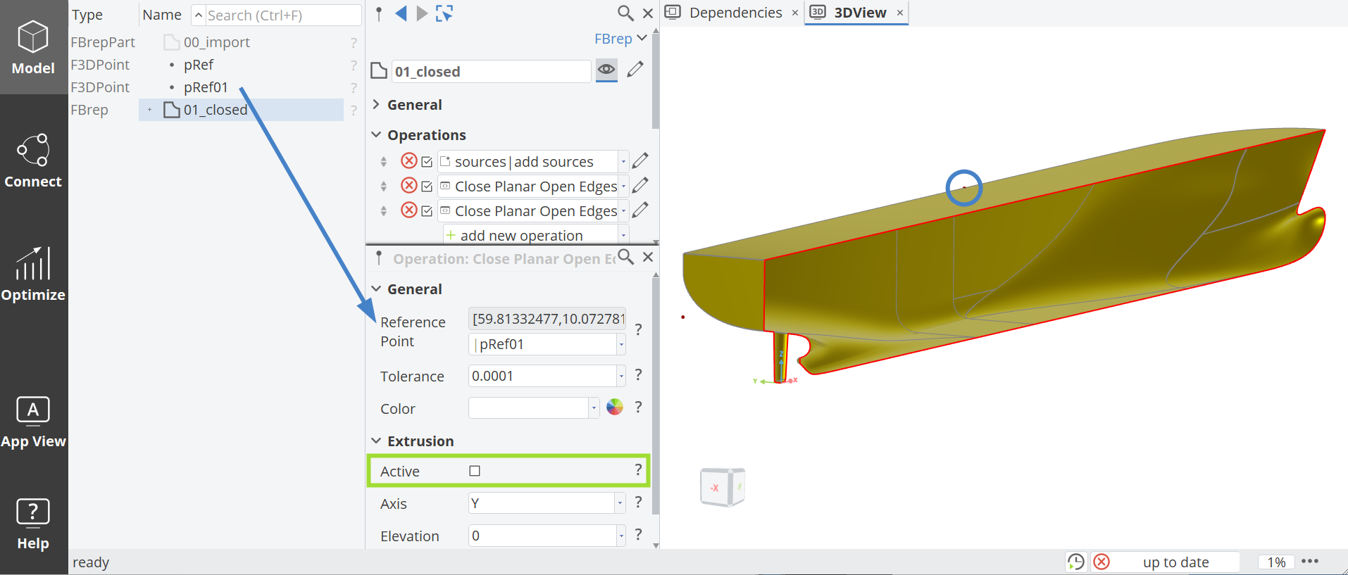
Note that in this case, the optional extrusion is not needed as the referenced edge starts and ends in the center plane at y = 0.
Final Inspection
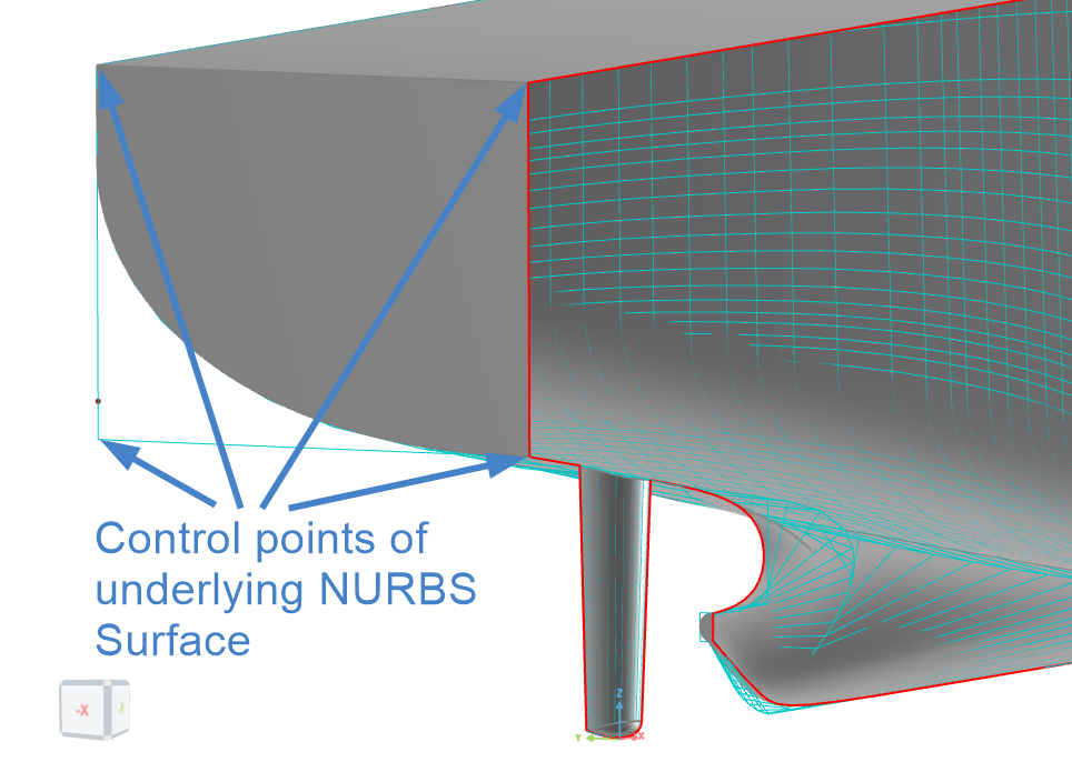
If we hide the initial geometry and look at the resulting BRep in 3D we should find that the newly generated patches share a closed edge with the initial geometry. If we choose to visualize the control polygon of the BRep, we can see that indeed a very simple, rectangular NURBS surface has been created and trimmed based on the selected 3D loop. This method is more efficient and reliable than modeling the patches based on e.g. Ruled Surfaces or similar.
CAESES Project File
If you want to take a look at the finalized parametric model you can find the resulting CAESES project file planar-transom-and-deck-modeling.cdb here: