Input Geometry
This is the area where you define which geometry needs to be exported, and in which format.
Creation
In the Connect workspace (1), click on the plus icon in the upper left corner of the Input Geometry area to add a new entry (2). Use the search bar on the top of the object tree to look for the right geometry object (3). Then simply drag & drop geometry from the object tree into the list (4).
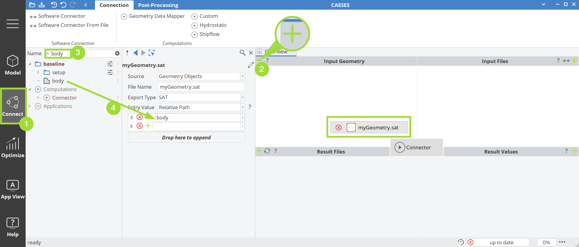
Choose a name and a format for the entry.
Source
For a selected input geometry entry, there are different sources possible that can be used to define which data needs to be exported.
Geometry Objects
In most cases, you would choose "Geometry Objects" to export a geometry from your project.
Feature Definition
Sometimes you want to export very specific data in a specific file format that is not readily available in CAESES. In such a situation, you can write your own export using a feature definition. This feature definition needs to contain at least one object of type "FFile" to show up in this editor. See the section "Features" and chapter "File I/O" of this help for more information about writing custom files in CAESES.
Data Connection
You can also have a data connection such as a 3D volume mesh that you want to deform and export automatically for each new design candidate during a study etc. For this purpose, choose this source and drag & drop your data connection (located in the connections tab) in here.