Propeller Tools and Analysis
This tutorial highlights various functionalities available under the Propeller Tab in CAESES, demonstrating different tools and analyses that users can perform within the software.

These features, illustrated in the figure above, enhance the propeller design workflow in CAESES, helping users gain a better understanding of the design through various estimations and calculations without the need for external software.
B-Series Propeller Generator
For the purposes of this tutorial, a B-Series propeller will be used. This type is a standard conventional propeller in marine propulsion, widely tested and known for reliable performance. You can generate such a propeller using our online B-Series Propeller Generator.
There are two available options:
-
Design Tool:
A preliminary design tool where you input information about the ship and propulsion system. This tool quickly calculates a suitable propeller shape that meets your requirements in just a few seconds. -
Geometry Tool:
If you already have your geometric blade parameter values, such as pitch, rake, thickness and diameter. The fast blade geometry generator provides direct and accurate control over the blade shape.
Design Tool
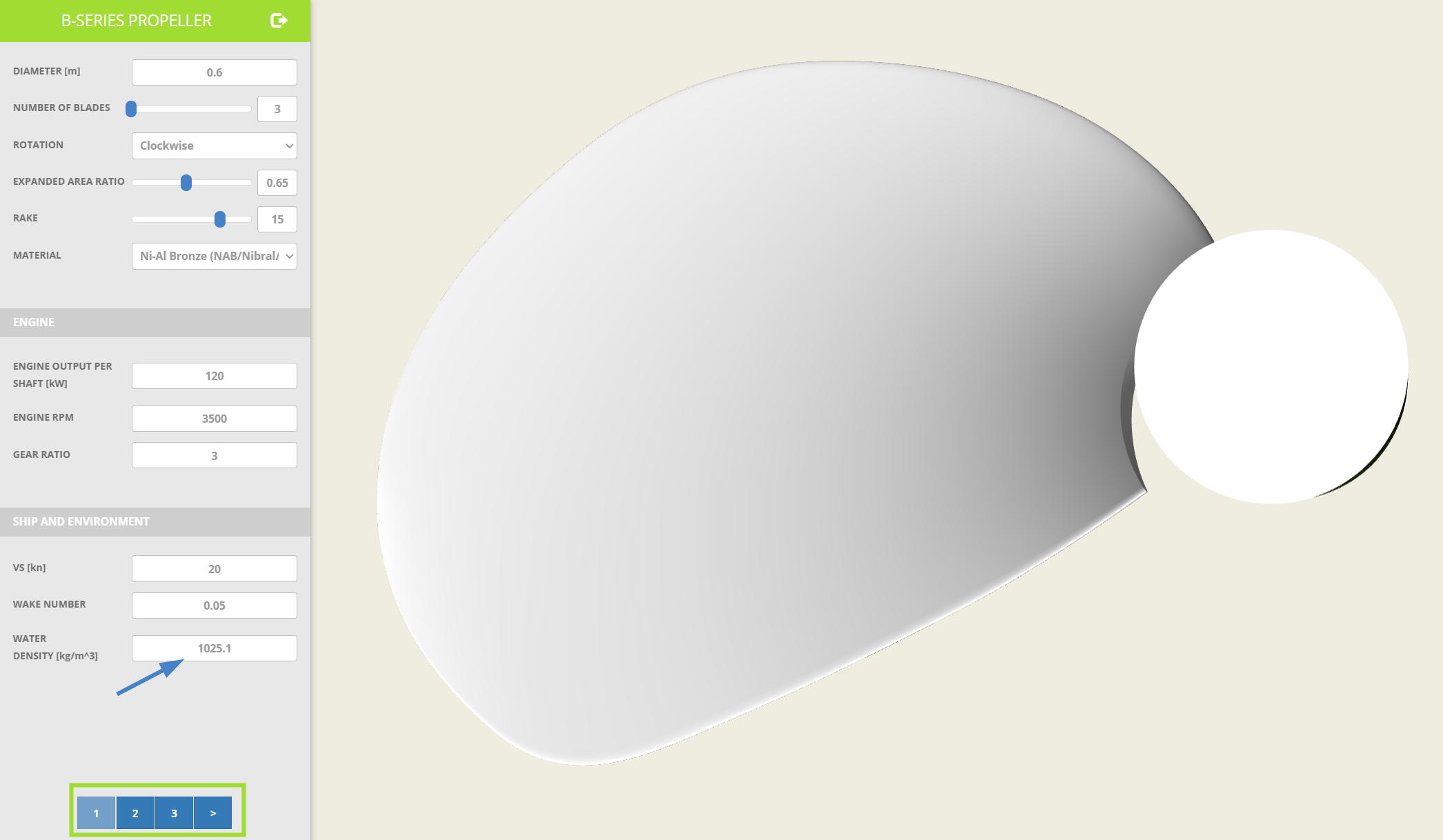
The propeller used in this tutorial will be generated using the Design Tool. Internally, the provided inputs from the first page (shown in the figure below) are categorized into three groups:
- B-Series Propeller Parameters
- Engine Information
- Ship and Environment
The Design Tool includes three pages, which you can navigate through by scrolling at the bottom.
On the first page, only the water density is adjusted from 1025.9 kg/m³ to 1025.1 kg/m³.
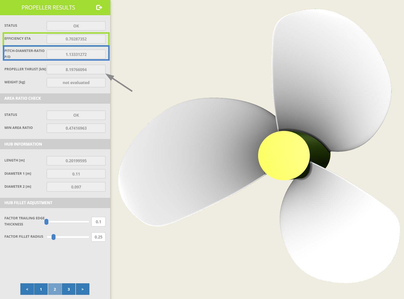
On the second page, propeller results are displayed. Internally, based on the provided inputs, an optimization process searches for the Pitch-Diameter Ratio (P/D, marked in the green rectangle) that achieves the highest efficiency (ETA, marked in the blue rectangle) for the given engine torque. Using the B-Series polynomials, the Open Water Characteristics of the B-Series propeller can be determined for the specified inflow conditions and blade parameters, allowing for the calculation of the resulting thrust.
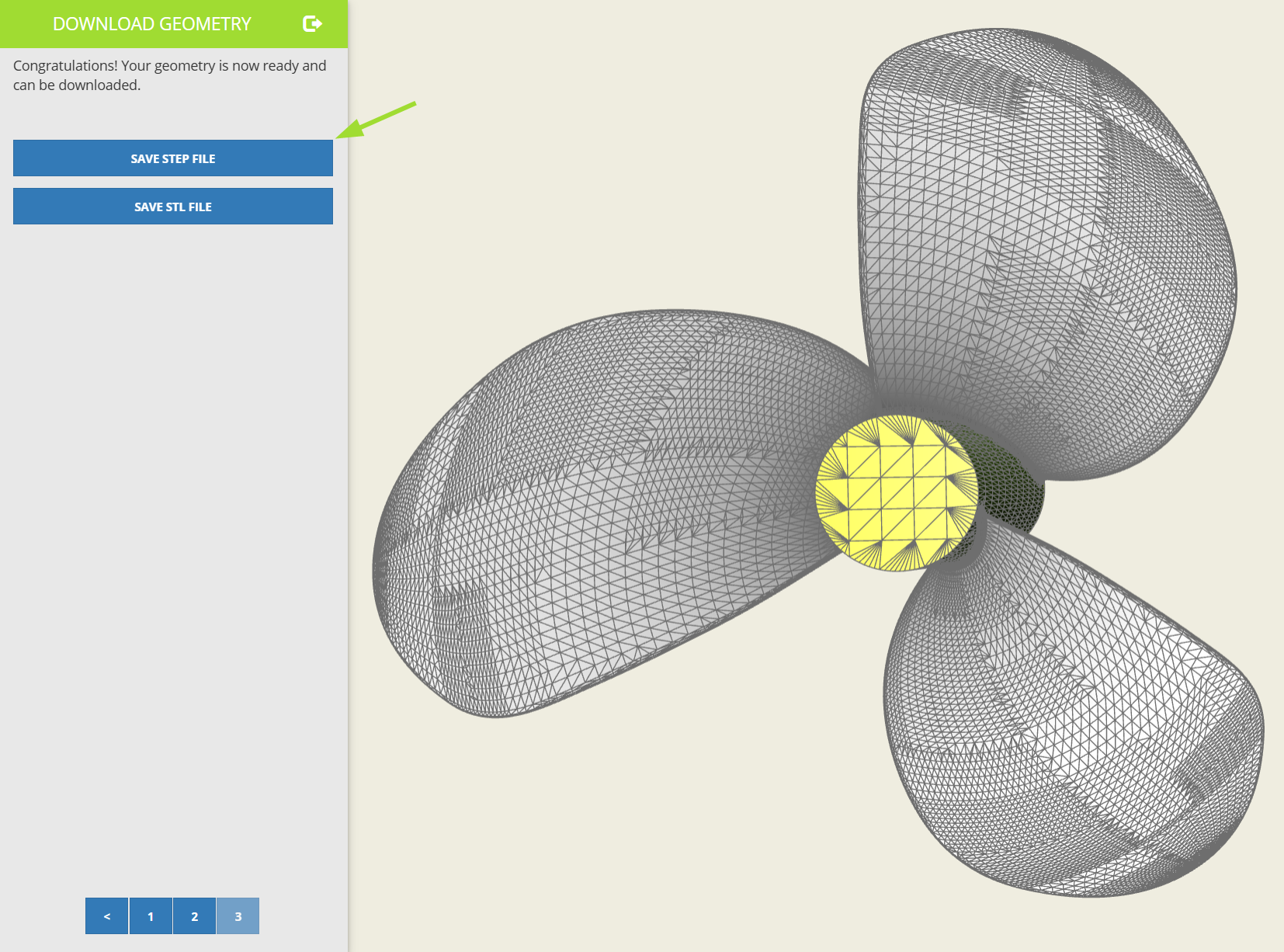
On the third page, you can download the propeller geometry in STEP or STL format. The triangulation of the model is displayed in the figure below. For this tutorial, the geometry is saved in STEP format because it includes more detailed geometric information and provides a smooth, unlike the STL format, which represents geometry via triangles.
Imported Propeller
To import the STEP file into CAESES, first click the Menu button (burger menu icon) on the Workspace Bar, select the Import tab and then click the icon for importing a STEP file. The process is shown below:
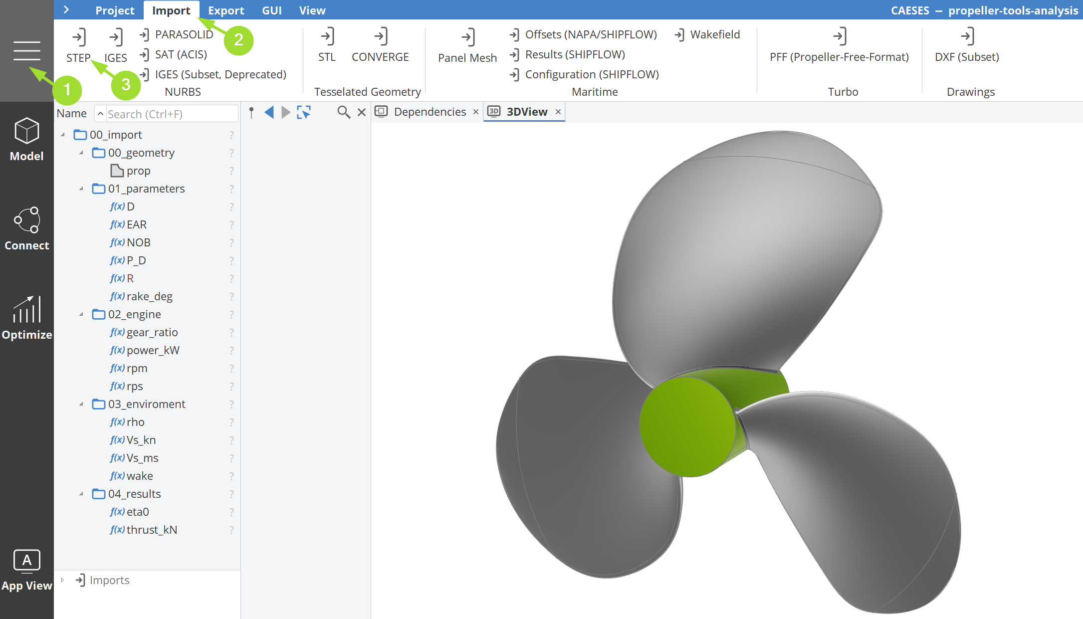
Once the geometry has been imported, you need to create the necessary scopes and structure the project as shown in the image above. Afterwards, you can retrieve the parameter values from the Design Tool web application.
Propeller Analysis
With the geometry import now complete, we can proceed with analyzing the propeller using the built-in features provided by CAESES.
Blade Analysis
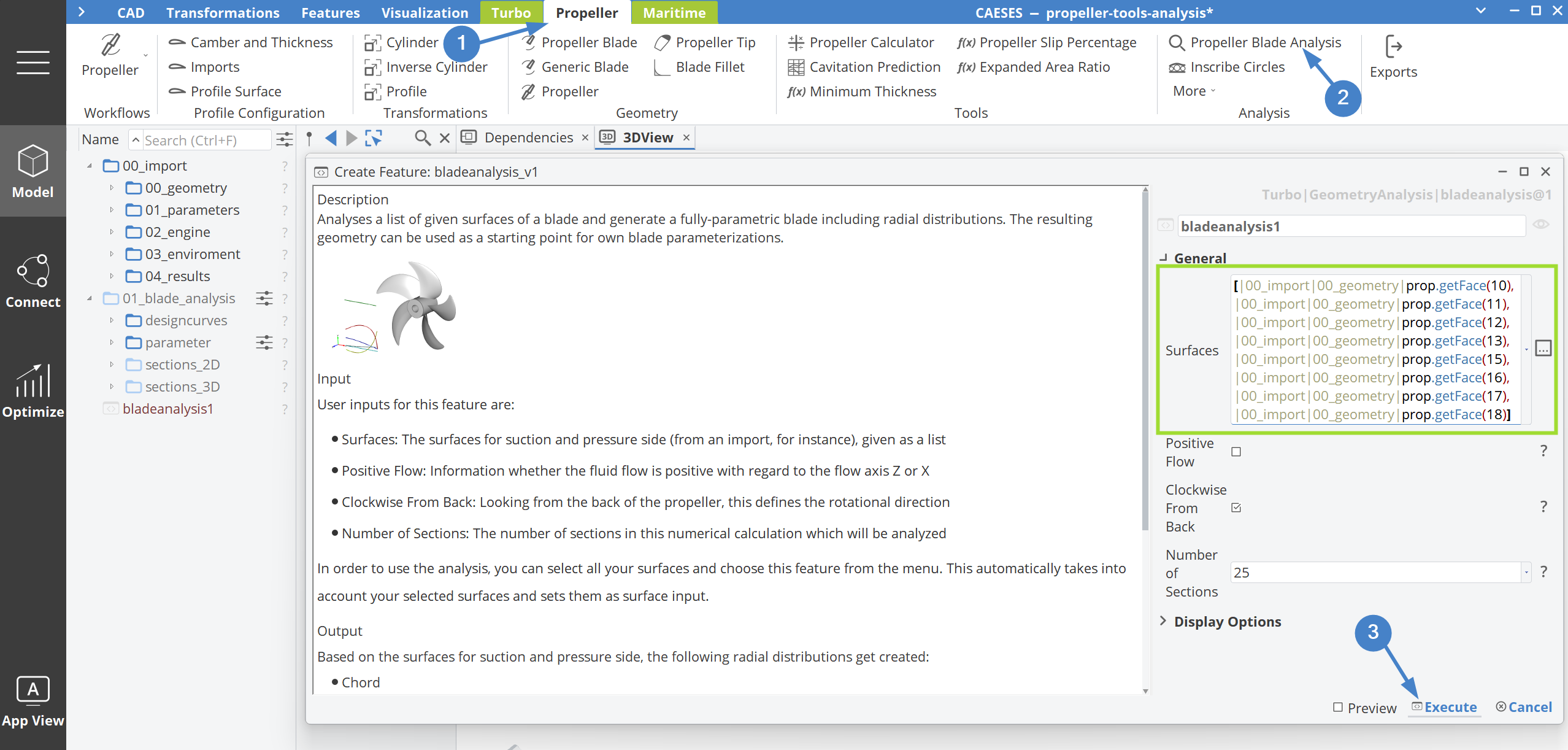
We start by analyzing the propeller blade using the Propeller Blade Analysis feature. This feature requires a list of surface inputs. These surfaces can be extracted from the imported propeller geometry, as shown in the figure below, and should include only the blade geometry along with the tip region, explicitly excluding the hub and fillet. After fine-tuning the remaining inputs, the feature can then be executed.
ResultsUpdatedThis content was recently updated.
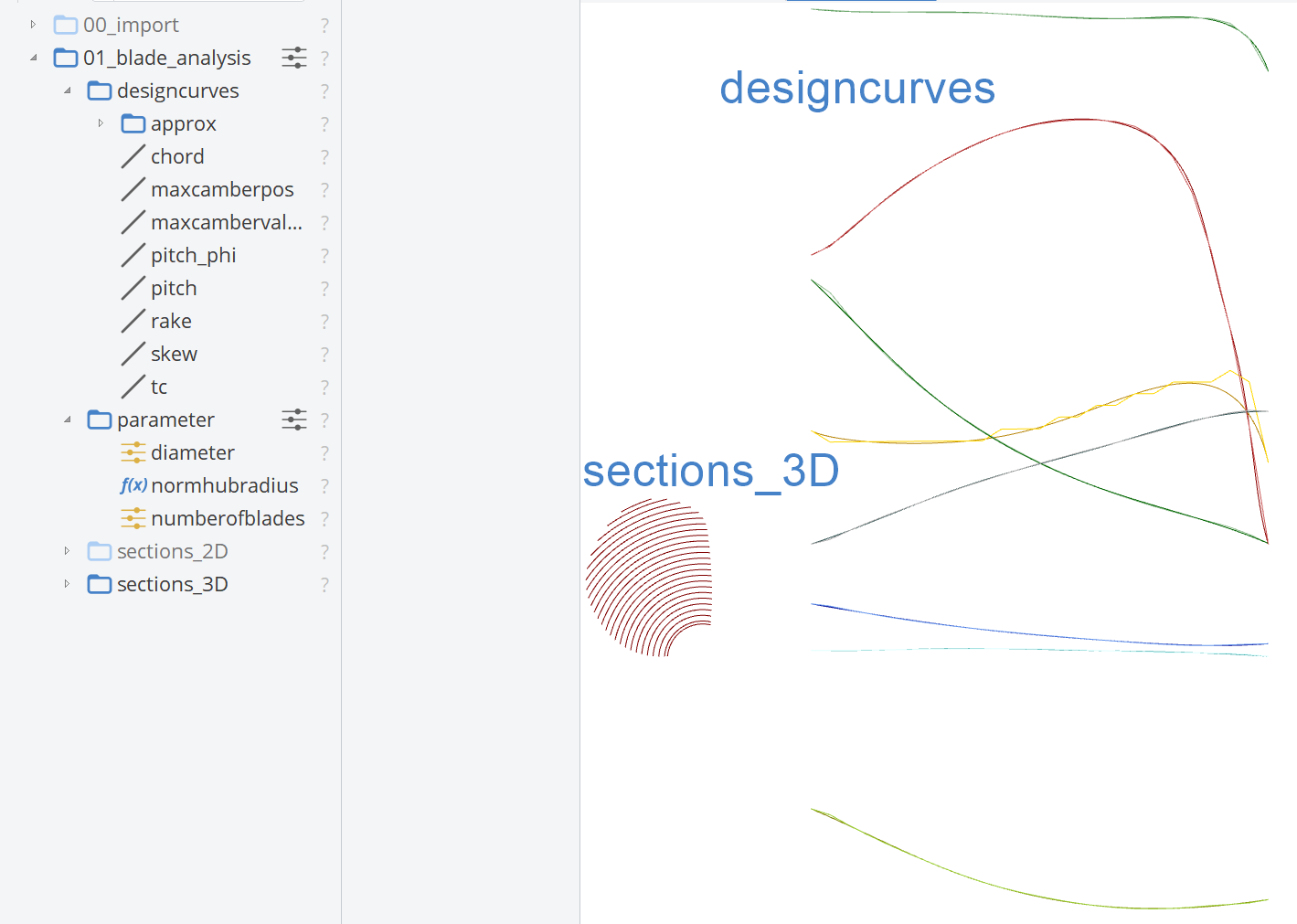
This feature analyzes the propeller blade by slicing it into cylindrical sections, providing the following results:
- Design Curves: Approximations representing Radial Distributions.
- Parameters:
- Main propeller parameters including:
- Propeller Diameter
- Normalized Radius of the Hub
- Number of Blades
- Main propeller parameters including:
- Normalized 2D Sections
- 3D Sections
The Design Curves have two outcomes: the polyline, which connects the resulting points at each section, and the approximated curves, which are C-spline curves. These C-spline curves are stored under the scope named approx.
Other results generated by the feature can be deleted since they aren't required for the purposes of this tutorial. All retained results should be organized under a scope named 01_blade_analysis.
Since only one blade of the propeller is used as input, the resulting parameter for the number of blades is set to 1. Be sure to update this parameter to reflect the actual number of blades. In this case, it is 3. The diameter of the propeller and the normalized radius of the hub are calculated properly.
For the generation of a smooth propeller geometry based on the analysis, it is recommended to use the approximated curves rather than the linear analyzed curves.
Profile Analysis
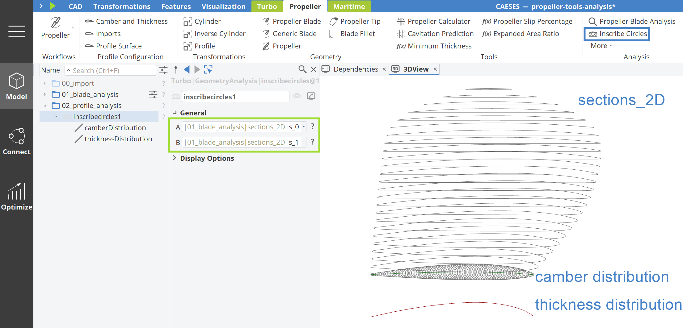
In addition to the Propeller Blade Analysis, we can perform a detailed analysis of the blade profile sections in 2D. Since we already have the 2D sections from the previous analysis, we can utilize the Inscribe Circles feature available under the Analysis category in the Propeller tab.
For this analysis, the Suction Side and Pressure Side profiles serve as inputs. The Inscribe Circles feature generates circles between the Trailing Edge and Leading Edge for the given profile section, providing the Thickness & Camber Distribution.
When inputting the sides (A and B), the sequence doesn't matter; you can assign either the suction side or the pressure side as A or B.
Propeller Additional Parameters
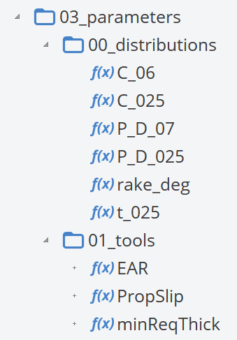
In this section, additional parameters will be calculated either as values retrieved from the Radial Distributions or by using the Propeller Tools features in CAESES.
From Distributions
The following values are extracted from the Radial Distributions using the listed functions:
-
Chord: Chord length at 0.25 and 0.6 r/R values
C_025=|01_blade_analysis|designcurves|chord.fv(0, 0.25):Y * |01_blade_analysis|parameter|diameter / 2 * 1000C_06=|01_blade_analysis|designcurves|chord.fv(0, 0.6):Y * |01_blade_analysis|parameter|diameter / 2 * 1000
-
P/D: Pitch-Diameter Ratio at 0.25 and 0.7 r/R values
P_D_025=|01_blade_analysis|designcurves|chord.fv(0, 0.25):Y * |01_blade_analysis|parameter|diameter / 2 * 1000P_D_07=|01_blade_analysis|designcurves|chord.fv(0, 0.6):Y * |01_blade_analysis|parameter|diameter / 2 * 1000
-
Rake: Rake angle at the tip, in degrees
rake_deg=atan((|01_blade_analysis|designcurves|rake:End:Y - |01_blade_analysis|designcurves|rake:Start:Y) / (|01_blade_analysis|designcurves|rake:End:X - |01_blade_analysis|designcurves|rake:Start:X))
-
Thickness: Thickness at 0.25 r/R
t_025=|01_blade_analysis|designcurves|tc.fv(0, 0.25):Y * |01_blade_analysis|parameter|diameter / 2 * 1000
Expanded Area Ratio UpdatedThis content was recently updated.
In CAESES, under Propeller Tools, there is a feature that calculates the Expanded Area Ratio of a propeller. The required inputs for this calculation are the Chord Distribution, the Radius, and the Number of Blades of the propeller.
Additionally, the feature calculates the Expanded Area (AE) and the Propeller Disc Area (A0).
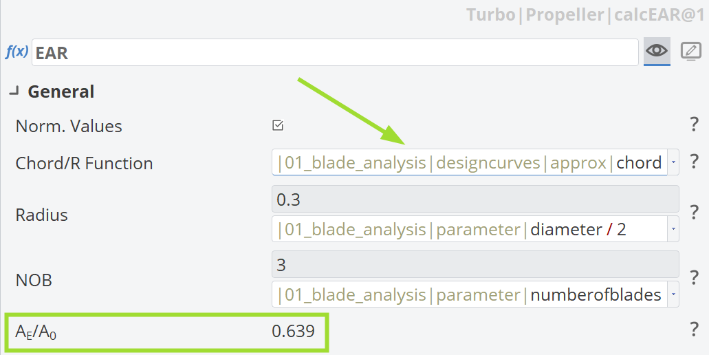
There is a slight difference between the Expanded Area Ratio provided by the Design Tool and the value calculated by this feature (e.g., 0.65 vs. 0.639). This discrepancy arises from small differences in the chord distribution extracted by the Propeller Blade Analysis feature. Additionally, the approximated chord distribution, represented as a C-Spline curve, is used here.
Propeller Slip
Another feature in Propeller Tools calculates the Propeller Slip percentage based on the propeller geometry, engine information, and the ship's speed properties. These inputs can be retrieved from the Design Tool.
Propeller slip refers to the difference between the actual distance traveled by a ship and the theoretical distance, which is the product of the propeller pitch and the number of revolutions. It is usually expressed as a percentage and may even be negative when favorable conditions such as a current or a following wind are present.
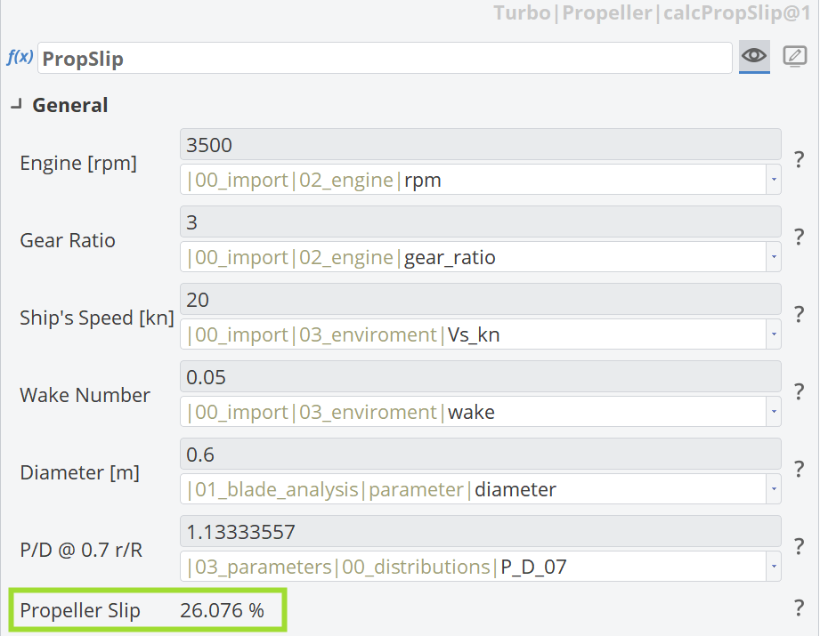
Most of the inputs are retrieved from the Design Tool.
Minimum Required Thickness
This feature in Propeller Tools calculates the minimum required thickness for marine propellers, ensuring compliance with regulations set by various classification societies such as ABS, BV and RINA.
The input parameters include:
- Propeller type (Fixed-pitch or Controllable-pitch)
- Diameter
- Rotational speed
- Power at rated speed
- Expanded area ratio (calculated previously using the corresponding feature)
- Number of blades
- Radial information (chord, pitch, skew, and rake)
- Propeller material
It also supports unconventional geometries such as highly skewed or wide-tip (ducted) propellers. The output includes minimum required thickness values at different radial locations and the corresponding properties of the selected material.
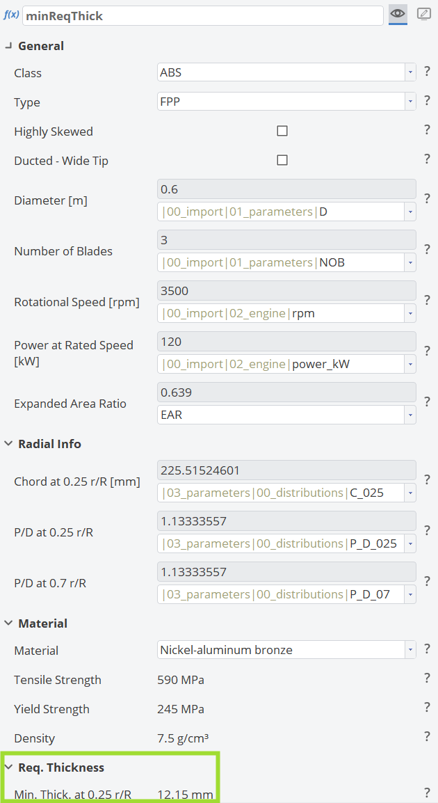
Most of the inputs are retrieved from the Design Tool.
Propeller Property Calculator
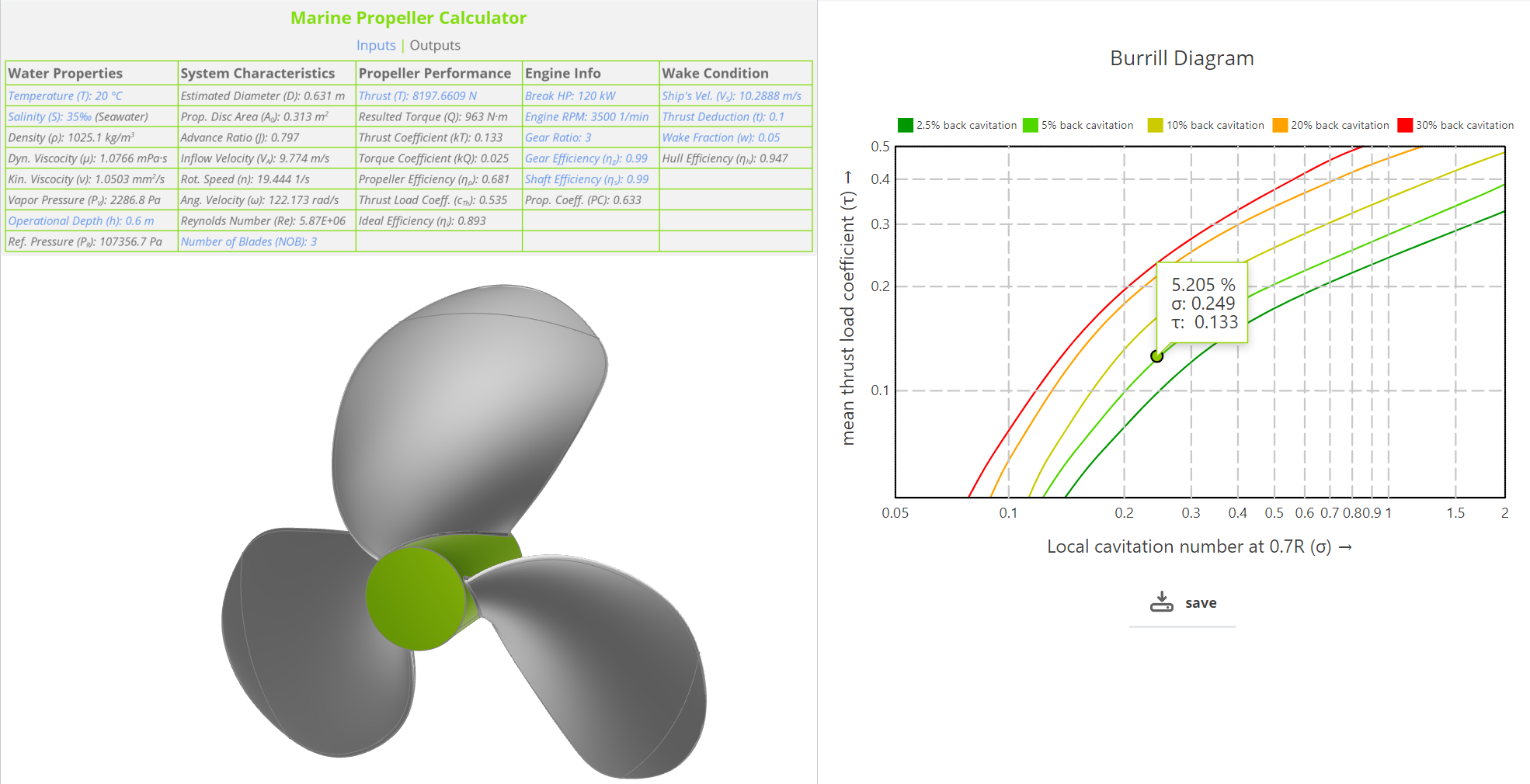
The Propeller Property Calculator, another feature from Propeller Tools, is designed to compute Water Properties using semi-empirical equations and various System Characteristics. It also evaluates Propeller Performance based on Engine Information and provides Estimation for Diameter and Cavitation Risk. These functionalities are summarized in the figure below.
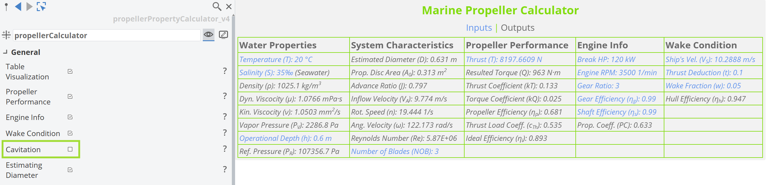
In the figure above, a table is displayed within the 3D View of CAESES. It shows different categories evaluated by the calculator, each organized into columns. These categories can be included by selecting the corresponding checkboxes.
Different colors are used to distinguish between Inputs and Outputs, making it easier to visually differentiate the values since many of them are present in the same view.
Here, the estimated diameter for a suitable propeller with these properties is 0.631 meters, which is quite close to the original diameter of 0.6 meters.
It is not necessary to use the full functionality of the calculator, as it includes a wide range of information. The table is dynamic, allowing you to customize it according to your needs.
For example, the Cavitation Risk functionality is not enabled in this case, as a separate tool from Propeller Tools will be used for cavitation prediction.
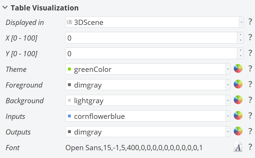
Table Visualization
Below is an example of how the table with Inputs & Outputs from the feature can be visually customized:
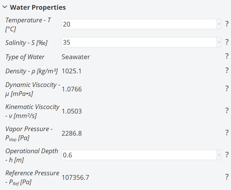
Water Properties
The figure below shows the Inputs & Outputs for the Water Properties section.
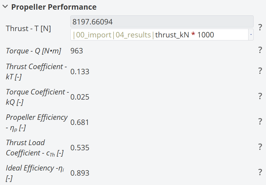
Propeller Performance
The figure below shows the Inputs & Outputs for the Propeller Performance section.
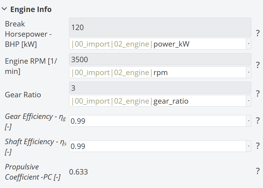
Engine Info
The figure below shows the Inputs & Outputs for the Engine Info section.
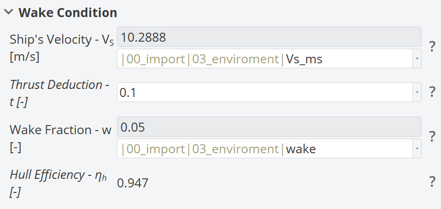
Wake Condition
The figure below shows the Inputs & Outputs for the Wake Condition section.
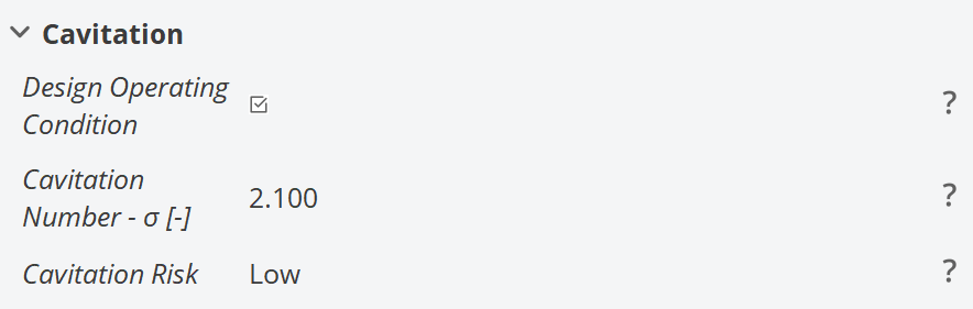
Cavitation Risk
The figure below shows the Inputs & Outputs for the Cavitation Risk section.
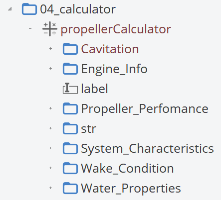
Results
The results generated by this feature are structured as shown below. By unfolding the corresponding scope, you can retrieve the outputs.
Cavitation Prediction
Another feature from the Propeller Tools is the Cavitation Prediction using the Burrill Diagram. This diagram is a widely recognized criterion for fixed-pitch conventional propellers in the preliminary design stage. It helps designers select suitable propellers by estimating the percentage of cavitation on the back side of the propeller blade.
The Burrill Diagram correlates the mean thrust load coefficient on the blades (τ on the y-axis) with the cavitation number at 0.7 radius (σ on the x-axis).
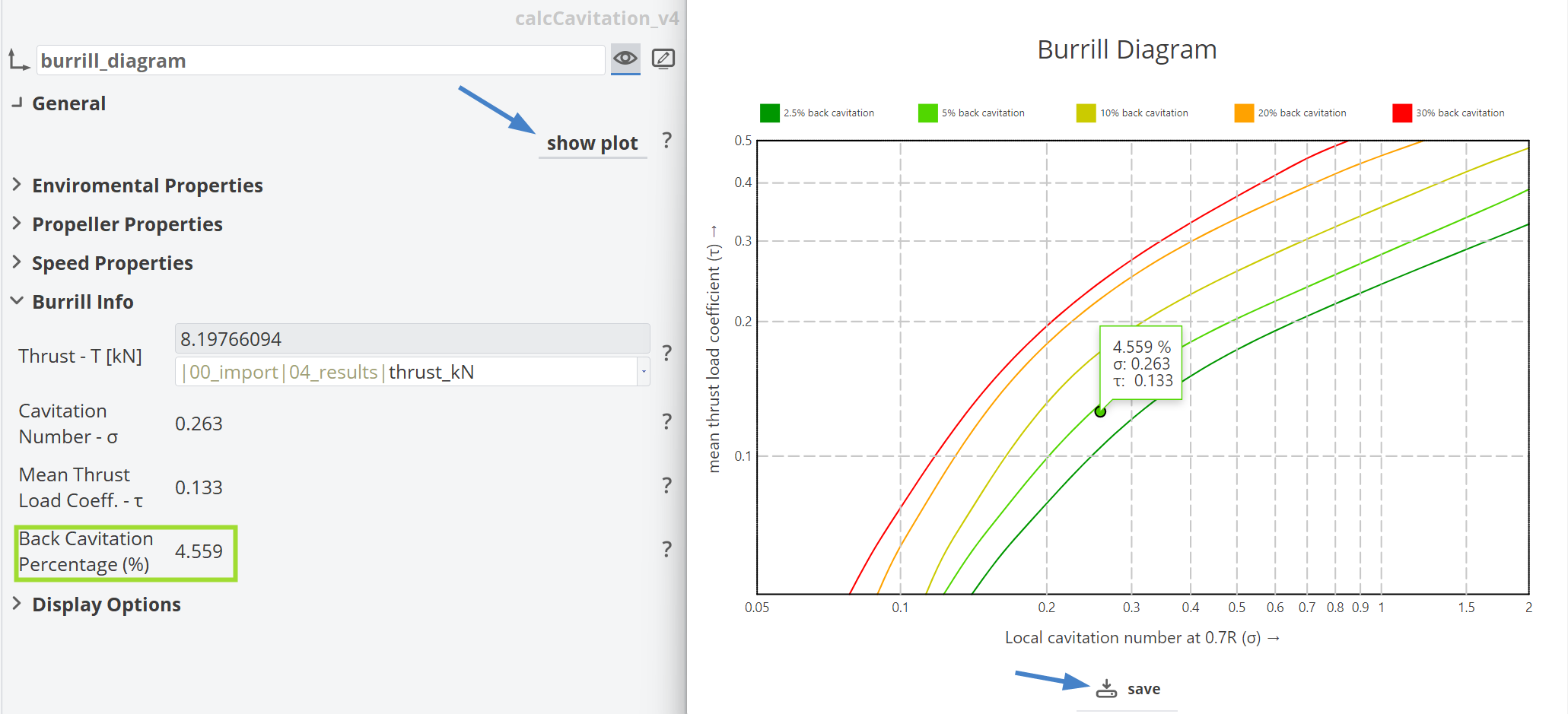
The Burrill Diagram can be displayed in the Plotter View by pressing the Show Plot button. It shows the evaluation point and the estimated back cavitation percentage based on its proximity to the corresponding isocurves of 2.4%, 5%, 10%, 20%, and 30% back cavitation. The diagram can also be exported in SVG format.
Any design with less than 10% back cavitation is generally considered a good design for conventional propellers. In our case, the estimated cavitation is 4.559%, which is below the threshold and indicates a well-performing propeller. But we didn’t expect anything less from a B-Series Propeller.
Inputs & Outputs
The GUI of this feature utilizes inputs from previous tools such as the Propeller Property Calculator, the Calculation of Expanded Area Ratio and also from the Design Tool.
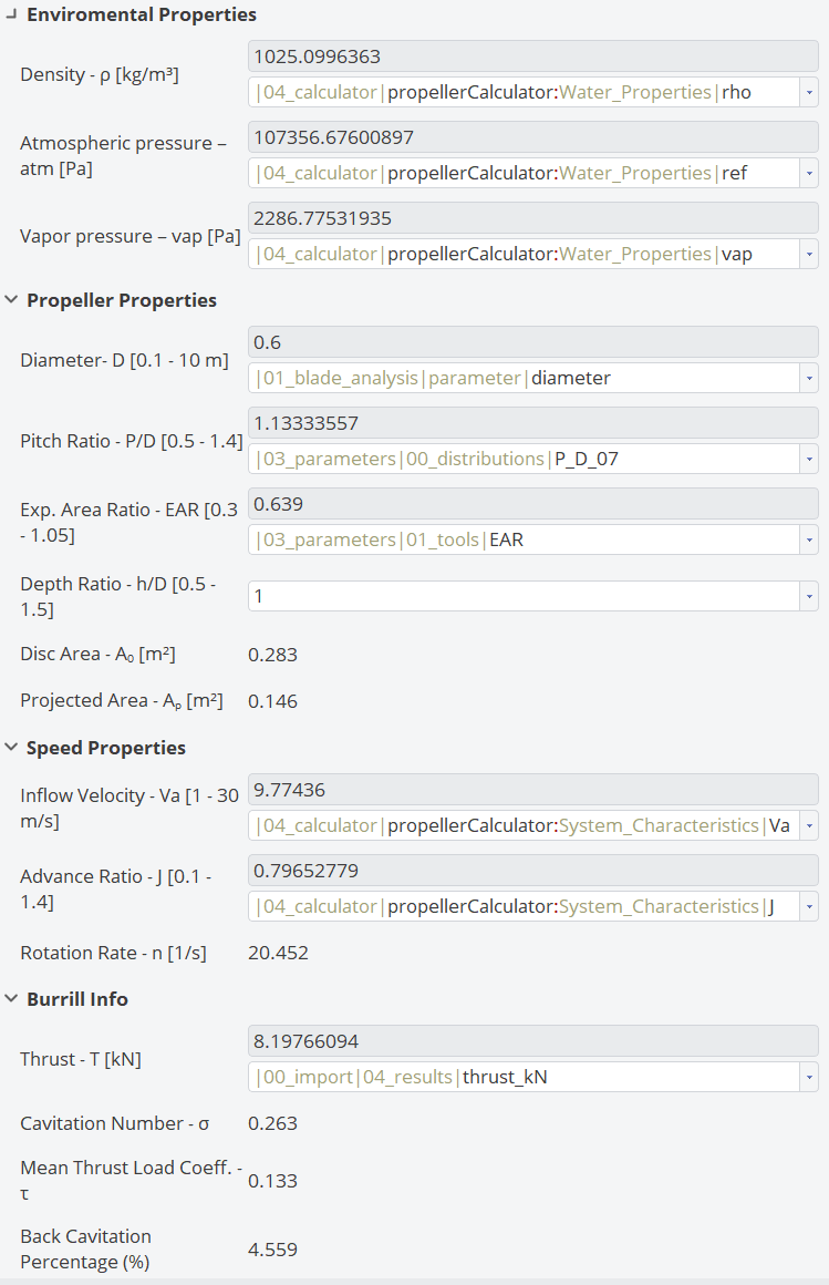
The Projected Area (AP) of the propeller is calculated by this feature.
Conclusion
This tutorial presents a complete workflow using the Web-App Design Tool of CAESES. The idea is to begin with an imported geometry, which can be any kind of propeller and explore the available features within Propeller Tools & Analysis.
You may not need to use every feature, but it is helpful to know what is available in the Propeller tab. Following this workflow can offer more insight into your propeller geometry. These tools are also very useful during the preliminary and concept design phases.
CAESES Project File
If you want to take a look at the finalized model you can find the resulting CAESES project file propeller-tools-analysis.cdb here: