Blade Geometry
Radial Distributions
Radial distributions in marine propellers refer to the variation of different parameters along the radius of the propeller blade, from the hub to the tip. These parameters influence the geometry of the propeller in the spanwise direction. The distributions are usually shown in a normalized diagram where the outer radius of the propeller is equal to one.
Profile Section Geometry: Chord, thickness and camber refer to the geometric characteristics of the profile/cross-section.
Blade Geometry: Pitch, skew and rake refer to the geometric characteristics of the blade.
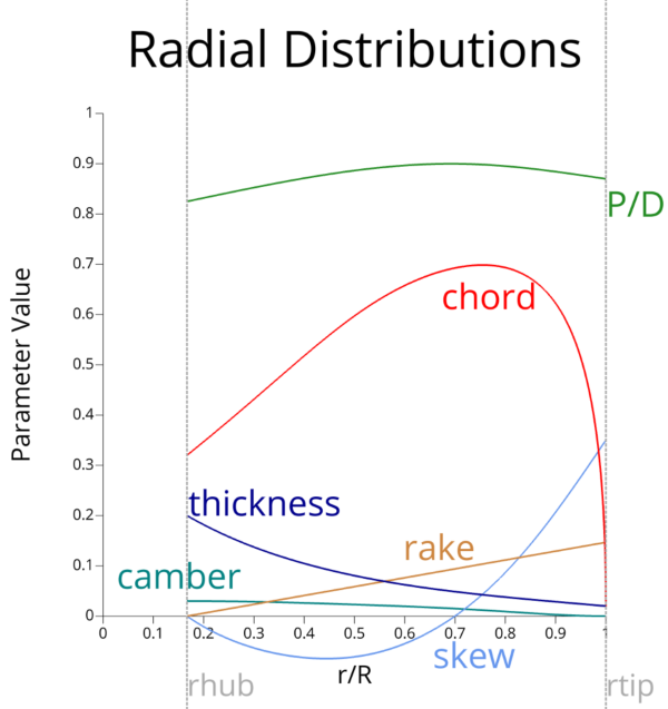
In CAESES radial distribution functions are defined in the global XY-plane in the range [0,1] x [0,1], where the x-coordinate corresponds to the normalized radius: .
Pitch
Pitch refers to the theoretical distance a propeller would move forward in one complete revolution if it were moving through a solid, like a screw through wood. In practice, due to water resistance, the actual distance moved is less than the theoretical pitch. This difference is called propeller slip. The pitch of a propeller significantly affects a vessel's speed and propulsion efficiency.
- Propeller Slip: The difference between the actual distance traveled by a ship and the theoretical distance calculated based on the product of propeller pitch and the number of revolutions.
- Mean Pitch: Refers to the average pitch over the entire span or radius of the propeller blades.
- Nominal Pitch: Refers to the pitch value typically used at along the radius of the blade. It serves as a representative value for the entire propeller blade.
- Pitch Damping: Commonly seen in pitch distribution, where the nominal pitch is maximum and there is damping near the root and tip of the blade due to the influence of the ship's wake and to reduce tip vortex losses.
- Pitch Ratio ( ): The ratio of the mean pitch of a propeller to its diameter. This metric provides a standardized way to understand propeller characteristics globally. Pitch ratios for propellers generally range from
0.5to2.0.
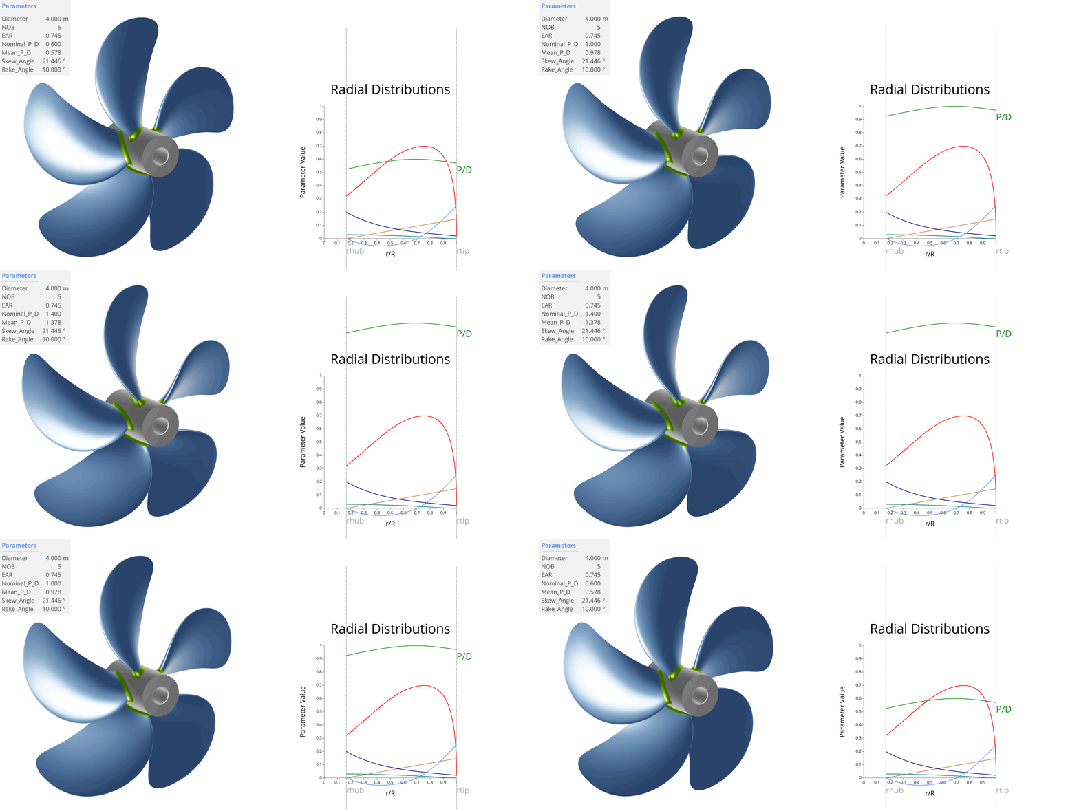
Pitch transforms the torque from the propeller shaft into thrust by redirecting or accelerating water astern. While the advance ratio relates to the angle of attack of the fluid, pitch controls the geometric angle of attack, as depicted in the figure below. A lower-pitch propeller is akin to low gear in a vehicle - acceleration is quick, but top speed is limited. Conversely, a propeller with excessive pitch can achieve higher top speeds per rotation but may suffer from poor acceleration, making it challenging for the boat to plane efficiently.
In CAESES the radial function for the pitch value can be defined either as a function of the pitch angle 'Φ' using degree or as the common value P, i.e. the distance moved forward by the helical line during one revolution. Please note that the pitch value P is normalized with respect to the radius (e.g. for a value P=P/D the pitch factor of the given function needs to be set to 2 in the curve engine editor: [pitchfunction,2]).
Skew
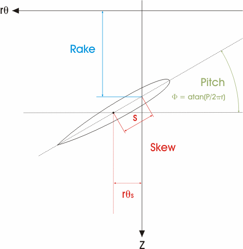
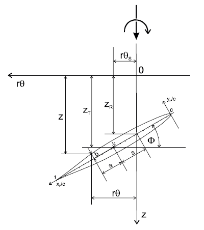
Skew refers to the horizontal displacement of the blade sections of a propeller, as seen from the back view. It essentially describes how much the blades are twisted or swept back in the direction of rotation. Often referred to as the skew angle of a particular section ( ), it is the angle between the reference line and a line drawn through the shaft center line and the mid-chord point of a section at its non-dimensional radius ( ). The skew angle ( ) of a propeller in general is typically defined as the greatest angle along the blade. A typical skew distribution is at , as shown in the animation below.
By skewing the blade, it is possible to reduce vibration levels to less than 30% of an unskewed design. Skewed blades can significantly reduce the vibrations transmitted to the hull because they encounter variations in water flow (such as from the ship's wake) gradually rather than all at once, leading to smoother operation. Skew can also help distribute the pressure load more evenly across the blades, reducing the likelihood of cavitation phenomenon.
Highly Skewed: A high skew propeller has a skew angle of more than 25°. High skew blades are applied to suppress cavitation-induced pressure impulses.
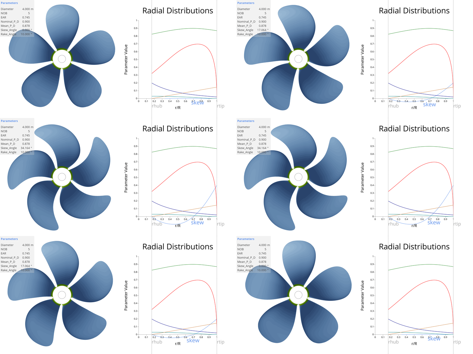
In CAESES a skew radial distribution can either be defined by the angle (i.e. in axial direction view, the angle between the mid-chord position of a section and the reference line) or the distance of the mid-chord position to the projected flow axis. See the following illustrations for more details [18]:
 |  |
Rake
Rake refers to the displacement of the blade relative to its hub, either forward or backward, as viewed from the side. Similar to skew angle, rake angles exist and can also be generated from skew, known as skew-induced rake. Traditionally, rake is a linear distribution varying from forward to backward rake.
- Backward Rake (Positive Rake): Used to increase the effective diameter of the propeller, making it a common choice in propeller design. The slight hull sweep allows the propeller tip to benefit from a greater effective diameter.
- Forward Rake (Negative Rake): Mainly used in applications involving extremely high-speed vessels and highly loaded propellers. Forward rake helps to strengthen the blades and improve performance under heavy loads.
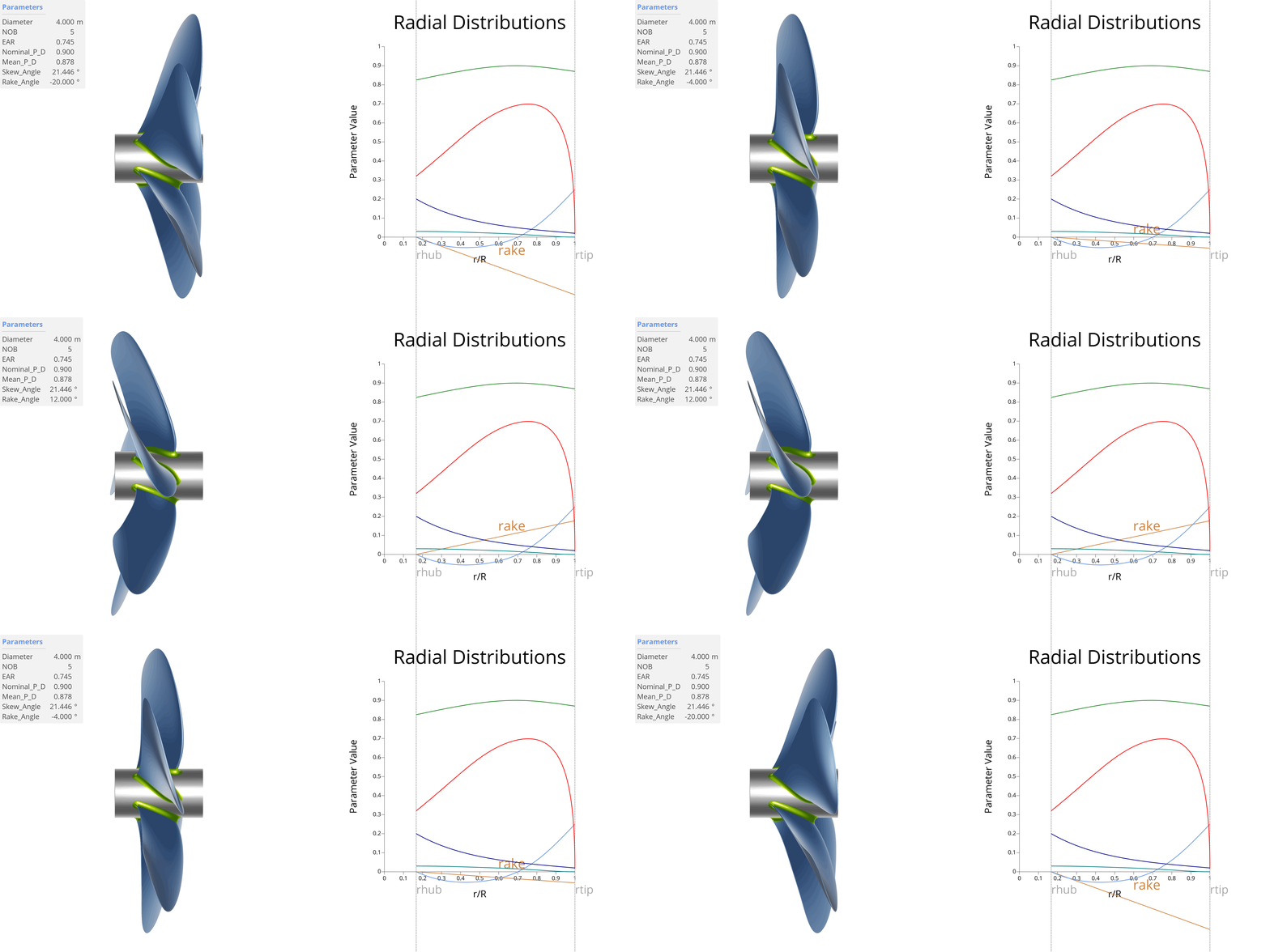
In CAESES the rake function is also expected to be normalized with respect to the real radius.
Tip Rake
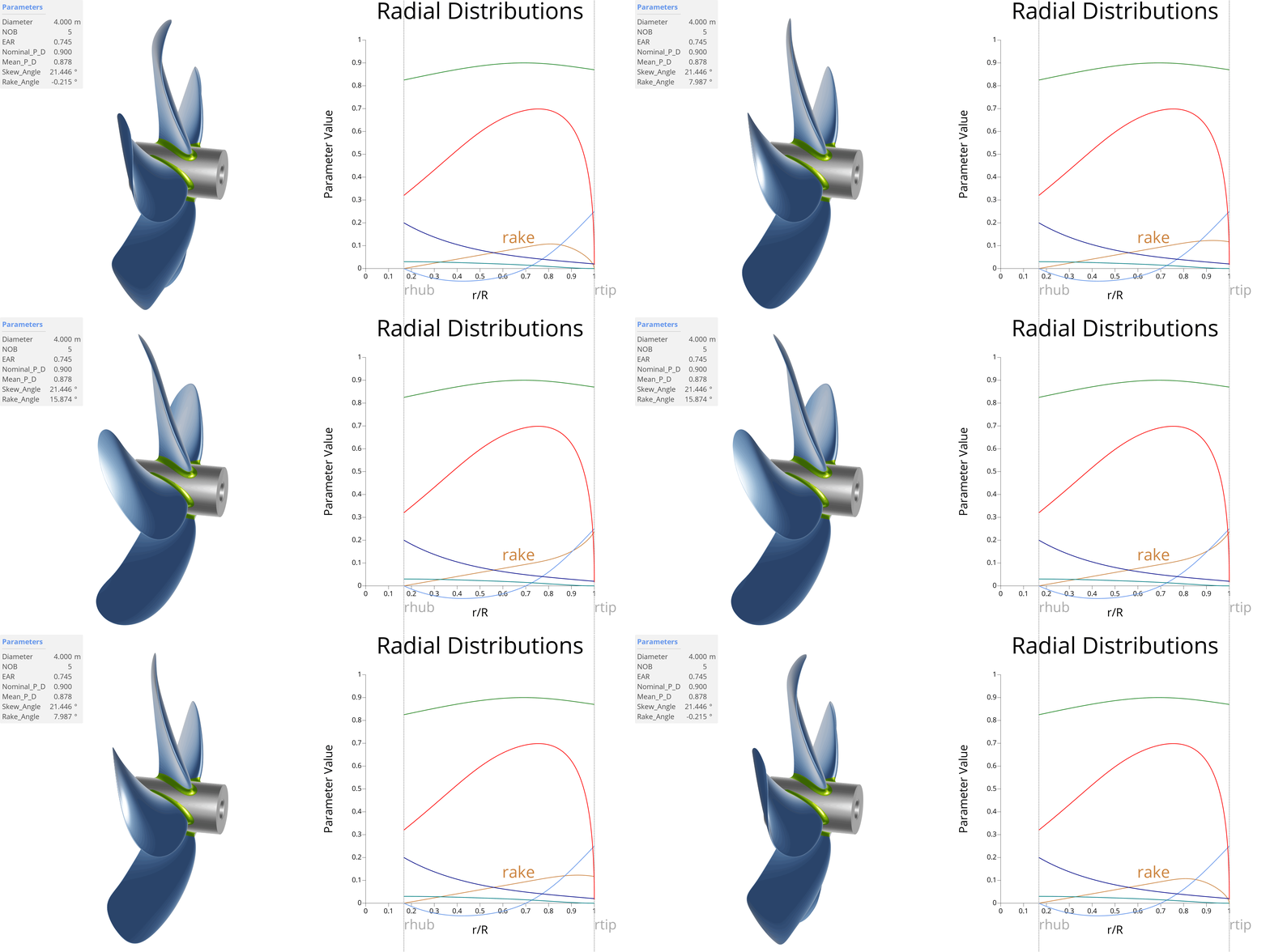
Modern propeller designs often feature non-linear rake distributions, including tip-rake, where the blade bends either forward or backward near the tip, as illustrated in the animation below. The ongoing debate over whether propellers should bend the tip in one direction or the other is closely tied to considerations of blade load and the angle of attack at the propeller tip. The concept of tip-rake in marine propellers, adapted from aviation, primarily serves to reduce noise and manage the tip vortex. By introducing an additional degree of freedom to control the angle of attack near the blade tip, the stream of water can be either contracted or diverged. This adjustment applies to both positive and negative tip-rake designs and significantly affects propeller performance. In marine applications, tip-rake propellers offer potential benefits such as noise reduction, reduced cavitation and potentially increased propeller efficiency [9]. Read more about tip-rake propellers here.
Outlines and Area
Projected Outline
The projected outline refers to the view of the propeller blade as seen from the back. The projected area ( ) is the area of the blade as projected onto a plane perpendicular to the thrust direction. While less emphasized today, it was extensively used in early propeller design to determine the required blade area based on thrust loading per unit projected area to mitigate cavitation effects. A semi-empirical equation provided by Burrill for calculating ( ) is:
Expanded Outline
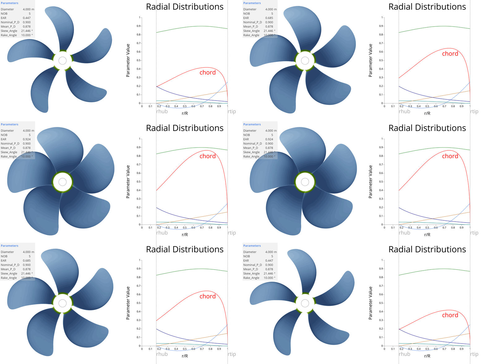
The expanded outline represents the plotting of chord lengths at their correct radial stations. This outline does not attempt to depict the helical nature of the blades and each section's pitch angle is reduced to zero. The expanded area is simply calculated using the formula , where represents the chord length at radius .
Expanded Area Ratio (EAR)
The expanded area ratio ( ) is a crucial term in propeller design, defined as the ratio of the expanded blade area to the propeller’s disk area . This non-dimensional ratio is vital for evaluating propeller performance characteristics, including efficiency, thrust and cavitation risk.
- on Cavitation: A higher expanded area ratio helps reduce cavitation by distributing the load over a larger surface area, thereby lowering the pressure difference on any single point of the blades.
- on Thrust & Drag: Propellers with higher expanded area ratios can generate more thrust, making them suitable for applications requiring high thrust at lower speeds. However, they may also increase drag.
A favorable minimum EAR, according to Keller, for avoiding cavitation is as follows:
The value of in the equation above varies with the number of propellers and ship type as follows:
- for single-screw ships ,
- for twin-screw ships it varies within the range for fast vessels to for the slower twin-screw ships.
Center Surface
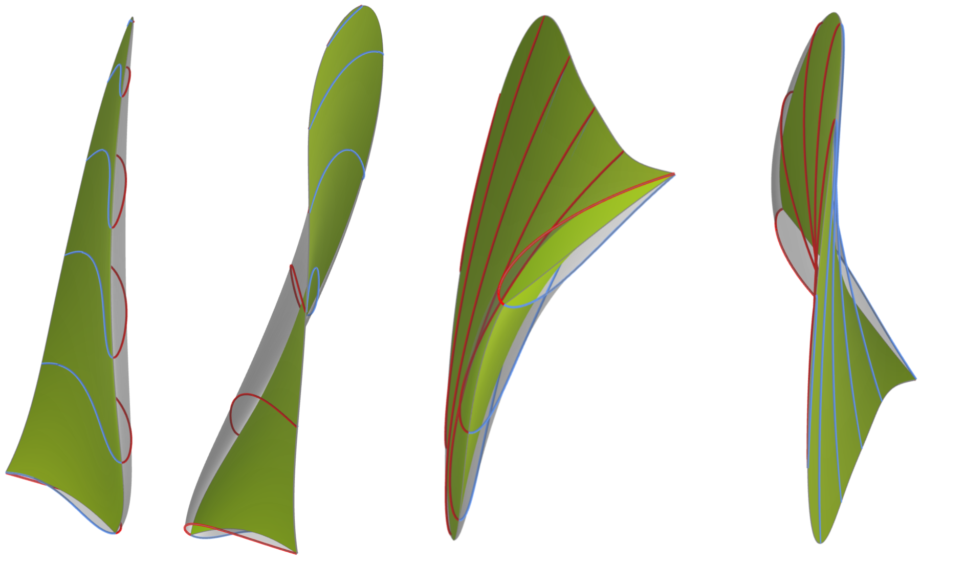
One essential part of marine propeller design in CAESES is the concept of the center surface (shown in green in the figure below). This surface is derived from propeller geometry principles, including pitch, skew, rake, and chord length for each span-wise position. It can be interpreted as the surface formed by the locus of chord lines, extending from the leading edge to the trailing edge along the span of the blade sections. Additionally, it simplifies handling unconventional designs, such as tip-rake and highly skewed propellers, and overcomes the limitations of cylindrical section definitions. The center surface serves as a guide for creating the propeller blade but is not the same as the camber surface.
The camber surface incorporates the camber, while the center surface does not contain any camber information. Based on the center surface and by specifying the thickness and camber of the profile at each span-wise position, the blade is generated, as depicted below in semi-transparent grey color. The blue color represents the suction side of the sections, while the red color represents the pressure side of the sections.