Sweeping Foreship
The sweeping foreship is a component used in the Ship Modeling Workflow which is accessible via the Maritime-Tab (CAESES add-on). It is part of the modeling workflow for the ship type Component-Based. The sweeping foreship is modeled using base curves that are sections at the beginning (aft end) of the foreship and start rotating towards the y-plane further forward. At the end of the foreship, the base curve is equal to the centerplane curve (CPC). The sweeping foreship is most suitable for high blockage ships, such as tankers and bulkers, and can include a bulbous bow in the main surface.
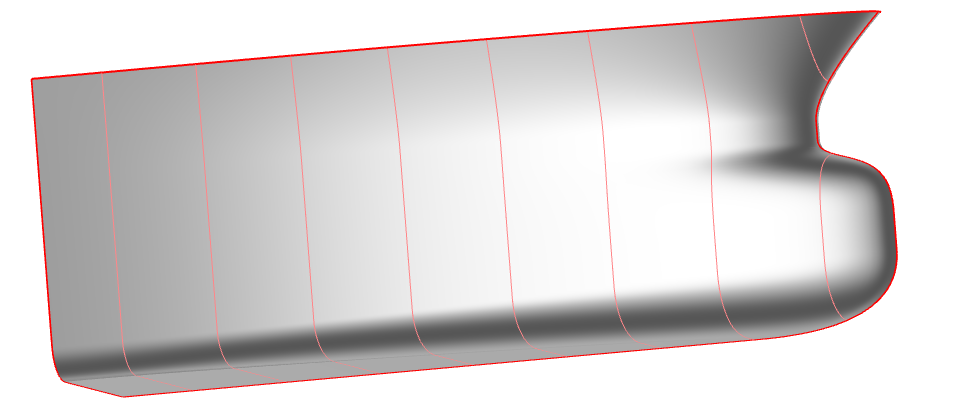
Since the base curve of the main surface rotates from the main frame towards the centerplane curve without accounting for outward-leaning sections, this component cannot represent flare by definition. For foreships with flare, use the Waterline-Based Foreship or the Section-based Foreship instead.
Model Structure
This model follows the same structure as the other models of the Ship Modeling Workflow. It is split into three main scopes:
01_geometryCurves: contains all curves that have a real physical meaning, e.g. deck02_surfaces: contains all surfaces and the functions for meta-surfaces03_brep: contains the final BRep and prior processing steps, i.e. trimming, if necessary
All design variables are located in the scope where they are used. Their names are chosen to be descriptive of their functionality and the bounds are tested for robustness of the model. The Ship Modeling Workflow allows to change any values, object types or the overall model structure for maximum flexibility.
Inputs taken from Ship Modeling Workflow
The main dimensions of the ship and other additional dimensions are provided to this foreship component by the hullParameters component which is set at the ship component.
In addition, the foreship component receives the section at the end of the midship from the midship component.
Geometry Curves
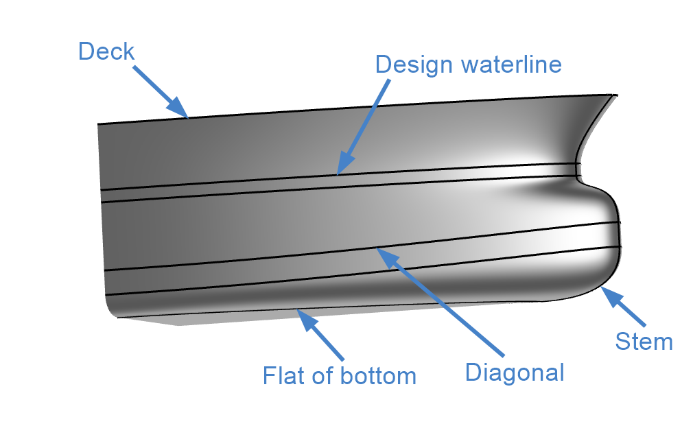
Five geometry curves are needed for the sweeping foreship which are gathered in the scope 01_geometryCurves. The section at the end of the midship, the deck, the design waterline (DWL), a diagonal and the flat of bottom curve.
A second design waterline and a second diagonal can be introduced which are identical to the first curves. This is used to introduce a straight band in the geometry, as it is sometimes used in very full hulls.
The stem is not a real geometry curve, but the last section of the meta surface. However, it is included here since many of the design variables influence the stem curve.
Input from Midship
In the scope 00_fromMidship, the input from the interface of the Ship Modeling Workflow, the end section of the the midship, is split into different sections that are required further down in the model.
Stem
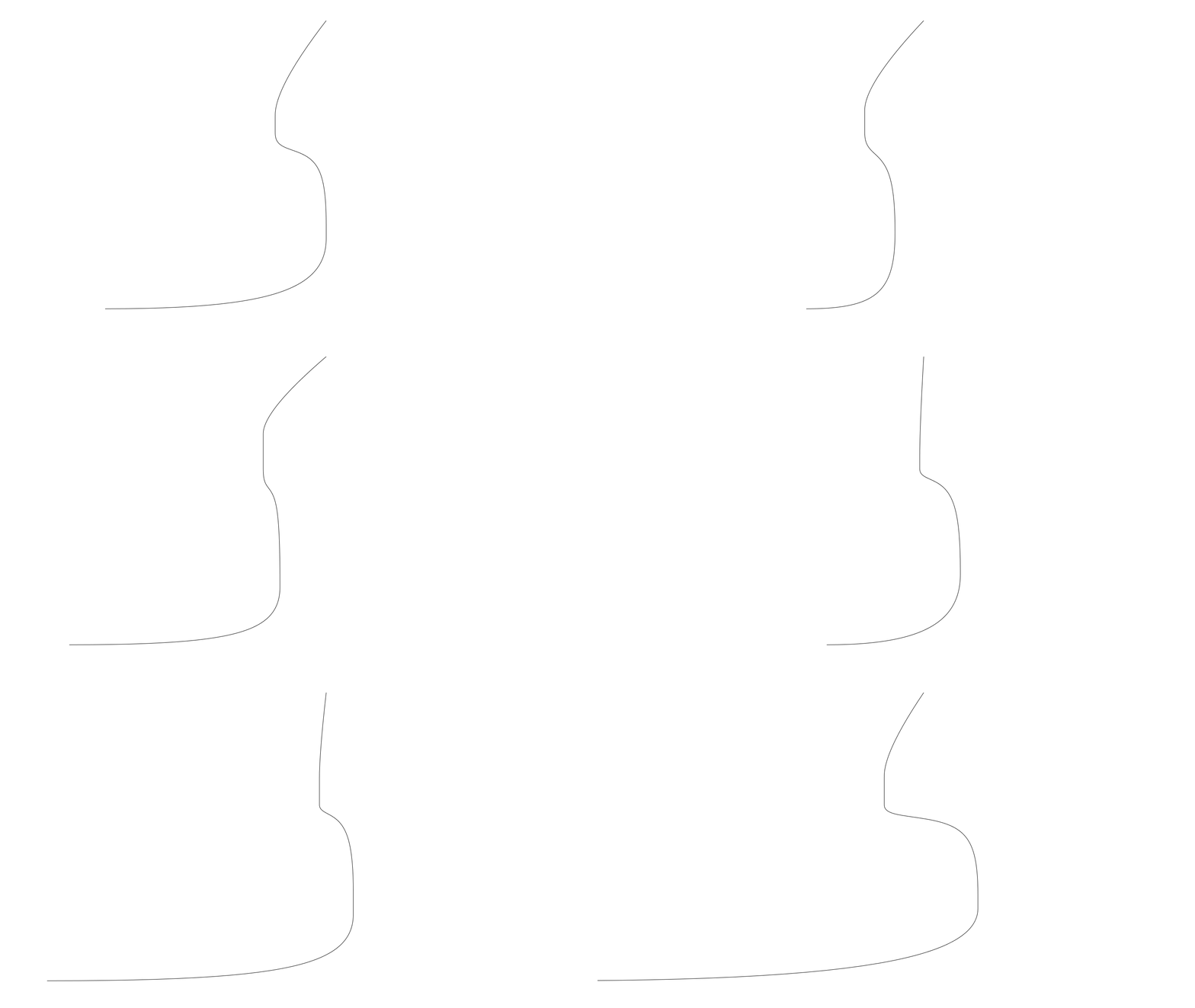
The stem contour (in the scope 01_stemContour) is not an actual geometry curve, but the last section of the meta surface. however, the effect of many design variables can be observed at the stem contour. As for the base curve of the surface, the stem contour is a polycurve consisting out of three NURBS curves and two lines.
-
relXFwrdBase
relative value based on the length of the ship - Specifies the start of the stem, i.e. where the flat of bottom ends. -
relBowOverhangDesignDraft
relative value based on the length of the ship - Specifies the longitudinal distance between the end of the design waterline and the end of the deck curve. -
relBulbLength
relative value based on the length of the ship - Specifies the length of the bulbous bow from the end of the design waterline. -
relBulbTipHeight
relative value based on the draft of the ship - Specifies the height of the foremost point of the bulb, i.e. the end of the diagonal. -
relHeightUpperBand
relative value based on the draft of the ship - Specifies the height of the straight part of the surface above the design waterline. -
relHeightLowerBand
relative value based on the draft of the ship - Specifies the height of the straight part of the surface above the diagonal. -
weightLow
absolute value - Specifies the weight of the middle point of the lower NURBS curve. A higher value will give a sharper rounding. -
weightLow
absolute value - Specifies the weight of the middle point of the upper NURBS curve. A higher value will give a sharper rounding. -
fairingExt
relative value based on the distance between the DWL and the diagonal - Specifies the distance between the last and the second to last point of the upper NURBS curve. A higher value will give a larger rounding below the DWL.
Deck
The deck (in the socpe 02_deck) is modeled using a single NURBS curve with four control points. One design variable is used to control the shape of the deck:
- tanFactotAtStem
relative value based on the half beam of the ship. A larger value gives a rounder deck contour in the forward part. The tangent at the stem is fixed to 90 degrees.
Design Waterline
The design waterline (DWL) is modeled using a NURBS curve with five points (in the scope 03_dwl). A copy of the DWL is moved to fit the upper band height. Three variables are used to control the shape of the DWL:
- DWLentranceAngle
Absolute value describing the tangent of the DWL at FP. - tanFactotAtStem
relative value based on the half beam of the ship. A larger value increases the influence of the entrance angle of the DWL shape. - tanFactotAtFos
relative value based on the length of the DWL. A larger value gives a rounder contour in the aft part.
Diagonal
The diagonal controls the lower part of the forebody (in scope 04_diagonal). In the aft it is identical to the DWL, in the forward part it ends at the bulb tip.
- tanFactotAtStem
relative value based on the half beam of the ship. A larger value results in a rounder shape in the forward part. - trimPositionOfYCompDwl
relative value based on the length of the DWL. A larger value means that the diagonal follows the DWL for a longer time, resulting in a straighter, fuller forebody shape.
Flat of Bottom
The flat of bottom (FOB) is modeled as a NURBS curve and lies in the 05_fob scope. To model deadrise, a generic curve is used with the x and y coordinates of the FOB curve, but the z coordinates of the bottom part of the main frame. Two design variables control the shape of the FOB.
- tanFactotAtStem
relative value based on the half beam of the ship. A larger value results in a rounder shape in the forward part. - tanFactotAtFos
relative value based on the length of the DWL. A larger value gives a rounder contour in the aft part.
Surfaces
The sweeping foreship is formed by one surface which is based on a polycurve consisting of NURBS curves and lines. The base curve starts in the x-plane at the main fram and rotates towards the y-plane as it moves forward. Thus, at the beginning of the surface the base curve is identical to the main frame and at the end of the surface it is identical to the stem curve. Below figure shows the main frame, the stem and three intermediate sections of the surface.
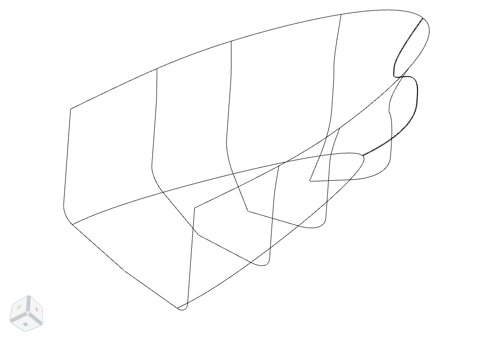
The base curve is built up identically to the Stem curve, with a lower NURBS curve, a line, a middle NURBS curve, a second line and an upper NURBS curve. Additionally, a line to model the flat of bottom is added. The base curve meets the geometry curves FOB, diagonal, DWL and deck. Three additional design variables are used to control the surface:
-
hasKnuckle
integer value of 0 or 1. A value of 0 implies a fairing between the bulb and the upper part, a value of 1 creates a knuckle. -
weightLow/extAft
relative value between 0 and 1. Controls the influence of the weight of the lower point at the bilge on the surface shape. -
weightUpper/weightUpperCurve_atFos
relative value. Controls the weight of the upper point at the start of the surface, i.e. the Fos. -
weightUpper/extAft
relative value between 0 and 1. Controls the influence of the weight at fos on the surface shape.
Final Sweeping Foreship
The final sweeping foreship BRep is identical to the main surface.