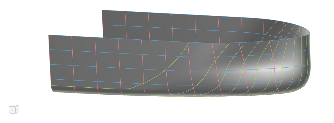
Waterline-Based Foreship
The waterline-based foreship is a component used in the Ship Modeling Workflow which is accessible via the Maritime-Tab (in the CAESES Maritime add-on). It is part of the modeling workflow for the ship type Component-Based. As the name already suggests, the base curves for the generation of the main surface of this model are waterlines running from the flat of side (FOS) to the stem.
Since the main surface is generated from waterlines, this component cannot represent a deadrise by definition. For foreships with deadrise, use the Sweeping Foreship or the Section-based Foreship instead.
Two waterline-based foreships are available within the workflow, one that uses B-Spline curves and one that uses F-Spline curves as base curves for the main surface.
The F-Spline variant has fewer design variable options than the B-Spline variant, which makes the F-spline approach easier to use but also less flexible. The F-Spline version is most suitable for high blockage ships, e.g. tankers.
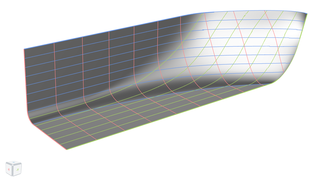
Model Structure
This model follows the same structure as the other models of the Ship Modeling Workflow. It is split into three main scopes:
01_geometryCurves: contains all curves that have a real physical meaning, e.g. stem02_surfaces: contains all surfaces and the functions for meta-surfaces03_brep: contains the final BRep and prior processing steps, i.e. trimming, if necessary
All design variables are located in the scope where they are used. Their names are chosen to be descriptive of their functionality and the bounds are tested for robustness of the model. The Ship Modeling Workflow allows to change any values, object types or the overall model structure for maximum flexibility.
Inputs taken from Ship Modeling Workflow
The main dimensions of the ship and other additional dimensions are provided to this foreship-component by the hullParameters-component which is set at the ship-component.
In addition, the foreship-component receives the section at the end of the midship from the midship-component.
Geometry Curves
Three geometry curves are needed for the waterline-based foreship. The section at the end of the midship, the flat of side (FOS) curve and the stem.
The flat of bottom (FOB) does not need to be modeled because it is implicitly created with the main surface as it is the waterline at a depth of zero meters.
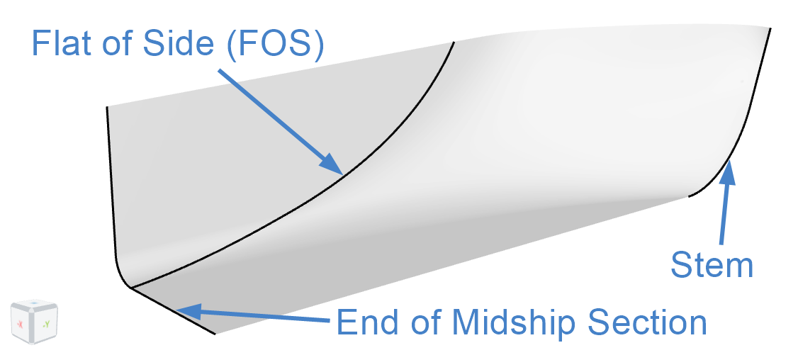
Input from Midship
In the scope 00_fromMidship, the input from the interface of the Ship Modeling Workflow, the end section of the midship, is split into different sections that are required further down in the model.
Flat of Side Curve
The flat of side (FOS) is modeled in the scope 01_fos. For modeling reasons, the flat of side curve does not start at the top of the bilge but at the bottom of it. The shape of the FOS can be changed with one design variable:
angleAtDeck- Absolute value in degrees
- A value of 0° corresponds to a vertical entry of the FOS at the deck
relXEnd- Relative value based on the ship length - A value of 0.8 corresponds to the FOS end being at 80% of the ship length, measured from the aft perpendicular

Stem

The stem (in scope 02_stem) is split into a lower and an upper part at the height of the design waterline. Two design variables are implemented to control the stem shape:
stem_overhangAtDWL- Absolute value in meters
- Controls the distance between the maximum length point (end of the deck curve) and the stem at the design waterline (DWL)
- Can be positive or negative
relXFwrdBase- Relative value based on the maximum length point
- Controls the x-coordinate of the start of the stem
stemTangentAtDwl- Absolute value in degrees
- Controls the the angle of the stem at the design draft
- A value of 0° corresponds to a vertical stem
weightMidLow- Absolute value
- Controls the weight of mid point of the NURBS curve which is used for the lower part of the stem
Surfaces
The waterline-based foreship is formed by one main surface which is a Meta Surface with the base curve being a waterline. This section visualizes the variability of the implemented waterline and explains how the existing design variables vary the shape of the main surface.
Main Surface (F-Spline)
The setup for the main surface of the foreship can be found in the scope 01_mainSurf.
Curve Engine
The base curve of the curve engine is a F-spline curve. The waterline entrance angle at the stem is fixed to 90 degrees, i.e. a blunt waterline. Two parameters are implemented to change the shape of the waterline:
- Curvature radius at stem
- Absolute value to control the curvature of the waterlines at the stem
- A larger value gives a fuller waterline
- Waterline fullness
- relative value to control the area under the curve
- A value of 1 corresponds to the value the curve would have without the area input, i.e., the natural area of the F-Spline
- Larger values produce fuller waterlines
Main Surface (B-Spline)
The setup for the main surface of the foreship can be found in the scope 01_mainSurf.
Curve Engine
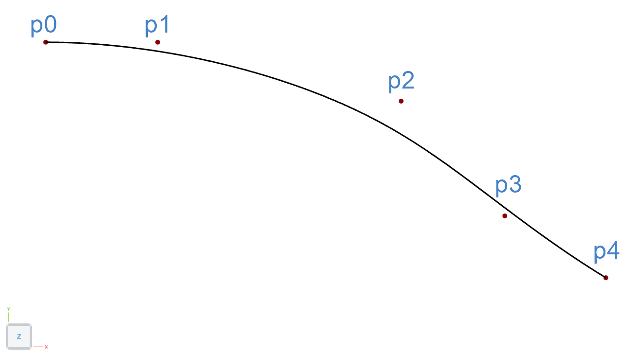
The base curve of the curve engine is a B-Spline curve with five control points. p0 lies on the FOS and p4 on the stem. p1 and p3 provide the tangent at the corresponding curve. Point p2 has the most influence on the shape of the B-Spline curve.
Five parameters are implemented to change the shape of the waterline:
- Tangent Factor At FOS
- Relative value to control the x-position of point p1 between p0 and p4
- A value of
0corresponds to p1 being on the FOS - A value of
1to have the same x-coordinate as the stem

- Tangent Factor At Stem
- Relative value to control the distance from p3 to p4
- A value of
0corresponds to p3 being directly on p4 - For a value of
1the distance is exactly half the beam of the ship

- Waterline Angle
- Absolute value in degrees
- For a value of 0°, p3 and p4 have the same y-coordinate
- For a value of 90°, p3 and p4 have the same x-coordinate
- Waterline Shape X
- Relative value to control the x-position of p2
- Same x-coordinate as the end of the FOS, for a value of
0 - Same x-coordinate as the maximal x-coordinate of the ship for a value of
1

- Waterline Shape Y
- Relative value to control the y-position of p2
- Point p2 has the same y-coordinate as p4 for a value of
0. - Point p2 has the same y-coordinate as p0 for a value of
1.
Functions
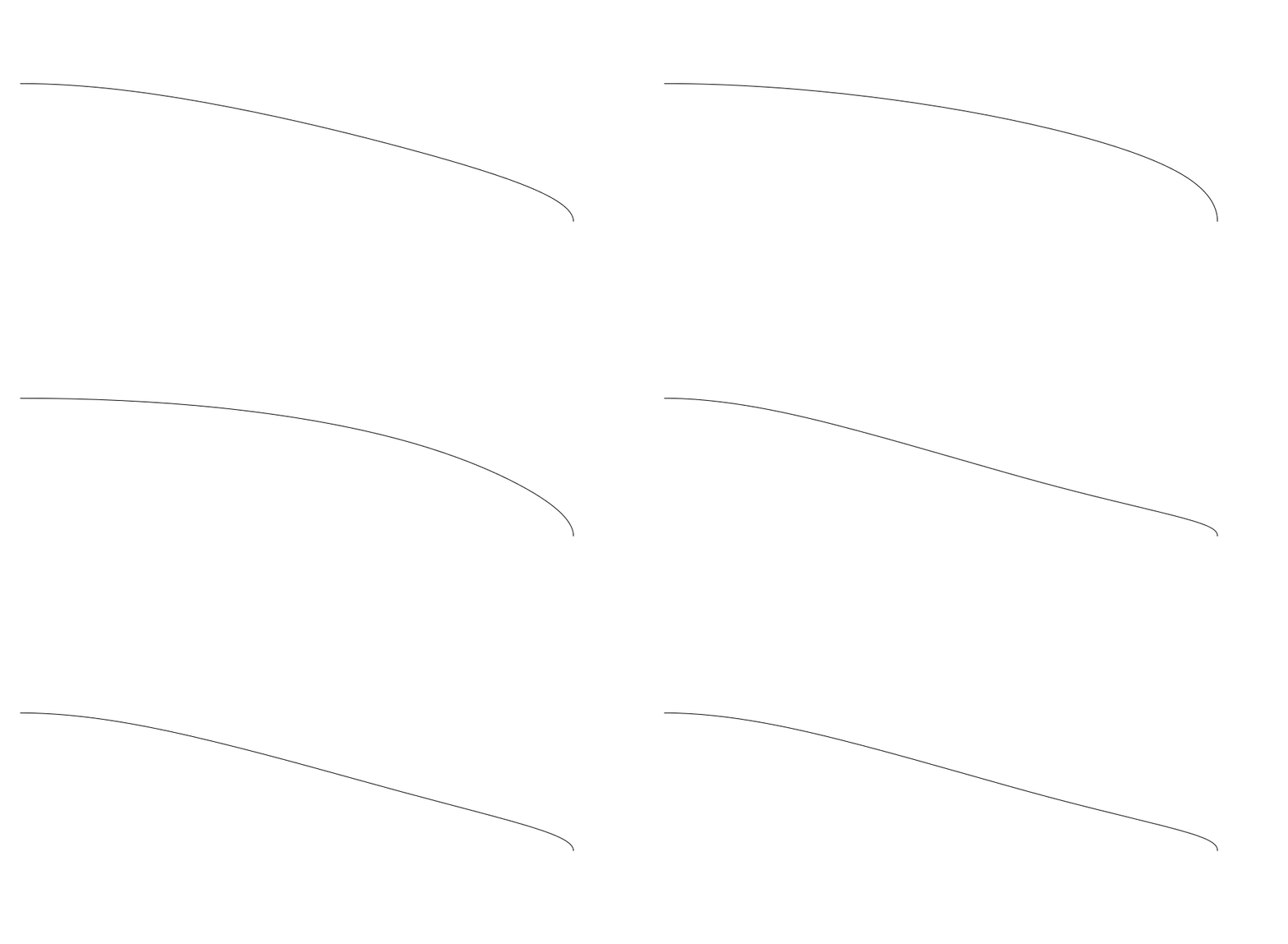
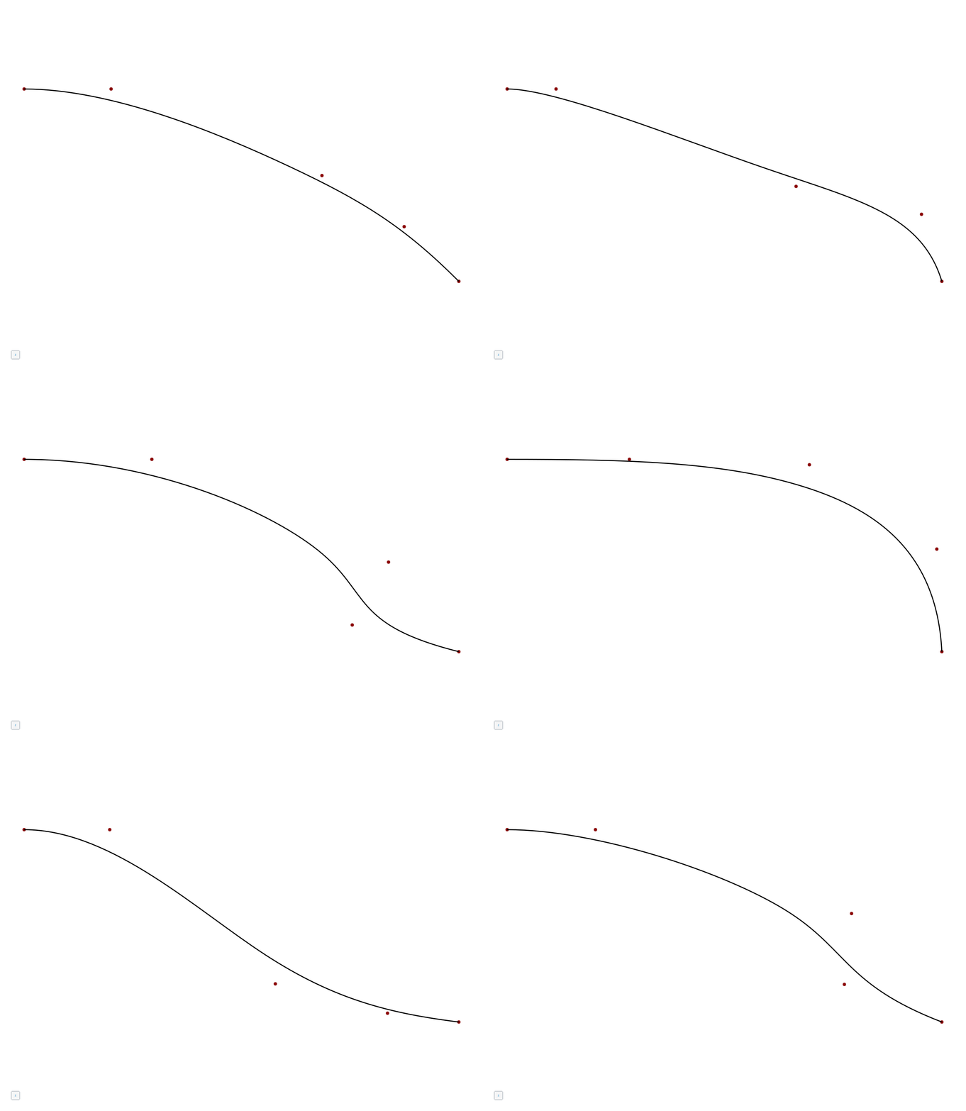


For the specification of any waterline over the ship's depth, functions are introduced for the parameters of the base curve. In the animations below, the implemented design variables for the different functions are visualized.
| Functions | Waterlines |
|---|---|
 |  |
 |  |
| Waterline Shape X - constant value over the depth of the ship |  |
 |  |
Flat of Side Surface
The flat of side (FOS) surface is created in the 02_fos scope using a feature that projects the input curve onto a plane and then generates a Ruled Surface between the input curve and the projected curve.
Flat of Bottom Surface
For the flat of bottom (FOB) surface in scope 03_fob, the same feature as for the FOS surface is utilized.
Final Waterline-Based Foreship
The final BRep in scope 03_brep combines the surfaces main, fob and fos to form the waterline-based foreship component.