Basic Bulb
The basic bulb is a component used in the Ship Modeling Workflow which is accessible via the Maritime-Tab, a CAESES add-on. It is part of the modeling workflow for the ship type Component-Based, a component-based ship type.
Introduction
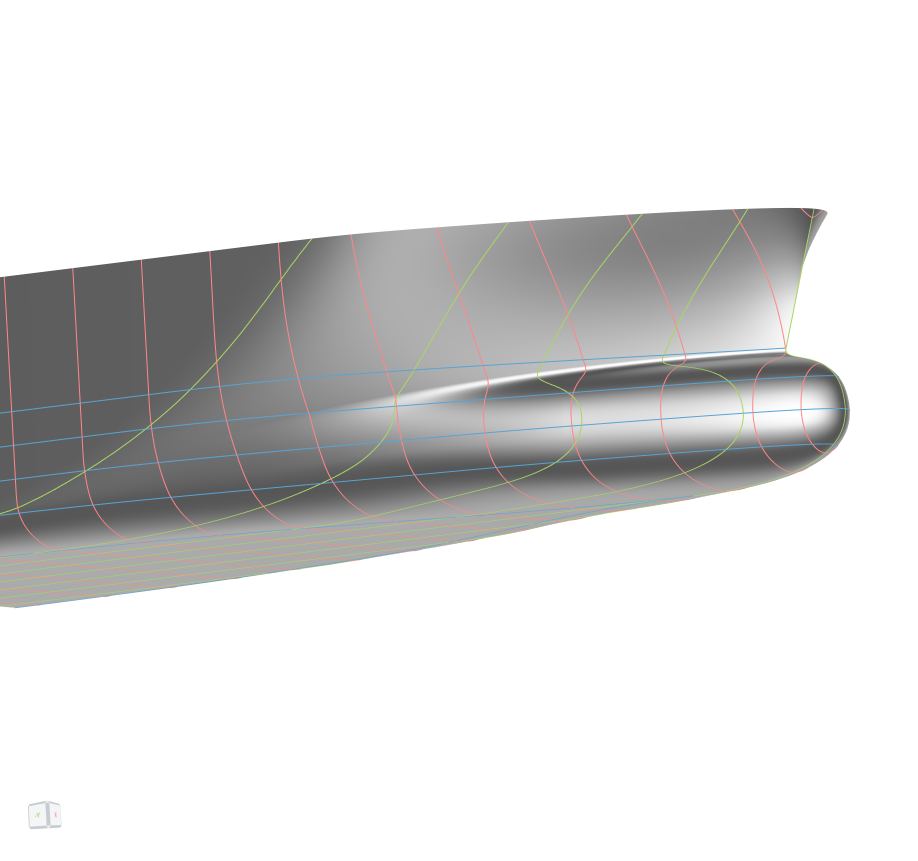
The basic bulb can be used with any forebody and represents a bulbous bow. It is automatically faired into the existing forebody. The model is built using NURBS Curve sections that rotate to the centerline in the front, in order to control the centerline shape of the bulbous bow.
Model Structure
This model follows the same structure as all other models of the Ship Modeling Workflow. It is split into three main scopes:
01_geometryCurves: contains all curves that have a real physical meaning, e.g. the upper rail and the flat of bottom02_surfaces: contains all surfaces and functions for meta-surfaces03_brep: contains the final BRep and prior processing steps, i.e. trimming, if necessary
All design variables are located in the scope where they are first used. Their names are chosen to be descriptive of their functionality and the bounds are tested for robustness of the model. The Ship Modeling Workflow allows to change any values, object types or the overall model structure for maximum flexibility.
Inputs provided through the interface of the Ship Modeling Workflow
Some ship dimensions, including the main dimensions, are provided to the bulb by the hullParameters-component.
The second input is a BRep of the complete forebody.
Geometry Curves
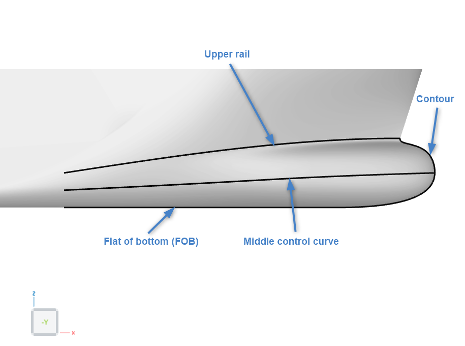
Three geometry curves are needed for the bulb. The upper rail curve, the flat of bottom curve (FOB) and the controlMid curve.
A folder named "contour" is included in the 01_geometryCurves folder. While the contour is not an actual geometry curve but the last section of the meta surface, the folder includes parameters and variables to control the shape of the bulb at the forward end.
Upper Rail Curve
The upper rail curve is modeled in the scope 00_upperRail_cutCurve and represents the upper end of the bulbous bow surface, i.e. the curve where the forebody is cut away and the bulbous bow is inserted.
The shape of the upper rail can be controlled by four design variables:
-
relLengthStart- Relative value based on the distance between start of the forebody and FP (Forward Perpendicular).
- A value of
0corresponds to a horizontal entry of the upper rail at FP.
-
tanCutCurveAtFP- Absolute value in degrees.
- A value of
90degrees corresponds to the upper rail being horizontally at FP.
-
zCutAft_relDraft- Relative value based on the draft of the ship.
- A value of
1means that the start of the upper rail is at the height of the draft.
-
zCutFP_relDraft- Relative value based on the draft of the ship.
- A value of
1means the end of the upper rail (i.e. where it intersects the stem) is at the height of the draft.
Flat of Bottom Curve
The flat of bottom curve (FOB) is modeled in the scope 01_fob. The start of the flat of bottom is at the same x-position as the start of the upper rail and the start tangent is derived from the lower edge of the forebody BRep.
The shape of the flat of bottom can be controlled by one design variable:
bulbFwrdBase_relXPeak- Relative value based on the xPeak position, i.e. the foremost position of the hull.
- A value of
1means that the flat of bottom runs all the way to the maximum x-position of the hull.
Middle control curve
The middle control curve is modeled in the scope 02_controlMid and represents the position of the mid points of the bulb sections. The curve is a B-Spline curve with five points, the start point, the start tangent point, an intermediate point, the end tangent point and the end point.
The shape of the middle control curve can be controlled by four design variables:
-
zBulbTip_relZCut- Relative value based on the height of the end of the upper rail.
- A value of
0.5corresponds to the bulb tip being at half the height of the end of the upper rail.
-
extFactFwrd- Relative value based on the maximum beam of the forebody.
- A value of
0.5corresponds to the end tangent point being at a y-position equal to half the beam of the forebody.
-
tanFactAft- Relative value based on the distance between the start of the upper curve and the bulb tip.
- A value of
0.5means that the start tangent point is positioned at an x-position in the middle between the upper rail start and the bulb tip.
-
deltaAtTwoThird_rel- Relative value based y-position of the start tangent point.
- A value of 0 puts the intermediate point on a curve connecting the start tangent and the end tangent points. Negative values will move the intermediate point inwards, positive values outwards.
Contour
The variables and parameters controlling the contour of the bulb are included in the folder 03_contour. While the bulb contour is also the last section of the bulb Metasurface, it is not technically a geometry curve. However, due to the importance of the bulb contour it is included in the geometry curves.
The shape of the contour can be controlled by six design variables:
-
relBulbLength- Relative value based on length over all of the hull.
- A value of
0.02corresponds to a bulb length of 2% of the length over all.
-
hasKnuckle- Integer value (
0or1) - A value of
0means that the bulb surface has tangent consistency at the upper rail, a value of1means that a knuckle might appear at the upper rail.
- Integer value (
-
weightLowerFwrd- Absolute value.
- Specifies the weight of the lower point. A value of
1corresponds to the weight of the start and end points, higher values increase the influence of the lower point, lower values decrease the influence.
-
weightUpperFP- Absolute value.
- Specifies the weight of the upper point. A value of
1corresponds to the weight of the start and end points, higher values increase the influence of the lower point, lower values decrease the influence.
-
extensionFairingFP- Relative value based on the distance between upper rail and middle control curve.
- A value of
0.5puts the fairing point in the middle of the upper rail and the middle control curve.
-
dzUpperAtTip- Relative value based on the distance between upper rail and the bulb tip.
- A value of
0.5puts the upper point in the middle of the upper rail and the bulb tip.
Surfaces
The basic bulb consists out of three surfaces, where the two main surfaces share the same definition and are only created to ensure a good parametrization of the bulb surface, given the rotating sections in the forward end. In a pre-processing step, the flat of side and flat of bottom faces of the forebody are detected and extracted from the BRep.
Main Surface
The base curve of the main surface is a non-planar section modeled as a poly curve out of two NURBS curves and a fillet curve ensuring curvature consistency between the upper and lower part. The base curve starts off in the x-plane, but is then based on the t-values of the upper rail, middle control curve and the flat of bottom. Additionally, a blending is implemented, ensuring that the section at the start (aft end) of the bulb surface is equal to the forebody shape at this position.
The lower section has three control points:
- The start point on the flat of bottom.
- The lower point ensuring the correct tangent at the bottom.
- The end point aon the middle control curve.
The upper section has four control points (only three, if hasKnuckle is equal to one):
- The start point on the middle control curve.
- The upper point.
- The upper fairing point ensuring tangent consistency between the forebody and the bulb.
- The end point on the upper rail.
The main surface can be controlled by 5 parameters:
-
Y- tangent
- Absolute value in degree, specifying the tangent of the section at the middle control curve in the y-plane.
- A value of
0corresponds to a vertical shape of the section.
-
X- tangent
- Absolute value in degree, specifying the tangent of the section at the middle control curve in the x-plane.
- A value of
90corresponds to a vertical shape of the section.
-
Z Upper
- Absolute value in meter, specifying the z-position of the upper point.
- The value at the end is controlled by the variables in the
03_contourfolder. - The value at the start is set to be in the middle between the upper rail and the middle control curve.
-
Weight lower
- Absolute value.
- Specifies the weight of the lower control point.
-
Weight upper
- Absolute value.
- Specifies the weight of the upper control point.
-
Extension factor fairing
- Relative value based on the distance between upper rail and middle control curve.
- Specifies the position of the upper fairing point.
Flat of Bottom
The flat of bottom (FOB) surface is created in the 03_fob scope using a feature that projects the input curve onto a plane and then generates a Ruled Surface between the input curve and the projected curve.
Final Foreship with Bulb
The final BRep in scope 03_brep combines the surfaces main, fob, the forebody BRep without the planar faces and cut with the upper rail and the planar faces, where the bottom face is cut with the start position of the bulb surface.