Twin Skeg
The twin skeg is a component used in the Ship Modelling Workflow which is accessible via the Maritime-Tab, a CAESES add-on. It is part of the modeling workflow for the ship type Component-Based, a component-based ship type.
Introduction
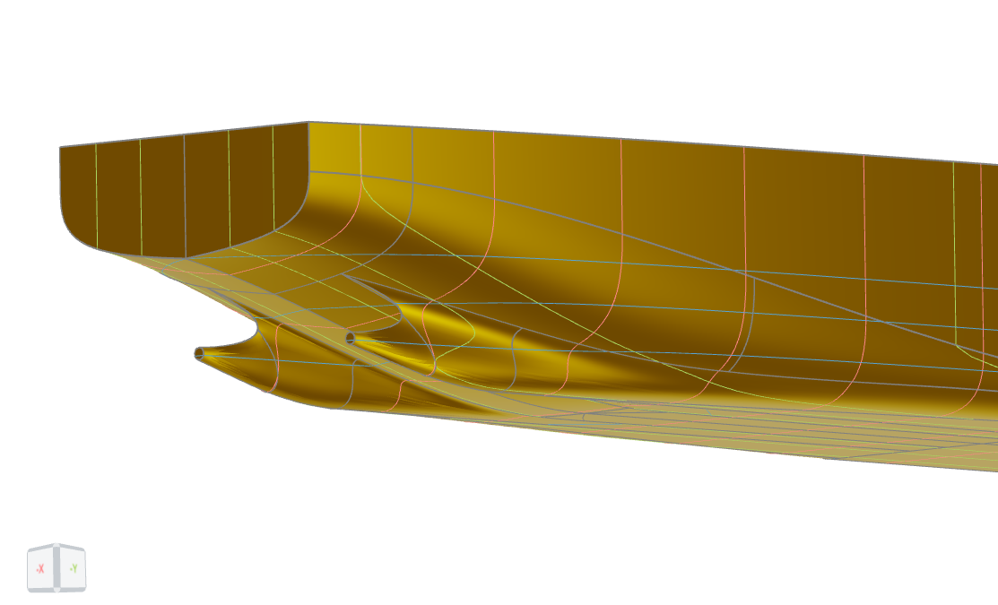
The twin skeg can be used with any aft body, similarly to the single skeg. It is automatically faired into the existing aftbody. The model is built using B-Spline curve sections (modeled in the x-plane) and fairings in the hub region.
Model Structure
This model follows the same structure as all other models of the Ship Modeling Workflow. It is split into three main scopes:
01_geometryCurves: contains all curves that have a real physical meaning, e.g. the upper rail and the flat of bottom02_surfaces: contains all surfaces and functions for meta-surfaces03_brep: contains the final BRep and prior processing steps, i.e. trimming, if necessary
All design variables are located in the scope where they are first used. Their names are chosen to be descriptive of their functionality and the bounds are tested for robustness of the model. The Ship Modeling Workflow allows to change any values, object types or the overall model structure for maximum flexibility.
Inputs provided through the interface of the Ship Modeling Workflow
Some ship dimensions, including the main dimensions, are provided to the twin skeg by the hullParameters-component.
The second input is a BRep of the complete aftbody.
Geometry Curves
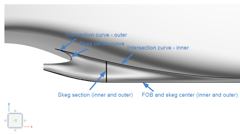
Six geometry curves are needed for the skeg. The intersection curves between the skeg and the aftship (inner and outer), the flat of bottom curves (FOB - inner and outer) and the skeg center curve.
A folder named "skeg section" is included in the 01_geometryCurves folder. While the skeg sections are not actual geometry curves but sections of the meta surfaces which serve as reference sections, the folder includes parameters and variables to control the shape of the skegs.
Skeg Center Curve (lower)
The lower skeg center curve is modeled in the scope 00_skegCenterAndHub and represents the curve where the inner and outer side of the skeg meet, including the the hub. Additionally, the skeg vertical and longitudinal angle curves are defined in this folder.
The skeg angles are controlled with two variables:
-
longitudinalSkegAngle- Absolute value (degrees) corresponding to the longitudinal inclination of the skegs.
- A value of 0 degrees represents straight skegs, positive values presents toe out, i.e. the skegs going outside seen in the forward direction of the skegs.
-
verticalSkegAngle- Absolute value (degree) corresponding to the vertical inclination of the skegs.
- A value of 0 degrees represents straight skegs, positive values present a skeg that is leaning inwards on the upper parts.
The skeg center curve is controlled with parameters from the ship main dimensions (z and y position of the boss and the hub diameter) and one design variable:
aftBase_relXEnd- Relative value based on the distance between the x-position of the boss and the end of the aftship.
- A value of 0.05 means that the flat part (FOB) starts at 5% of the distance between the x-position of the boss and the end of the aftship forward of the boss.
Flat of Bottom Curves
The flat of bottom curves (FOB) are modeled in the scope 01_fob. The start of the flat of bottom is at the aft base position, defined in 00_skegCenterAndHub
The shape of the flat of bottom curves can be controlled by two design variables:
-
yPosFobEndOutside_relBeam- Relative value based on the beam of the ship.
- A value of 0.8 means that the flat of bottom on the outside ends at a y-position of 80% of the ships beam.
-
fullnessFob- Relative value controlling the area of the flat of bottom curve on the outside based on the surrounding rectangle.
- A value of of 0.5 corresponds to the curve having 50% of the area compared to the rectangle defined by the length and width of the curve.
Additionally, a parameter yrel_yPosEnd_inside is found in the folder which is a relative value based on the beam of the ship controlling the y position of the end of the inner flat of bottom curve. The start tangents of the flat of bottom curves are equal to the longitudinal skeg angle and the end tangent are set to zero.
Intersection Curves
The intersection curves are modeled in the scope 02_intersectionCurves and represents the upper end of the skegs, i.e. the position where the aftship is cut and the skegs are attached. The curves are defined as b-spline curves with four points. Apart from the start and end points, two intermediate points control the shape of the curve. The second point can be controlled in the longitudinal and transversal direction, the third point i located at the same y-position as the end point and in between the second and end point.
The shape of the intersection curves can be controlled by two design variables each. The variable definitions are identical for the inner and outer curve.
-
extensionFactor- Relative value based on the x-position of the boss and the end of the aftship.
- A value of 0.5 corresponds to the second point being in the middle between the start and the end of the curve, lower values move the point aft and create a fuller curve.
-
offsetMid- Absolute value.
- A value of 0 means the second point is at the same y-position as the end point. Positive values move the point away from the skeg center (outwards on the outer intersection and inward for the inner intersection).
Skeg Section
The variables and parameters controlling the skeg sections are included in the folder 03_skegSection. The skeg sections are not technically geometry curves, but are used as reference section to control the shape of the skegs. The skegs are defined using two B-Spline curves, one for the outside and one for the inside. Each curve is defined using five points, the start and end points, points for the upper and lower tangents and an intermediate point to control the roundness.
The shape of the skeg sections can be controlled by two sets of identically defined sets of three design variables:
-
lowerExtensionFactor- Relative value based on the horizontal distance between intersection and fob curve assuming a vertical skeg angle of 0 degrees.
- A larger values gives a wider, more rounded skeg in the lower part.
-
uppperExtensionFactor- Relative value based on the horizontal distance between intersection and fob curve assuming a vertical skeg angle of 0 degrees.
- A larger values gives a more slender skeg in the upper part, with a more hollow clearance curve.
-
roundnessFactor- Relative value based on the positions of the second and fourth points of the skeg section.
- Controls the y-position of the third point of the section. A higher value leads to a more round, less pear-shaped section.
Skeg Center Curve (upper)
The variables and parameters controlling the upper skeg center curve are included in the folder 04_skegCenterCurve. The upper skeg center curve controls the clearance in front of the propeller and the connection between the inner and outer part of the skeg.
The shape of the skeg center curve can be controlled by two design variables:
-
extensionFactMid- Relative value based on the length of the skeg.
- A larger values gives a more pronounced, i.e. longer, clearance curve, especially in the middle part, at the height of the hub.
-
extensionFactUpper- Relative value based on the length of the skeg.
- A larger values gives a more pronounced, i.e. longer, clearance curve, especially in the upper part, close to the hull.
Surfaces
The twin skeg consists of seven surfaces. The main surfaces on the inside and outside share similar definitions and are divided into a forward and aft part only created to ensure a good fit between the skeg and the hull by means of a blending and to reduce the control points of the aft part which is favorable for the modification to match the skeg center curve. The surfaces are found in the folder 02_surfaces.
Main Surfaces
The main surfaces on the inside and outside are defined as Meta Surfaces with the skeg section as base curve. The control points of the aft parts of the surfaces are modified to match the upper skeg center curve.
Apart from the variables in the 03_skegSection folder, the shape of the main surfaces can be controlled using two variables (nafLowerExtCurve_outside and nafUpperExtCurve_outside) defining area of the curves controlling extension factors along the length of the skegs.
To achieve a good transition to the midship, the main surfaces include a blending which blends from the skeg definition to the bare hull curve towards the end of the aftship.
Hub Fairing
The hub fairing on the inside and outside ensure that the aft of the skegs match the hubs and are placed in 02_hubFairing.
The hub fairings are based on b-spline curves running from a cut curve on the main surface on the outside and the aft inside surface. The cut curve is defined as a circle which radius is based on the length of a projection curve of the hub on the main surface, to ensure that the shaft would not cut the surface. The surfaces are defined by the hub diameter and the shape of the outside and inside of the skeg.
Flat of Bottom
The flat of bottom (FOB) surface is created as a BRep from a closed loop using the flat of bottom curves of the skeg.
Final Foreship with Skegs
The final BRep in scope 03_brep combines the surfaces of the skeg and the aftbody BRep, trimmed using the intersection curves.