Profile Section Geometry
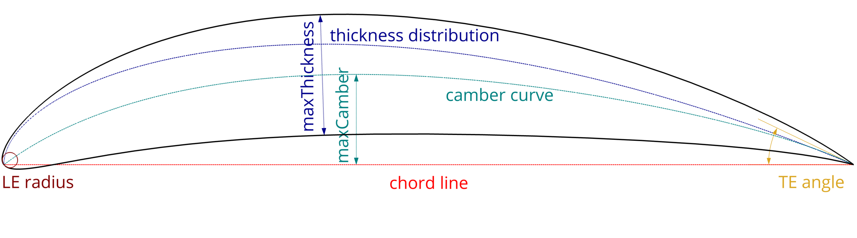
The following figure depicts the geometric features of a propeller blade section with a sharp trailing edge (TE), highlighting various key parameters [7]:
- Chord Line: The straight line connecting the leading edge (LE) and trailing edge (TE) of the profile.
- Camber Curve: An imaginary line which lies halfway between the upper and lower side of the airfoil and intersects the chord line at the leading and trailing edges.
- Max. Camber: The maximum distance between the camber curve and the chord line.
- Max. Camber Pos.: The position along the chord line where the maximum camber occurs.
- Thickness Distribution: The distribution of thickness which is added as an offset in normal direction to the camber curve to form the upper and lower side of the profile.
- Max. Thickness: The maximum distance between the upper and lower side of the profile. The maximum thickness value lies where the thickness distribution reaches it's maximum.
- Max. Thickness Pos.: The position along the chord line where the maximum thickness occurs.
- Leading Edge (LE) Radius: The radius of the leading edge curvature refers to the size of the rounded curve at the front of an airfoil or propeller blade.
- Trailing Edge (TE) Angle: The angle formed at the trailing edge relative to the chord line.
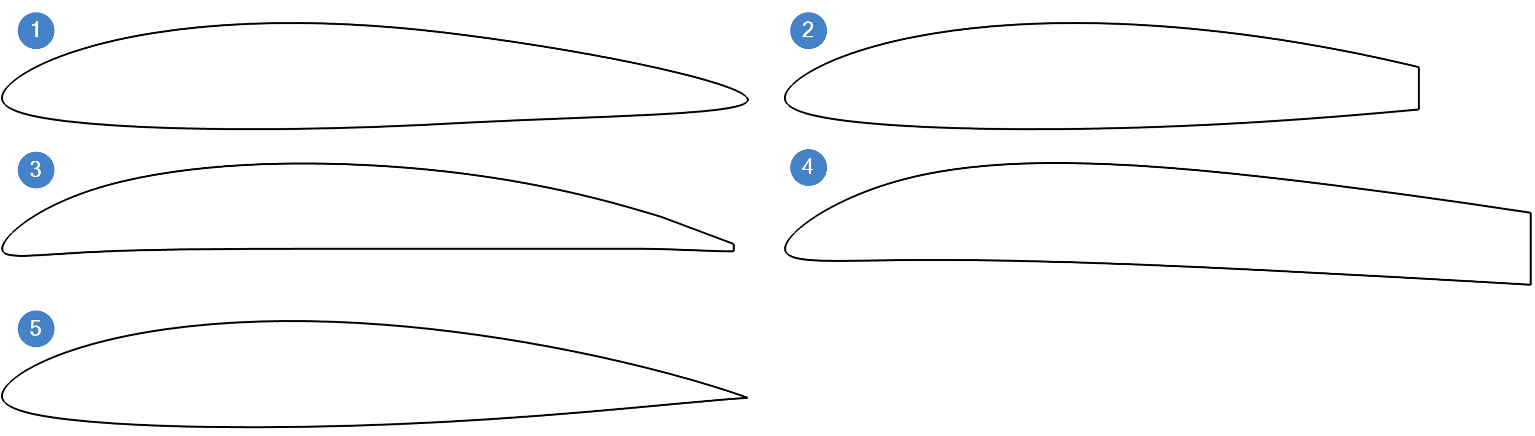
Different Trailing Edge Types
- Rounded: More typical one. Smoothly curved, forming a round shape. Reduces flow separation and noise but can be challenging to manufacture.
- Truncated: Cut off or squared, creating a flat end. Easier to produce and provides controlled flow separation but can increase drag and noise.
- Anti-singing: Specifically designed to reduce high-pitched noise caused by vortex shedding. Improves the acoustic profile but can be complex to design and implement.
- Blunt: Used in surface piercing propellers, usually with maximum thickness at the trailing edge and a flat end.
- Sharp: Not realistic but used in BEM theory to ensure zero pressure difference at the TE (Kutta Condition).
NACA 4-Digit
The NACA 4-digit series (NACA 4DS) is a set of airfoil shapes that describes the cross-sectional geometry of the airfoil. Each airfoil is designated by a four-digit code that encapsulates key geometric properties:
- First Digit: Maximum camber as a percentage of the chord length.
- Second Digit: Position of the maximum camber from the leading edge in tenths of the chord.
- Third and Fourth Digits: Maximum thickness of the airfoil as a percentage of the chord length.
NACA 6-Series
The NACA 6-series airfoils were developed to achieve low drag and high critical Mach numbers while maintaining extensive laminar flow at high Reynolds numbers. These designs focused on practical extents of laminar flow, balancing low drag and robustness against rough surface conditions.
NACA 66 Airfoil: In the designation NACA 66, the second 6 signifies that the position of minimum pressure is at 60% of the chord length from the leading edge.
NACA 66 Mod a=0.8 in Marine Propellers
The NACA 66 mod a=0.8 airfoil is specifically designed for marine propeller applications [8]. The parameter a = 0.8 indicates that the airfoil provides constant lift over the first 80% of the chord, with a linear decrease to zero at the trailing edge. This configuration helps reduce cavitation and enhances propeller performance. The modification (mod) involves thickening the edge region of the NACA 66 section to withstand mechanical damage, as the original thin edges of NACA sections were vulnerable to such damage in marine environments.