Propeller Design Workflows in CAESES
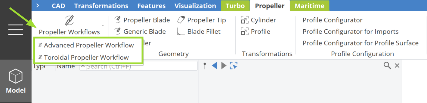
The Propeller Workflows in CAESES offer a wide range of specialized components and a comprehensive, step-by-step guide for creating a fully-parametric propeller model. The workflow can be accessed in the Propeller workspace, like shown in the figure below.
Upon clicking, two options will appear: Advanced Propeller Workflow and Toroidal Propeller Workflow, as the design process for these two types of propellers differs slightly.
For background on propeller design fundamentals, see:
- Blade Geometry — pitch, rake, skew, and expanded area ratio
- Profile Section Geometry — blade cross-section parameterization
- Types of Propellers — conventional, toroidal, tip-rake, rim-driven thruster, and more
- Propeller Optimization — CFD-driven multi-objective optimization for efficiency, cavitation, and noise
- Computational Methods — BEM and RANS approaches for propeller analysis
These two workflows effectively organize the design process, starting with the definition of a Center Surface, where you specify parameters such as pitch, rake, skew and chord. Next, the workflow guides you through the creation of a Profile Configurator, which allows for defining the Camberline and Thickness Curve using various methods, including NACA modifications. The configurator also supports Importing Profiles, providing flexibility in profile curve design. The propeller design workflow continues with the creation of the Blade Surface and Tip Surface, ensuring a structured approach to propeller modeling. In the final stages, you will construct the Propeller Solid, which includes the Variable Radius Fillet and Full-Bladed Geometry, before generating a Flow Domain.
This intuitive, wizard-like approach is designed to assist both novice and experienced propeller designers by simplifying the selection and application of propeller-specific features available within the PropellerThis functionality requires the Propeller add-on to be enabled. add-on. It ensures that the project structure remains organized and coherent, significantly accelerating the modeling process.
Step 1 | Define a Center Surface
An essential part of propeller design in CAESES is the concept of the Center Surface (shown in green in the figure below). This surface is derived from propeller geometry principles, including pitch, rake, skew and chord length for each span-wise position. It can be interpreted as the surface formed by the locus of chord lines, extending from the leading edge to the trailing edge along the span of the blade sections. Additionally, it simplifies the handling of unconventional designs, such as tip-rake and highly skewed propellers, overcoming the limitations of cylindrical section definitions. The center surface acts as a guide for creating the propeller. By specifying the thickness and camber of the profile at each span-wise position (Step 2), the blade can be generated (shown below in semi-transparent silver color). The blue color represents the suction side of the sections, while the red color represents the pressure side, helping to clearly differentiate the center surface.
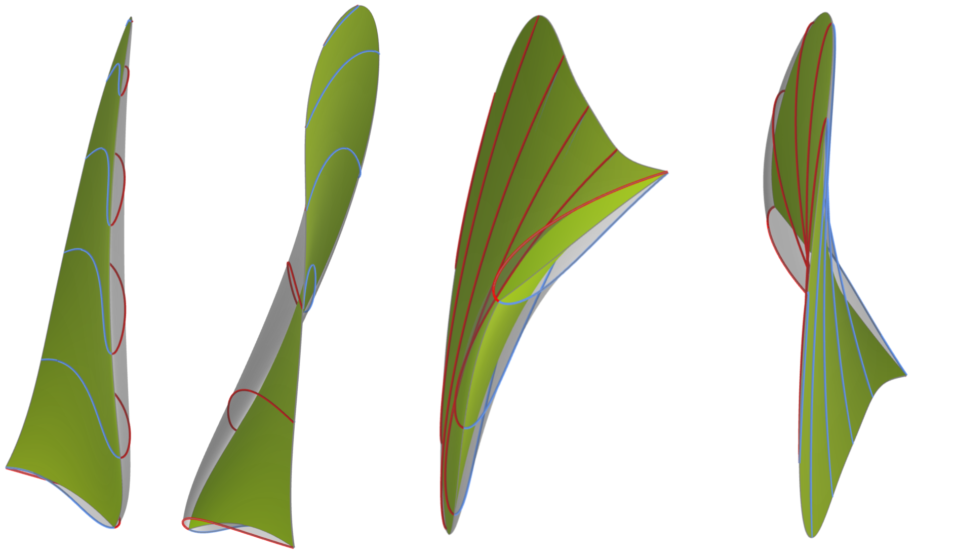
The Center Surface is not the same as the Camber Surface, which incorporates the camber of the profile. This distinction was made to separate the process of defining the propeller's radial distributions from the profile parameters, which enhances the capability to create unconventional designs and allows for easy modifications to the profile definitions.
Workflow GUI
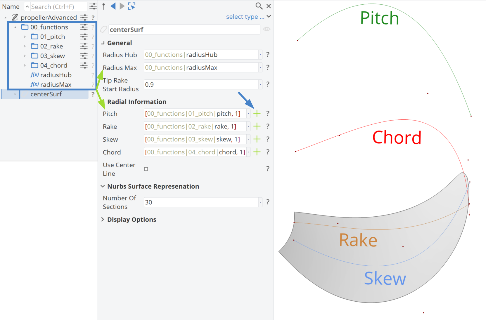
By clicking the green plus button for the Center Surface, a new Center Surface Component is created. Next, you need to click the green plus icon for each distribution individually. The Radius Hub is set to 0.2 of the normal radius and the Radius Max is set to 1. The Tip Rake Start Radius is automatically set to 0.9 r/R, which represents the normalized radius from which the function evaluation is based on the chord length of the rake function. This parameter directly affects the geometry of the blade's tip rake. In simpler terms, it acts as a threshold that determines the extent of the tip rake shaping, ensuring a smooth and precise transition in the blade's tip region.
Finally, if the Use Center Line checkbox is activated, the blade's generatrix can be described using a 3D Centerline, eliminating the need for rake and skew functions.
Radial Distributions
The radial distributions are used to generate the Center Surface, as illustrated in the figure above. These distributions are defined as 3rd-degree B-Spline curves and users can choose the number of control points for each curve. The workflow then automatically assigns the corresponding parameterization, along with several associated parameters.
This serves as a proposed starting point, but you have the flexibility to modify these curves or use your own custom distributions.
Step 2 | Define a Profile Configurator
The next step is to include the information for the blade profile and generate a profile feature definition to be used for the propeller blade.
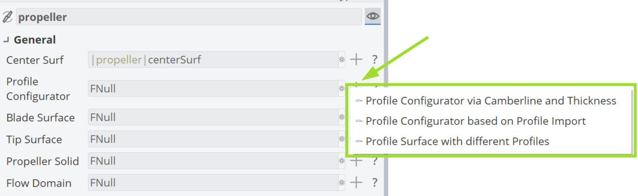
The 2D profile definition can be created in three ways:
- Camberline and thickness curve
- Profile import
- Profile surface with different profiles
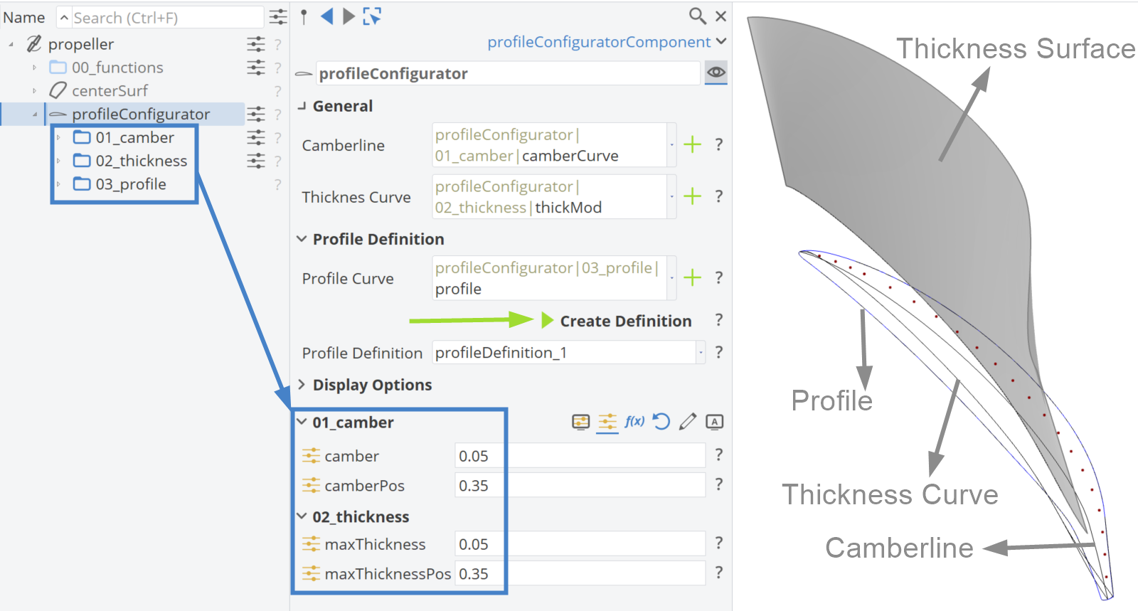
Profile Configurator via Camberline and Thickness
Within CAESES, you can use the embedded tools to create a profile by selecting the Camberline and Thickness Curve from well-established and tested distributions (NACA) or custom parametric curves.
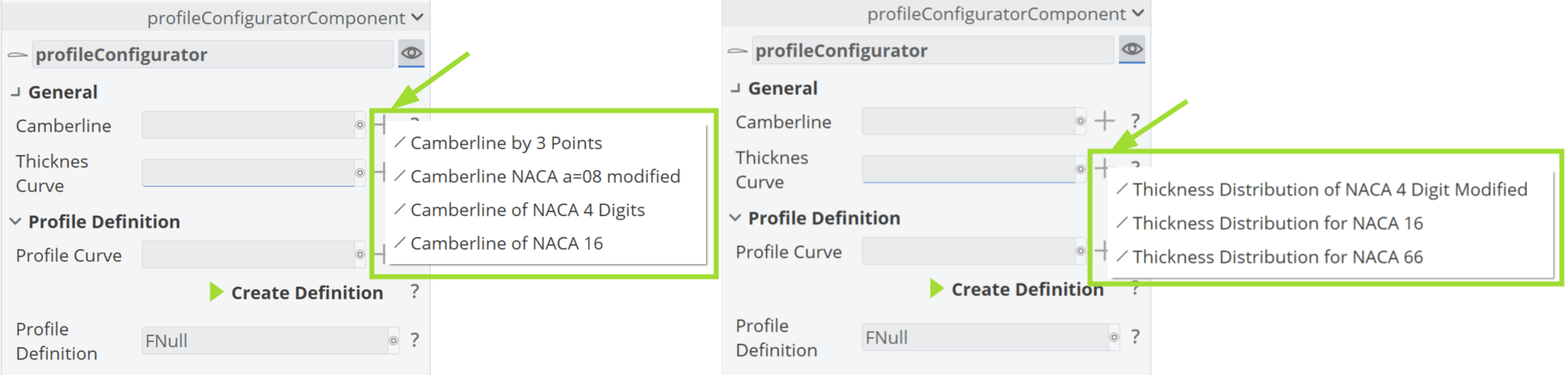
Camberline
- 3 points: Define the camberline using three key control points to shape the curvature.
- NACA a=08 modified: A modified version of the NACA a=08 camberline, offering more flexibility for specific design needs.
- NACA 4 Digits: The standard NACA 4-digit camberline used for basic profile configurations.
- NACA 16: A camberline based on the NACA 16 series, suited for more advanced designs.
Thickness Curve
- NACA 4 Digit Modified: A modified NACA 4-digit thickness curve that allows for adjustments in thickness distribution
- NACA 16: A thickness curve based on the NACA 16 series, providing refined control over the airfoil shape
- NACA 66: A specialized NACA 66 thickness curve, typically used for high-performance, low-drag designs
Profile Configurator based on Profile Import
In addition to the built-in tools in CAESES for creating profiles, users can import their own profiles in ASCII format. Two websites that offer a wide selection of airfoil profiles are:
From these sites, you can download various airfoil shapes available in literature. We have developed a tool that reads the imported file, recognizes the pressure and suction side and extracts the Camberline and Thickness Curve from the data.
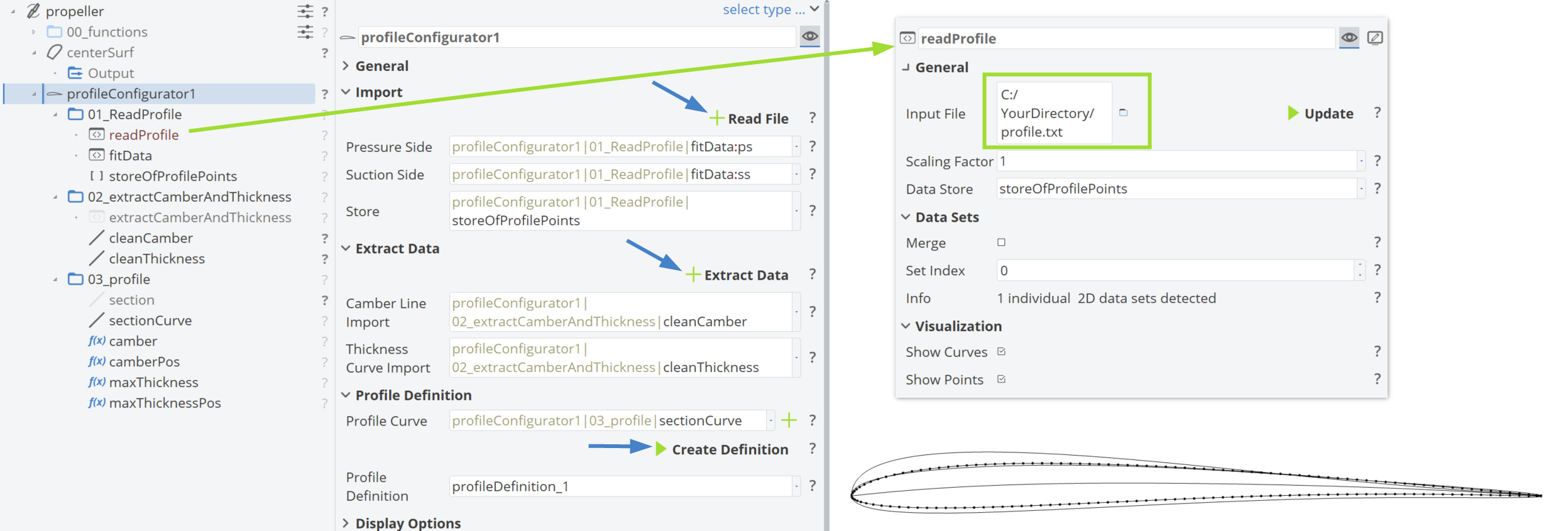
In the workflow, the imported profile is fitted with well behaved NURBS curves and analyzed with respect to camber and thickness distributions. In the end, the profile can be adjusted by camber and thickness.
Follow the tutorial to learn how to import, read and fit point data in the propeller workflow and to make use of an importing propeller profile.
Profile Surface with Different Profiles
In propeller design, different profiles are often used near the hub and near the tip region. This functionality is included in the workflow and should be provided as an FObjectList in CAESES, along with a normalized position range from 0 (hub) to 1 (tip), indicating where each profile is enabled.
Profile Curve
Once the distributions for camber and thickness are defined, clicking the plus button next to Profile Curve generates such a profile curve. From this point, a feature for the profile section definition can be created, which will be used for the generation of the blade surface in the next step. The Thickness Surface shown in the figure below is mapped normal to the Camberline.
Step 3 | Create the Blade Surface
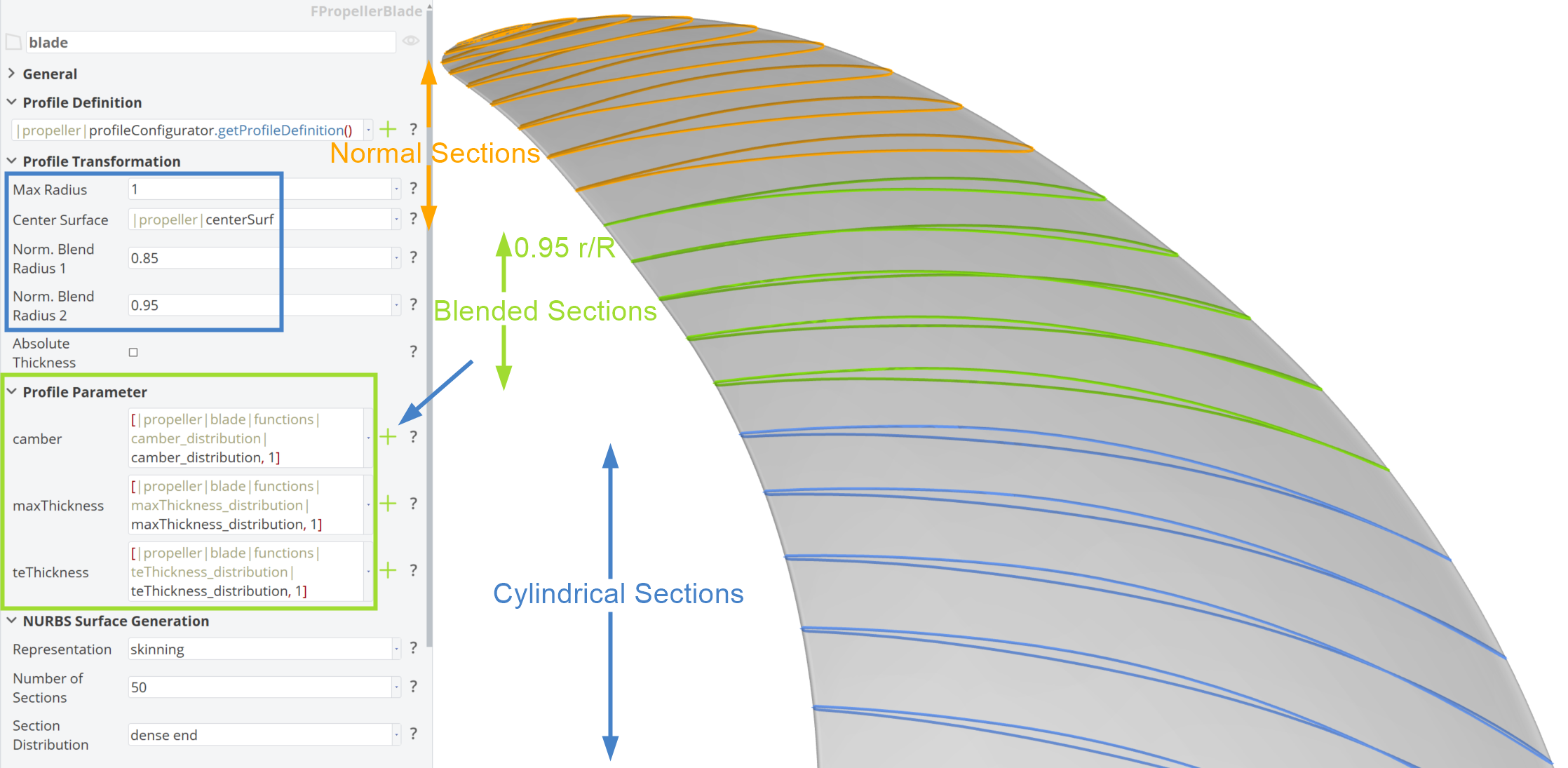
The blade is a FPropellerBlade object, which is based on a Meta Surface with open edges at the tip and hub regions. To define this, the Center Surface (Step 1) and Profile Definition (Step 2) are employed, as depicted in the figure below.
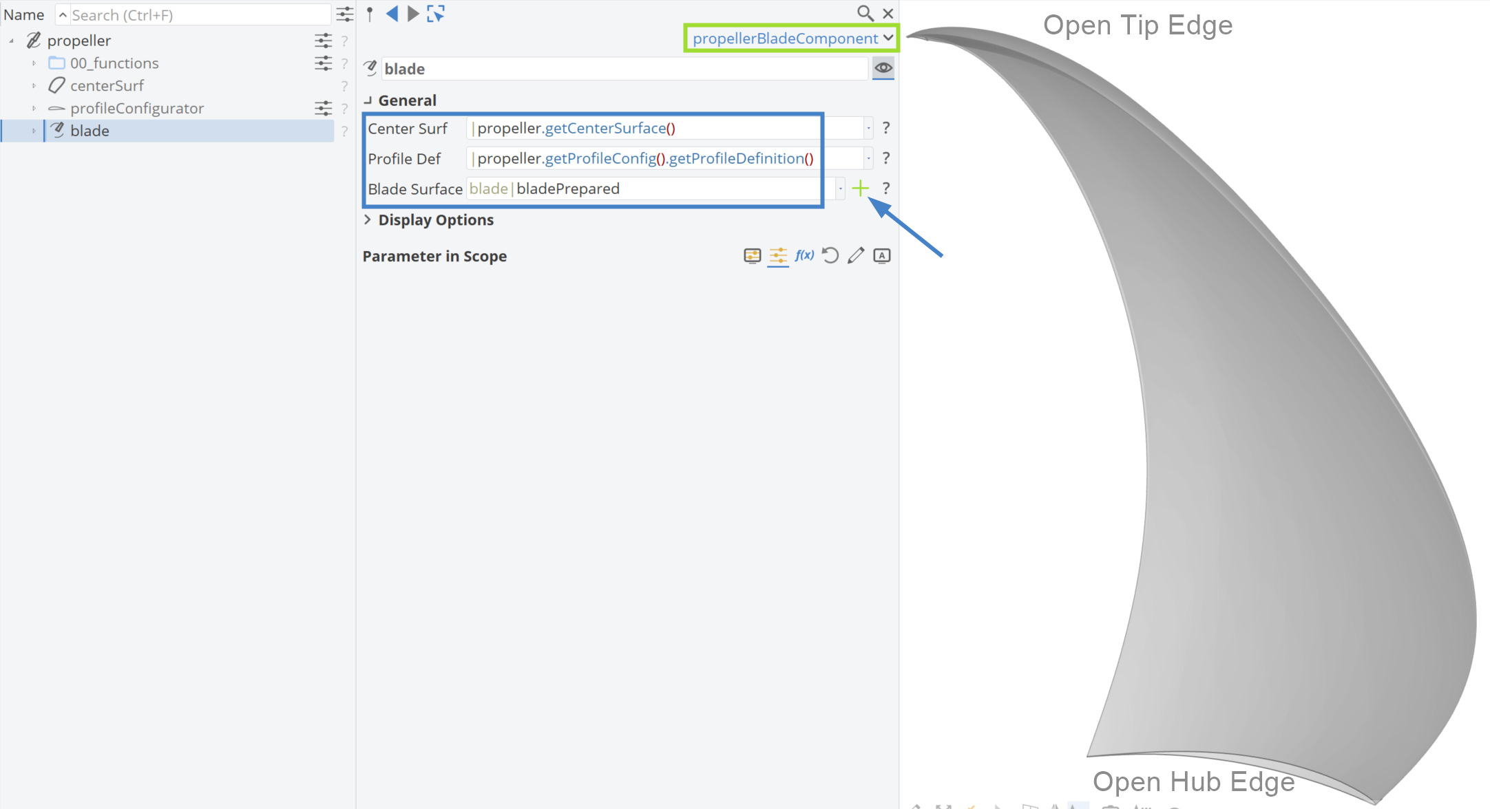
Specifically, when using FPropellerBlade, in addition to the inputs mentioned, two values are required: Norm. Blend Radius 1 and Norm. Blend Radius 2. These values enable the creation of unconventional designs, such as tip rake and highly skewed propellers, without being restricted to conventional cylindrical sections. This avoids the limitations of traditional cylindrical designs, which, while essential, can be considered outdated in modern propeller design.
For example, tip rake propellers cannot be accurately described using only cylindrical definitions. As shown in the figure below, up to Norm. Blend Radius 1 (in this example, 0.85 r/R), the propeller is described with cylindrical sections (shown in blue). From Norm. Blend Radius 2 (0.95 r/R) to the tip, the sections follow the v-direction of the center surface, creating sections normal to the center surface (shown in red). The space between Norm. Blend Radius 1 and Norm. Blend Radius 2 is a blend between these two approaches, represented by the green sections. If you would like to design a typical propeller using only cylindrical sections, you can set both values to 1.
You can also create distributions for Profile Parameters by clicking the green plus button and selecting from the following options:
- Distribution via B-Spline Curve
- Distribution via Interpolation Curve
- Distribution with Tangent Control
Step 4 | Create the Tip Surface
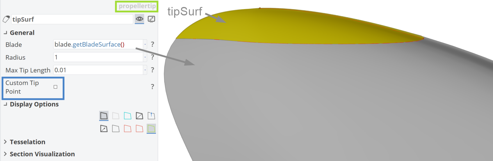
The tip region of the blade, which is always a tricky area in propeller design, is addressed with a dedicated step in the workflow. Using the Blade Surface from the previous step with blade.getBladeSurface(), a tip surface that closes the blade surface can easily be created in CAESES. A custom tip point can be defined and unconventional blade designs can be closed with the tip surface.
Step 5 | Create the Propeller Solid
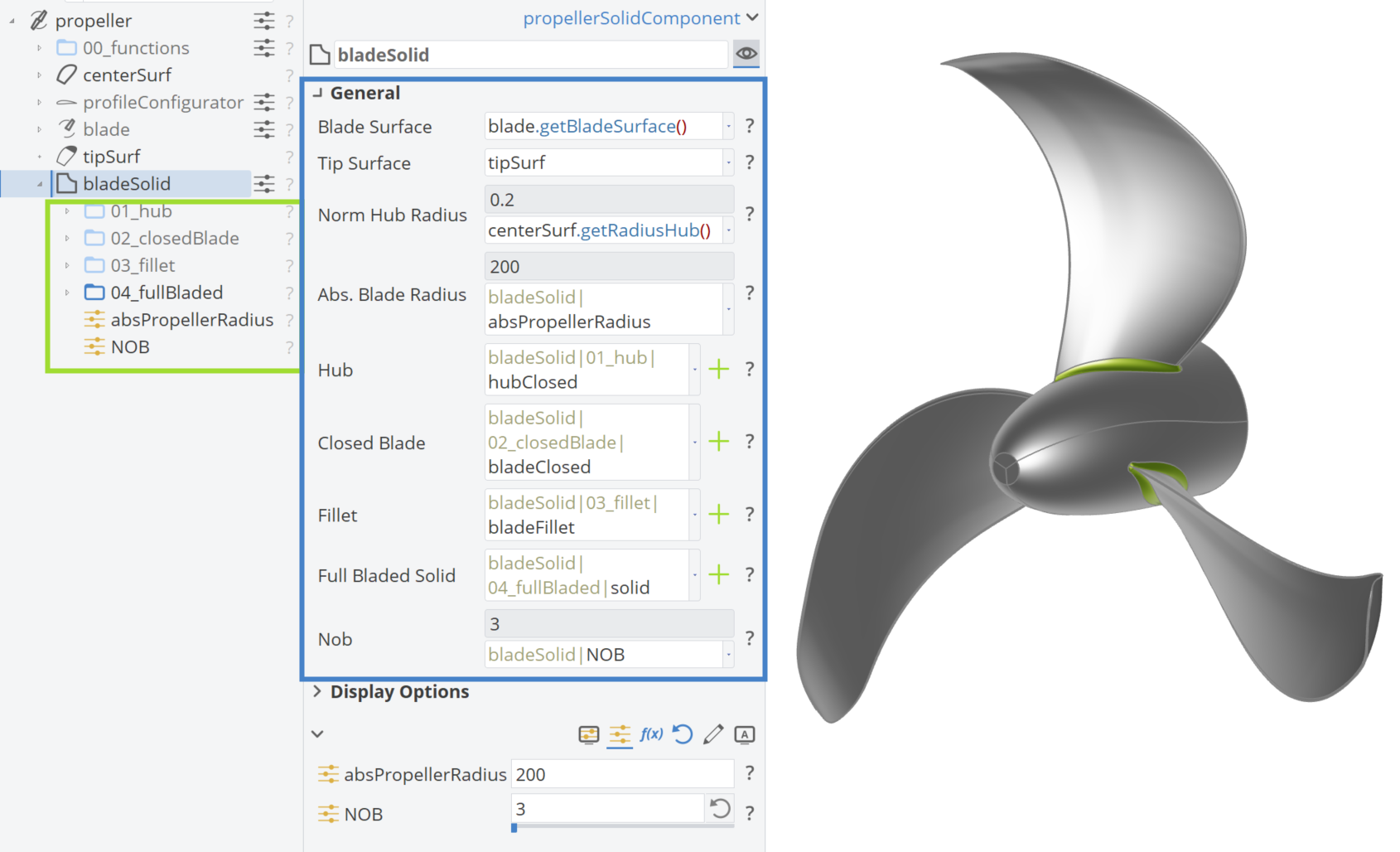
In this step, we will create the entire propeller, including the hub, closed blade (blade surface with closed tip), scaling related to the propeller radius (absPropellerRadius) and the fillet, along with all the blades (the number of blades is defined by the parameter NOB). The creation of the hub, the closing of the blade, how to add a blade fillet and the creation of the full bladed solid are described in the following sections. An overview is shown in the figure below.
Hub
A simplified version of the hub is incorporated into the propeller workflow. The hub is created by defining a hubContour with three control points and using an FRevSurface to generate the hubSurf*. Then, a BRep is created, named hubClosed, which is forming a watertight closed solid with the BRep Operation close planar holes.
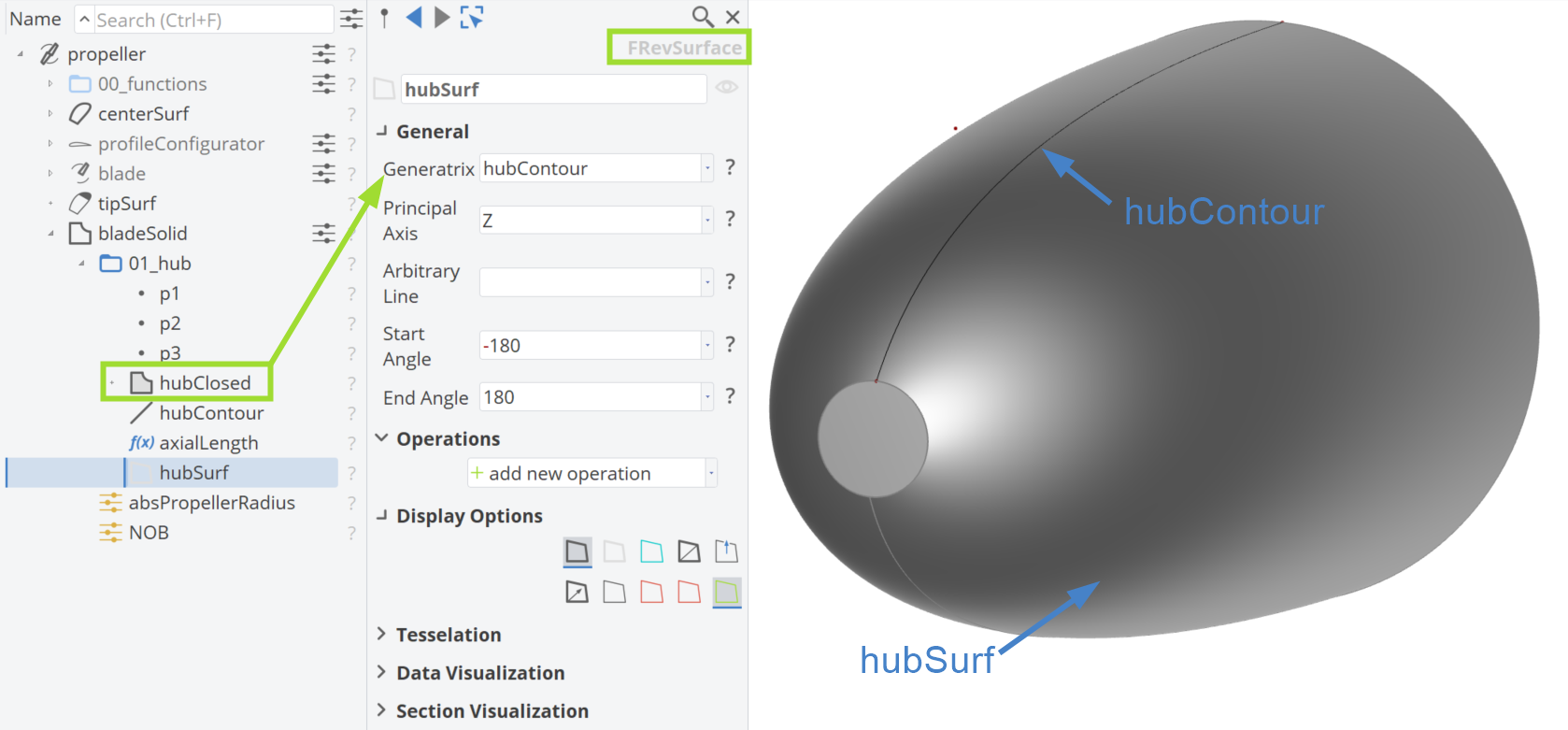
This simplified hub can always be replaced with custom or imported geometry, which is a common practice in propeller design.
Closed Blade
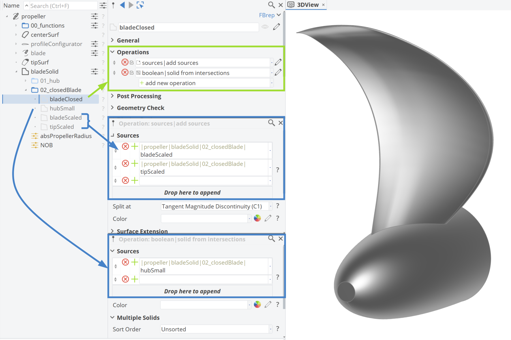
The main part of the Blade Surface, along with the Tip Surface, is scaled and provided as input for the BRep (referred to as bladeScaled and tipScaled). Next, the open edge at the hub is closed using a boolean operation with the Solid from Intersections, incorporating the hub BRep as well.
Fillet
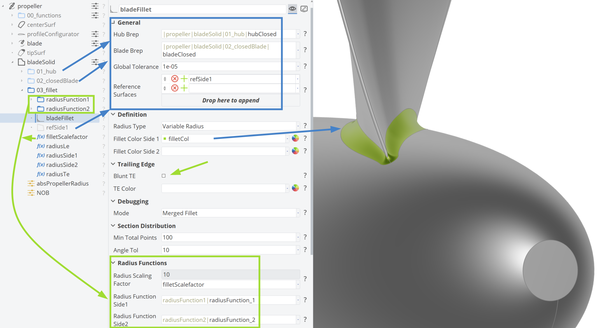
A smooth connection between the blade and the hub is achieved in propeller design through a fillet region. A Variable Fillet Radius is utilized, which is more effective than a constant fillet radius, as it focuses on the areas near the blade root where it is most needed. Read more about propeller blade fillets and the transition surface between hub and blade in the structural design section.
The figure below illustrates the feature for creating the variable radius fillet. Several inputs need to be filled out, but this workflow in CAESES prepares everything for you, allowing you to easily manipulate radius functions or the filletScaleFactor to adjust the fillet radius.
Full Bladed Solid
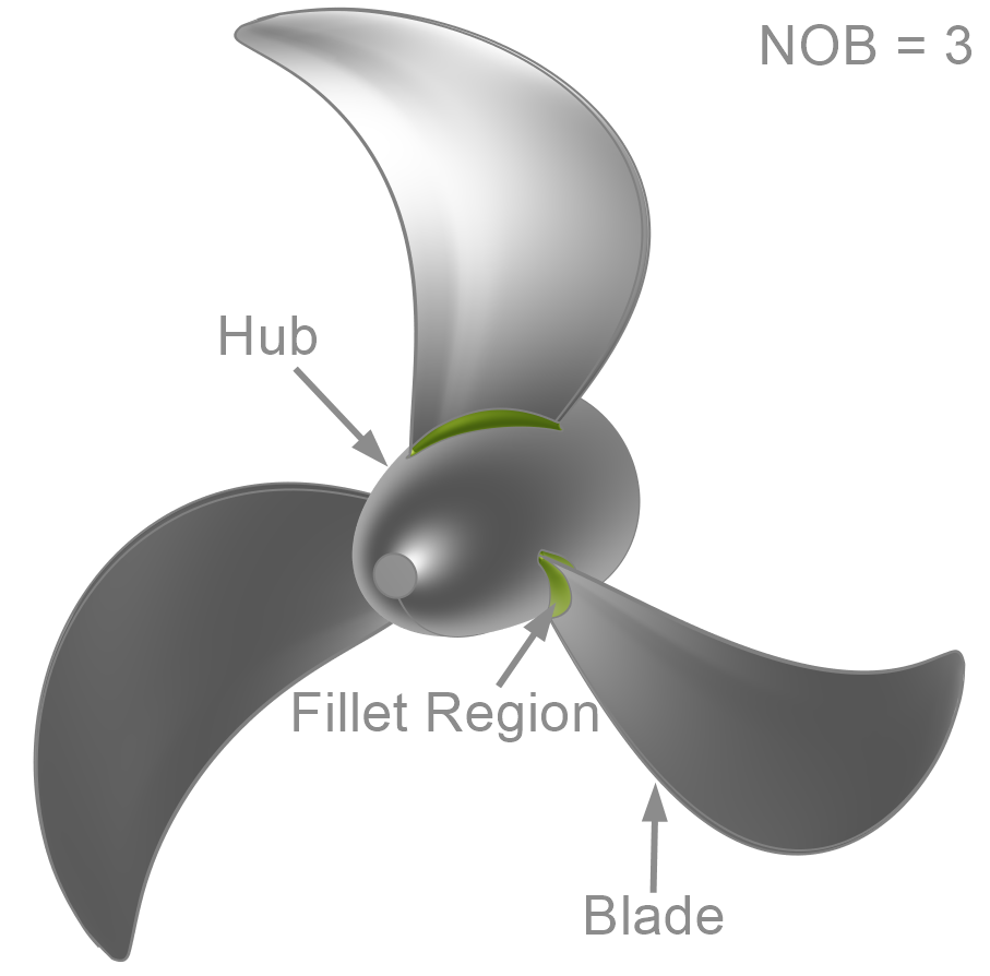
The number of blades (NOB) can be adjusted using the Design Variable NOB. This means that the blade, along with the fillet connected to the hub, is rotated around the axis of rotation.
Step 6 | Create a Flow Domain
Since CAESES handles not only the parametric modeling but also CFD connection, the final step covers the creation of a Flow Domain.
There are two options for defining the domain, controlled by the checkbox labeled Periodic Cut:
- Cylindrical Domain: Encompasses all propeller blades.
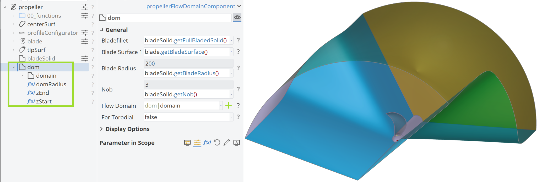
- Axial Domain: A more efficient method that includes only a single blade, significantly reducing computational time. The CFD solution assumes symmetry, meaning the problem only needs to be solved once, rather than NOB (Number of Blades) times, as it is the case with the cylindrical domain.
The axial domain follows the blade's pitch angle, resulting in the twist illustrated below. This ensures an accurate domain for your CFD calculations. Additionally, there's an option to Extend the Shaft in Z-axis.
Customize the entire propeller workflow to your needs. You can replace the generated curves and parameters with your custom ones. Simply set your own curve type for the distribution functions and choose your own free design variables. Additionally, if you have an older setup that doesn't use this propeller workflow, all of your previous configurations will remain intact.
Detailed Tutorials
Check out the detailed tutorials for the Advanced Propeller Workflow and the Toroidal Propeller Workflow.
Sample Models
Take a look at the propeller sample models that are available with the Propeller Add-On and browse through ideas of how to set up your parametric model or use them as a starting point to kick-start your model setup.
There are sample models available for a: