Maritime StarCCM+ Connection
For Ship Hull Evaluation
To accelerate the process of connecting the modelled ship hull in CAESES with StarCCM+ in order to analyze its performance in various conditions and seamlessly integrate it into a shape optimization, the newly released maritime release add-on offers a default StarCCM+ connector. This default setup is especially helpful, if linking different software with each other is new to you but can also help in accelerating the setup of complex connectors since the basic framework stays unchanged. Needless to say, this default connection is just a basic example on how to connect CAESES to StarCCM®+ and therefore does not provide a correct simulation setup for a specific case. Hence, it is up to the engineer to change input variables, files or output variables to tailor the connection that is suited to the specific simulation case.
This connector to StarCCM+ is NOT intended as a best-practice example but as a guide how StarCCM+ can be connected with CAESES in a well-structured manner. The setup of the StarCCM+ connection is based on a ship model, which was created by using the ship modelling workflow in CAESES. This default connector only works, if the ship was modelled with the ship modelling workflow.
The setup of the StarCCM+ connection is based on a completed model created using the ship modeling workflow:
Get Started With Ship Hull ModelThis connection is a basic example on how to connect a hull to a hull resistance prediction simulation. The hull resistance prediction setup in StarCCM+ is based on the tutorial "Marine Resistance Prediction: KCS Hull with a Rudder". The tutorial can be found inside the StarCCM+ User Guide, which can be accessed by navigating to Tutorials > Motion > Marine Resistance Prediction: KCS Hull with a Rudder.
Load the Connector
After the ship has been modelled by using the ship modelling workflow in CAESES, navigate to Model > Maritime tab > Connections category > STAR-CCM+. A new object is created inside the object tree called cfd_loadStarCCMConnector.
- First, reference the ship inside the object editor in the input field Ship Component in the category Ship.
- Afterwards, scroll down to the category Executable and enter the path to your local StarCCM+ executable. The path input must be of the type FString.

- Subsequently, navigate to the category Operating Condition at the bottom of the object editor to choose between two different operating conditions. By default, the operating condition index is set to
0, meaning that the ship is operating at its design speed. If the ship should operate in slow steaming conditions, change the index to1. - In addition, it is possible to choose between two different Floating Conditions. The first floating condition is salt water, which can be selected by leaving the default floating condition index set at
0. By switching the index to1, a floating condition in fresh water is selected.
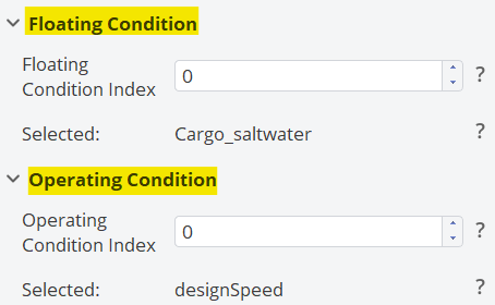
The other input variables are set as default values, which can be changed inside the Connect workspace later on.
- Let's run the feature by either clicking the green execute button in the top blue ribbon or by right-clicking on the feature inside the object tree and selecting "Run" from the drop-down menu.
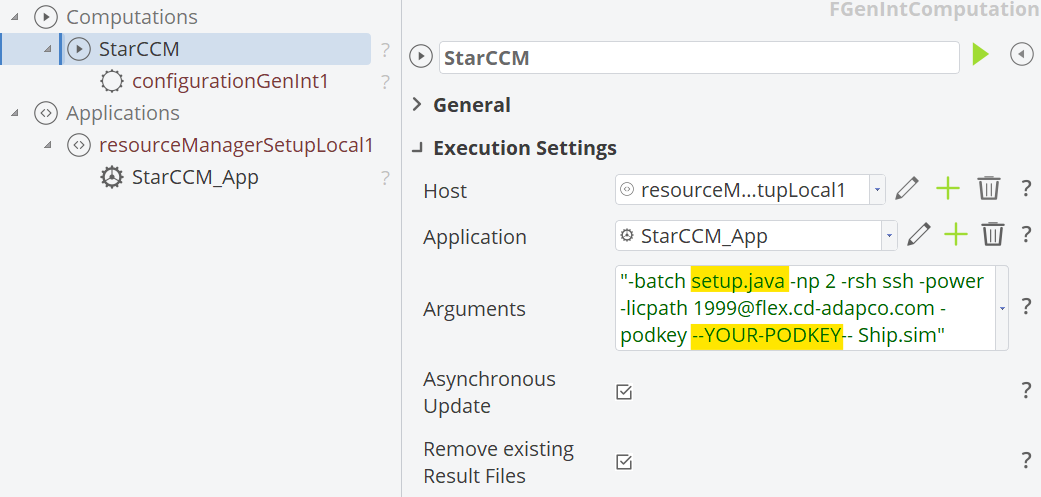
When navigating towards the Connect workspace, a connector should now be visible called "StarCCM" after expanding the Computations node in the object tree. In addition, a local application should have been created named "StarCCM_App" under the Applications node, containing the path to the local StarCCM+ executable.

Connector Configuration
Since the default connection is created and potentially ready to be executed, let's start to understand the default connector setup by diving deeper into its individual components, starting with the execution settings.
Execution Settings
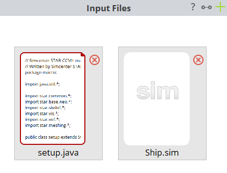
Inside the execution settings, the host is defined, the local application is referenced and the arguments regarding the simulation are formulated. Here, it is important, that the correct name of the java-macro file is referenced from the input files (in case you want to exchange the macro file, keep in mind to change the name in the arguments), here being setup.java, and that you insert your license key where it says --YOUR-PODKEY-- to start and run StarCCM+ in batch mode.
Input Geometry
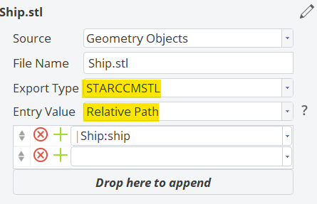
- To open the input geometry dialogue, click on the
Ship.stlfile inside the connector.
The input geometry is automatically referenced by the default connector and the hull is exported as a StarCCM STL file. In this example, the entry value is set to Relative Path, which sets all referencing paths relative towards the current CAESES project file location. Hence, if the STL export file is referenced inside the java macro file, only the file name (in this case Ship.stl) needs to be set instead of the absolute path.
Input Files
As already mentioned in the introduction, the default simulation setup is based on the StarCCM+ tutorial "Marine Resistance Prediction: KCS Hull with a Rudder", which can be accessed through the online accessible User Guide from StarCCM+. If you are interested in the mesh creation, physical setup and other pre-processing specifications, we suggest to take a closer look into the tutorial in the StarCCM+ User Guide. Also, if you would like to check or modify the setup of the StarCCM+ simulation file, you can download the Ship.sim file here:
Java Macro File
To access the java macro file, open the tab named setup.java or double-click on the setup.java file inside the connector. Following steps are conducted during pre-processing by the default java macro file:
-
Replace the ship model.
-
Scale the model according to the scaling factor (). The operating- (i.e. speed), floating- (i.e. draft) and other boundary conditions are automatically set with respect to the defined scaling factor and the referenced ship.
-
Create the virtual towing tank by subtracting the scaled geometry from the specified block geometry in StarCCM+.
-
Set the mesh parameters. In this case only for demonstration the mesh base size is set as an input variable with a value similar to the tutorial in StarCCM®. Feel free to adjust, add or delete any input variables to your preference.
-
Create a volume mesh from the domain by applying the automated mesh operation.
-
Set the scaled ship model's draft, depending on which floating condition was selected inside the cfd_loadStarCCMConnector feature.
-
The velocity of the ship is determined by the selected operating condition inside the cfd_loadStarCCM feature (operating condition index =
0→ design speed,1→ slow steaming). By applying Froude similarity, the conditions inside the virtual towing tank (velocity of water and wind) are determined:.
infoIn this example, there is no wind included, thus the default values of the water and wind velocity are identical.
-
The density of the water is set according input parameter Density Water.
-
The mass of the scaled ship model is estimated by firstly determining the displacement of the model's hull and subsequently deriving the mass from it:
-
The moment of inertia around the X-Axis and Z-Axis are determined by applying two dimensionless design parameters:
( being the inertia radius and being the beam of the ship),
( being the inertia radius around the Z-Axis and being the length between perpendiculars of the ship).
The default values of these dimensionless parameters are set to:
It is now possible to determine the inertia radius from the scaled model around the X- and Z-Axis through the dimensionless parameters:
With the inertia radius determined, the scaled moment of inertia can be obtained by:
-
The scaled model's center of mass is determined by linearly scaling the ship's vertical center of buoyancy and lateral center of buoyancy:
-
To edit the solver parameters before the simulation, the implicit solver time step is set as an input variable inside the java macro file to exemplify, how to implement variable solver parameters.
-
The default connector offers two different options regarding the stopping criterion.
- The first option is to set the number of maximum iterations after which the simulation will be terminated. To choose this stopping criterion, enter
trueor1next to the entry field Stopping Criterion: Maximum Iterations. When using this stopping criterion method, it is necessary to specify the number of iterations, the number of inner iterations and the physical time step. - The second option offers an asymptotic stopping criterion, which will terminate the simulation once a defined asymptotic limit is reached. The asymptotic limit sets the minimum interval in which the change of the object function is tolerated averaged over 10 samples. To choose the asymptotic stopping criterion, simply enter
trueor1next to the entry field Stopping Criterion: Asymptotic and specify the asymptotic limit.
noteOnly one stopping criterion can be chosen at a time. Hence, if setting one criterion to
true, the other criterion must be set tofalse. - The first option is to set the number of maximum iterations after which the simulation will be terminated. To choose this stopping criterion, enter
If you want to change the input variables or the java macro file itself, feel free to do so. This default connection is just showcasing how to establish a running connection between CAESES and StarCCM+.
Result Files
To import plots, e.g., residual plots and plots from the objective function, or other simulation data such as the visualization of the wave pattern, which can be of interest when analyzing a ship's performance, simply export them from the .sim file as "Hardcopy" and import them into the Result Files window. The export commands are recorded inside StarCCM+ and thus are written into the java macro file. Since the relative path option is selected, all absolute paths from each file can be changed towards the file's name. If you would like to add or delete result files, simply modify the entries inside the result files window and change the commands in the java macro file between line 198-227.
In this example following plots and figures are imported into CAESES:
Convergence data
- Residual plot
Resistance data
- Total drag plot (objective function)
- Plot from the individual drag components (pressure drag and shear drag)
Motion data
- Plot of the sinkage and trim of the ship (Motion Plot)
Forces and moments
- Force in the Z-direction of the ship
- Moment around the Y-Axis of the ship
Visualization
- Wave pattern
- Free water surface
Result Values
To import the result values from the simulation in CAESES and later on integrate them in optimization loops, the values from the total drag and individual drag components are imported as *.csv files in the Result Values window. This was done similarly to the result files by recording the export commands inside the *.sim file (export as "Export" will lead to an export as *.csv file) and subsequently importing the *.csv files into the Result Values window. Again, to change the files, simply modify them inside the connector and change the commands inside the java macro file between line 230-233.
- To extract a result value from the
*.csv-file, double-click on the file in the connector, which opens the file in a new tab and subsequently click on the green +-icon on the right in the Values category. This will create a result value entry inside the table at the bottom. Now, it is possible to rename the parameter. To extract a certain value from the*.csv-file, specify the row and column which will lead to the correct extracted value or toggle the option Average, which will extract an average over a specified amount of result values. At the end, you can create a parameter from the extracted value, by navigating to the right column of the table and click on the blue parameter icon (). When navigating back to the CAD workspace, a newly created parameter can be seen now inside the object tree with the extracted value from the*.csv-file. This parameter can now be integrated into an optimization loop inside the Optimize workspace.

CAESES Project File
If you want to take a look at the finalized software connection setup and the model you can find the resulting CAESES project file ship-starccm-connection.cdb here:
Disclaimer
Our services are not approved or endorsed by Siemens Digital Industries Software, the producer of the StarCCM+ software and owner of the StarCCM+ trademark. Nor do we take any responsibility for results obtained by using StarCCM+ or any of its components.