OpenFOAM Connection
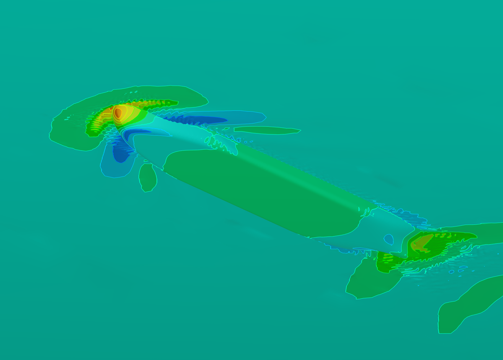
For the evaluation of the hull shape generated using the ship modelling workflow various tools are available. Among the CFD-based tools a SoftwareConnector to the OpenFOAM®-based solver interFoam with the workflow of pre-processing, solving and generation of post-processed data is included.
This connector to interFoam is NOT intended as a best-practice example but rather as a guide how an openFOAM®-solver can be linked to CAESES in a well-structured manner.
Workflow
The setup of the OpenFOAM® connection is based on a Component-based Ship from the Ship Modeling Workflow:
Get Started With Ship Hull ModelModel Preparation
For the CFD simulations a tessellated geometry of the ship is required, if the simulations are to be run at model scale this has to be scaled accordingly.
Add Scope to Project Structure
- To prepare the geometry start by creating a new scope named
99_CFDin Model > CAD.
Define Path to OpenFOAM Installation
- Start by defining the path to the
bashrcfile of the OpenFOAM installation. This is required as the shells called by the CAESES SoftwareConnectors do not source the.bashrcor.cshrcfiles. - Create a String Parameter (Model > CAD > Parameters > More) in the scope 99_CFD, name it
OFBashrcPathand set the path to your OpenFOAM® installation.
The actual path depends on the individual OpenFOAM® installation, but a typical path for a global installation could for example be /opt/OpenFOAM/OpenFOAM-v2112/etc/bashrc.
Scaling
- To prepare the scaling of the geometry and flow settings for the simulation create a Parameter in the scope
99_CFDand name it "lambda". - Set the value of the parameter lambda to
20(for a scale of1/20) This scaling is later applied to the geometry and settings in the CFD workflow executed via the Connector.
Software Connector
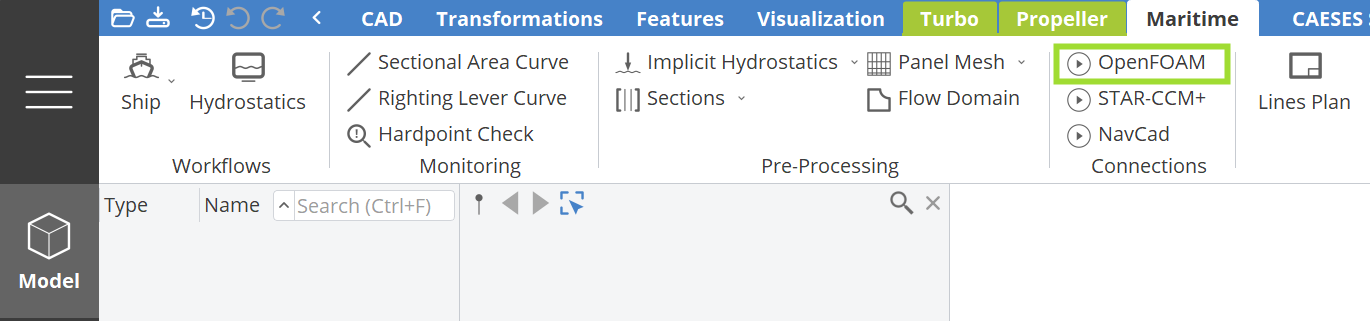
- By selecting the OpenFOAM button in the Model > Maritime tab the dialogue to load the OpenFOAM® Connector is invoked.
This is to be filled with the objects created in the |CFD scope as well with the Ship Model. The Number of Partitions settings is specific to the machine used to solve the CFD case. The turbulence parameters are default settings, , and as required by OpenFOAM® are calculated as described below.
It is recommended to use a parameter for "Lambda", as this value is used in multiple locations within the Connector and can then be referenced more easily.
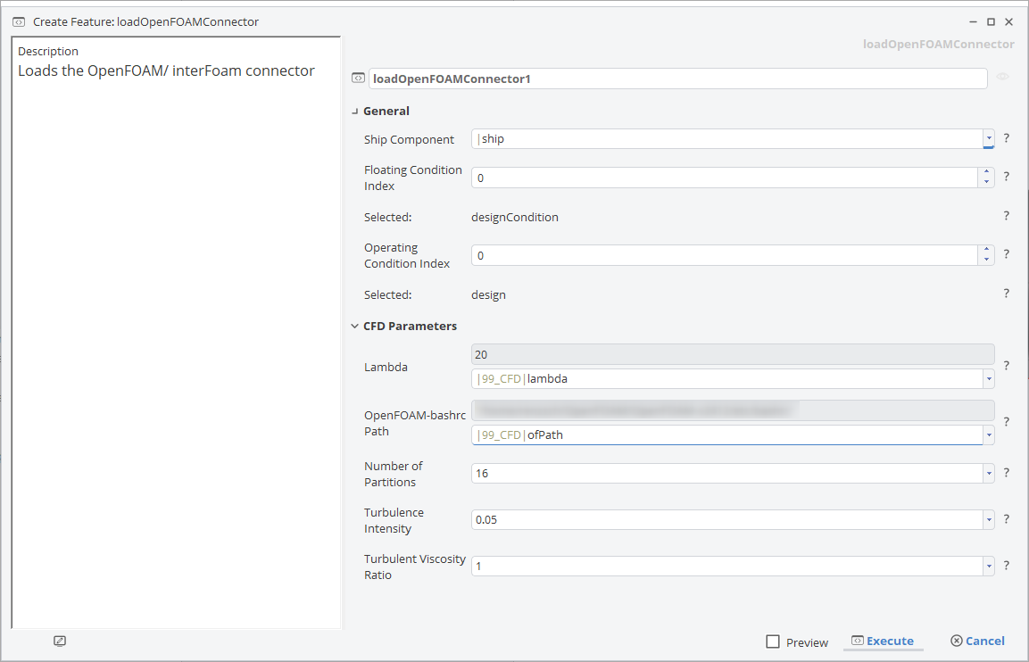
- To create the Software Connector hit the Execute button.
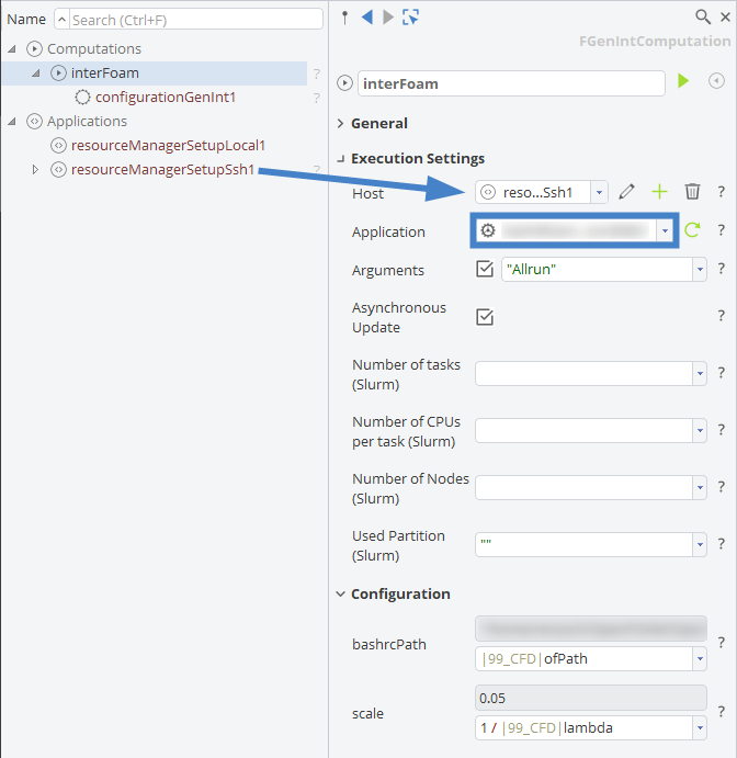
Following this, the Connector interFoam appears in Connect > Connection, in the tree under Computations, with the settings for Configuration, hull.stl and openFoamInput as provided in the dialogue.
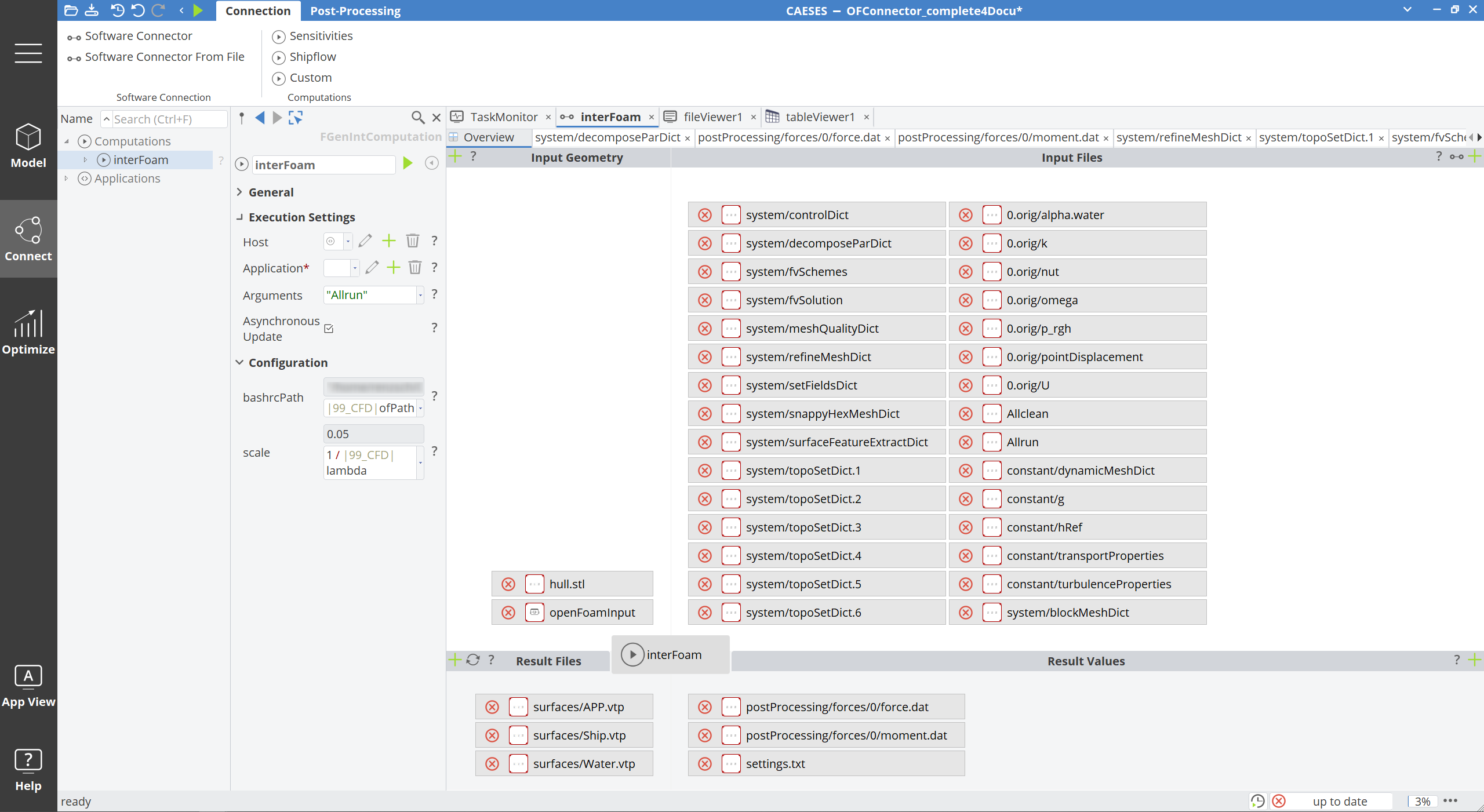
To finalize the setup, the computational environment has to be configured:
Results
For ease of post-processing two sets of result files are provided:
- time series of forces and moments under Connect > Result Values and
- VTK-files of the hull, free surface and wake cut under Connect > Result Files. These allow further post-processing of integral values and visualizations in CAESES. An example is given in the CFD Post-Processing tutorial.
Technical Description of Setup
The interFoam setup has been tested to work with OpenFOAM-v2112 but should work with any newer version of the OpenCFD branch, too. It is a parametrized version of the setup for the DTCHullMoving tutorial provided by OpenCFD.
In the setup the absolute values (e.g. ship speed, hydrostatics and blockMesh data) have been replaced by variables. These are read from the file settings.txt. This file is created by the Feature cfd_interFoam which forms part of the SoftwareConnector. In the following those settings which have been parametrized or are calculated depending on the actual case are described.
Domain Size and Settings
Based on the domain as given in the above-mentioned example the size, as well as resolution of the domain has been parametrized based on the length of the ship. In particular, this includes the resolution of the free surface region. Domain dimensions in relation to ship length are:
- 1.5 times in front,
- 4 times in aft,
- 3 times to the side,
- 2.5 times below, and
- 0.5 times above.
The region inside 0.01 times length below and above the free surface is particularly refined.
Turbulence Settings
By default OpenFOAM® requires the provision of turbulence variables (e.g. k, , ). As these are speed-dependent, a conversion from the more intuitive variables TI and has been included:
Default values for TI and are 0.05 and 1, respectively.
Motion Solver Settings
To evaluate dynamic trim and sinkage the sixDoFRigidBodyMotion motion solver provided by OpenFOAM® is used. This solver provides a selection of solution algorithms to compute the motion per time step from the computed forces but all include an extrapolation step requiring stabilizing measures to avoid the risk of divergence. A possible way to stabilize the motion computation is to provide damping ratios for translational and rotational motions. While the documentation of OpenFOAM® does not provide any guidelines on how to compute these damping ratios the implementation hints at a viscous damping approach (damping forces proportional to motion velocity). Lacking any further guidance the damping coefficients are calculated for supercritical damping by the feature.
Disclaimer
Our services are not approved or endorsed by ESI Group or ESI-OpenCFD®, the producer of the OpenFOAM® software and owner of the OpenFOAM® trademark. Nor do we take any responsibility for results obtained by using OpenFOAM® or any of its components.
CAESES Project File
If you want to take a look at the finalized software connection setup and the model you can find the resulting CAESES project file ship-open-foam-connection.cdb here: