Fine Marine Pre-Processing
Introduction

This tutorial covers the pre-processing steps for FINEMARINE CFD simulations using a Component-Based Ship obtained from the Ship Modeling Workflow in CAESES. It will guide you through the necessary steps to set up boundary conditions (coloring) within CAESES, enabling the use of HEXPRESS for mesh generation. The export format will be a colored STL.
Use this project file as a starting point which contains a ship object from CAESES version 5.3:
Get Started With Ship Hull ModelThe ship object is constantly updated and new functionality is added with every update of CAESES. However, the steps shown in this tutorial specifically fit to the provided ship object version above. The general approach can be applied to any ship hull.
Requirements
We will use CAESES to provide a complete domain of the ship hull as a triangulated geometry, with individual patches colored according to specific HEXPRESS requirements. The precise naming and selection of refinement regions are the user's responsibility, as a CFD expert would know how to set these parameters for specific simulations. This tutorial presents an approach that highlights the most critical aspects of the process, demonstrating one way to do it while equipping users with the tools and insights to further develop their expertise and approach similar tasks on their own. There are a few important considerations to keep in mind:
-
Avoid sharp corners: Cut a small triangular patch and color it to match a neighboring patch along the edge near the sharp corner. This allows the mesh to "flow" smoothly across patch boundaries, preventing undesirable mesh distortion.
-
Preserve critical edges: Since HEXPRESS allows the mesh to flow across patch boundaries, it is crucial to preserve edges where this behavior is not desired. In these cases, using different colors is necessary. For example, when defining the port and starboard faces of the skeg, distinct coloring ensures that the mesh remains appropriately constrained and the sharp trailing edge of the skeg is maintained.
This approach ensures an optimal and controlled mesh generation process, meeting the needs of both fluid dynamics analysis and geometric fidelity. Let us get started with a Component-Based Ship. For completeness, we will also add a skeg and a bulb. We will assemble a BRep based on the individual components. This way, we can adjust the coloring step by step and handle both symmetric and asymmetric coloring.
Fore Ship and Bulb (Handling of Sharp Edges)
Let us assume that, for a good trade-off between speed and accuracy in the CFD, we want to give the bulb region of the hull a separate color. To adjust the color of the bulb individually, navigate to |ship|bulb|03_brep|01_bulb|bublCompl and create a new color within the add sources operation. Name it "bc_bulbPort". When creating a new BRep based on |ship|bulb|03_brep|completeWithBulb, the color assigned in the previous step will propagate through all intermediate steps.
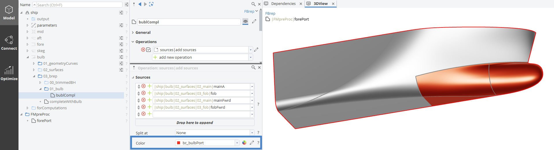
"bc" is just meant to be an identifier for "boundary condition." When sorting by name, this will ensure that all custom colors show up as one block in the colors menu.
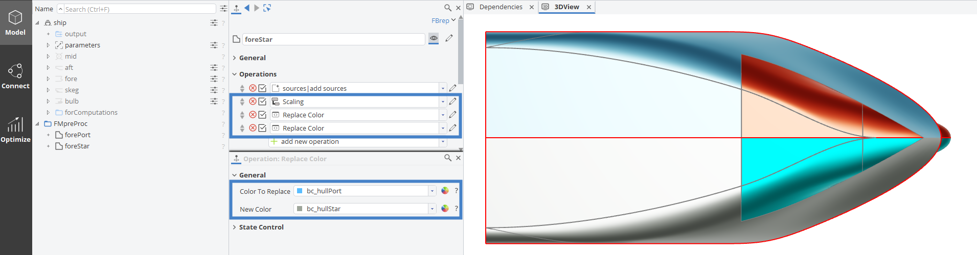
After creating the BRep, we can assign a second color to it, namely "bc_hullPort". This will not overwrite the already addressed patches but only affect the remaining ones.
This part of the hull will be used only for the port side. For the starboard side a similar BRep is needed but with different coloring. The reason we cannot use the same boundary condition on both sides is the sharp entry of the hull at the stem. In order to preserve this edge, a different color needs to be assigned on both sides.
Create a second BRep, name it "foreStar" and assign the first one as a source. A Scaling operation with a Y-Factor of -1 mirrors the hull across the center plane. For the coloring, we can simply use two additional Replace Color operations and create the needed colors in the process.
Mid Ship
The mid ship region is straightforward. Two more BReps are created, one with an additional scaling operation for the mirroring. After assigning the respective colors for the port and starboard side of the hull, the result should look as shown in the following screenshot.
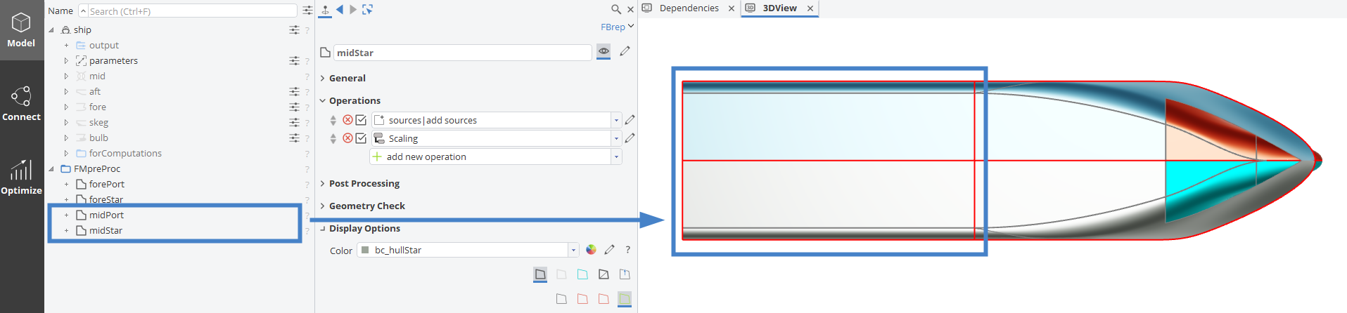
The RGB values of the colors do not serve a specific purpose, other than allowing the user to visually understand the different boundary regions. Only the name (or a custom export name, if specified) is what is used in the downstream process. Make sure to check out the documentation on coloring and boundary conditions to get a better understanding of how and when to use different coloring techniques.
Aft Ship and Skeg (Handling of Sharp Corners)
We will proceed as with the previous segments and color the skeg region individually to allow for a custom mesh refinement in the region of propeller-inflow. In doing so, we notice a sharp corner where the skeg and hull meet near the aft perpendicular:
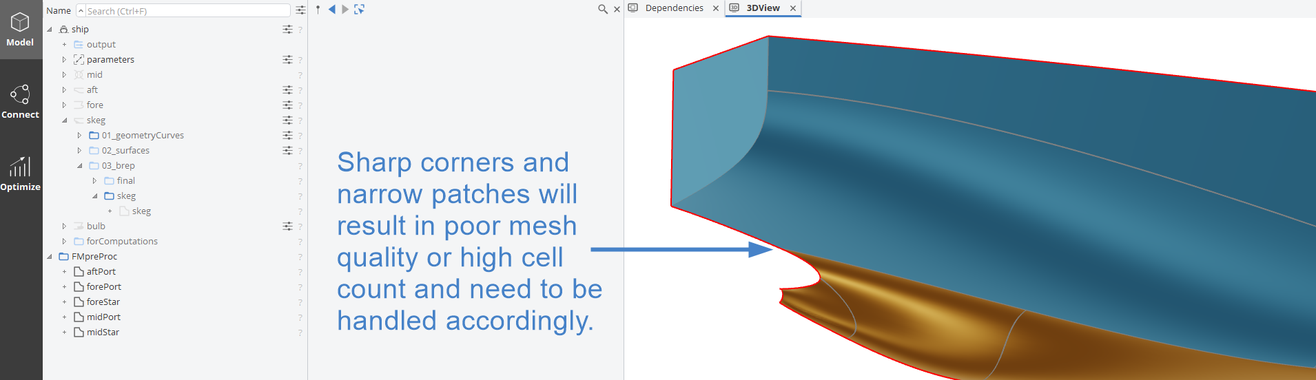
In cases like this, the idea is to make the narrow or sharp region part of an adjacent boundary patch, allowing the surface mesh in HEXPRESS to flow across it. With the complete model available in the scenario outlined in this tutorial, we will do so by identifying the skeg surface and splitting it in a BRep operation. Afterwards, we will assign the same (bc_hullPort) color to the triangular region using a reference point, which we position reliably.
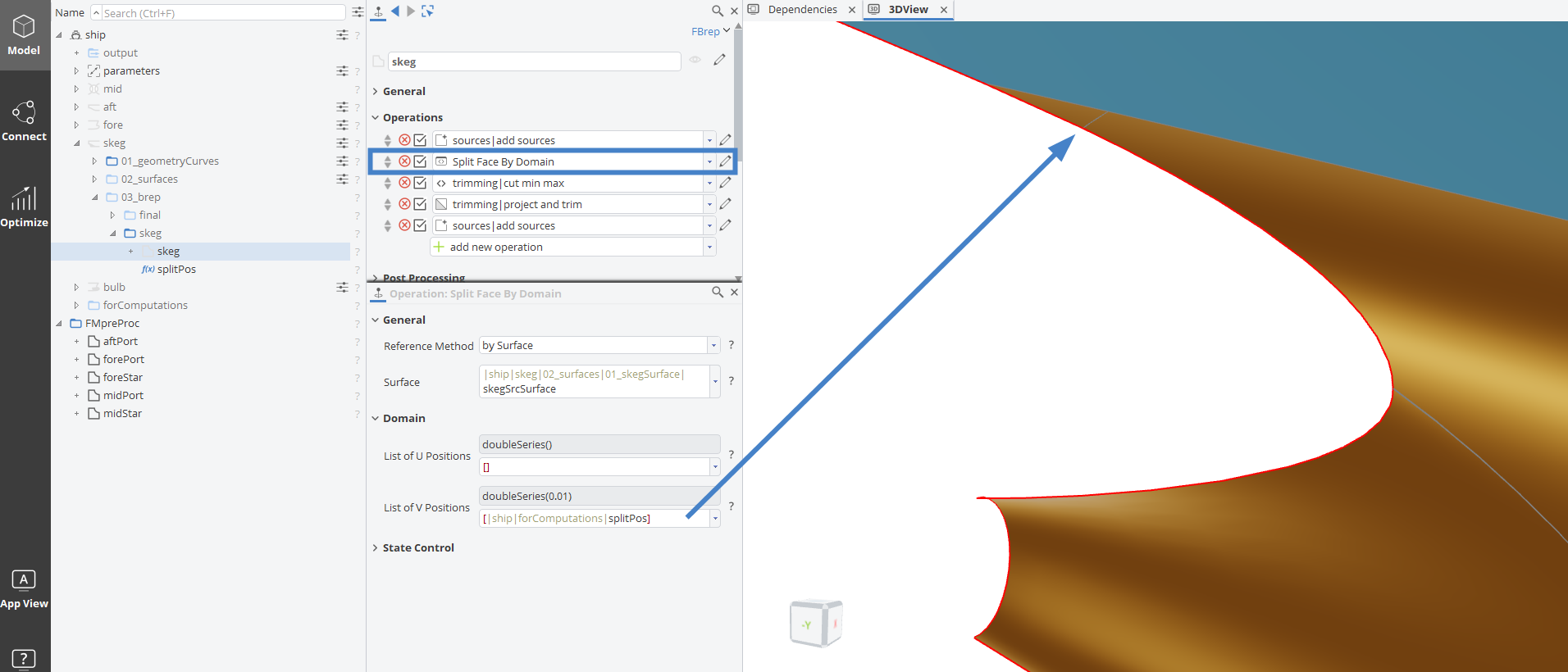
After determining a reasonable value (we will use the 0.01 shown in the screenshot above), we will create a parameter named "splitPos" and position a point centered on the small triangular patch. A Surface Based Point > Position on Surface will work nicely if positioned on the flat bottom surface at:
u = 1 and
v = splitPos * 0.5 .
This will position the point on the very edge of the patch with a Y-coordinate always > 0. If we add a Scaling of 0.5 in y-direction, the point will reliably reference the patch and can be used for coloring purposes. The coloring is done via a Color Patch by Point BRep operation.
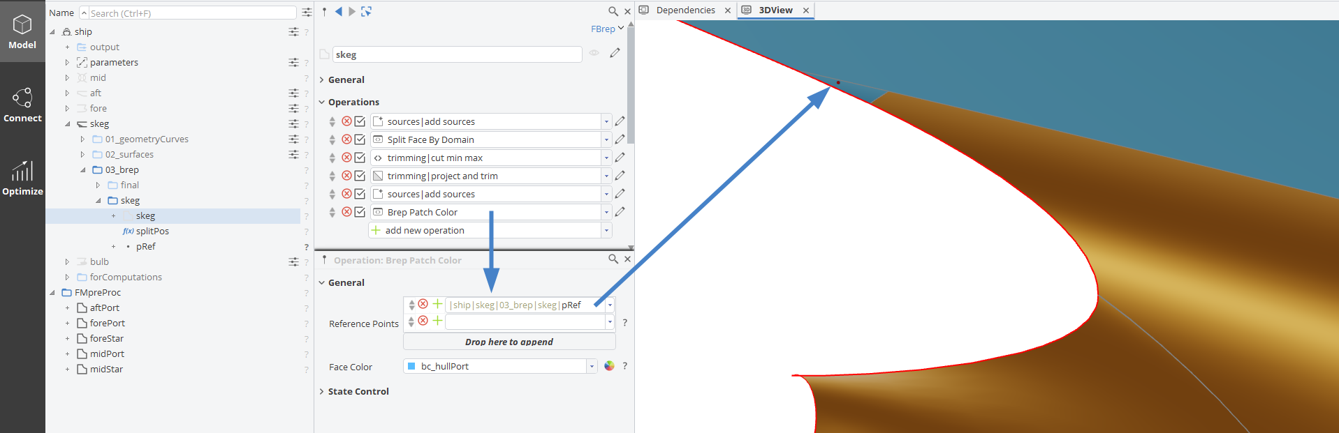
By setting up the boundary patches for HEXPRESS like this, we can successfully avoid generating very narrow or highly skewed cells under such circumstances. It is important to note that edges between patches of the same color will not be preserved in the resulting mesh.
Before mirroring we want to address the hub face which is not yet a part of the geometric model. We can do so using the Close Planar Open Edges BRep Operation. To reference the circular edge of the hub we will position a point along the curve |ship|skeg|01_geometryCurves|03_hub|hub using a Curve Based > Position on Curve point at t = 0.5.
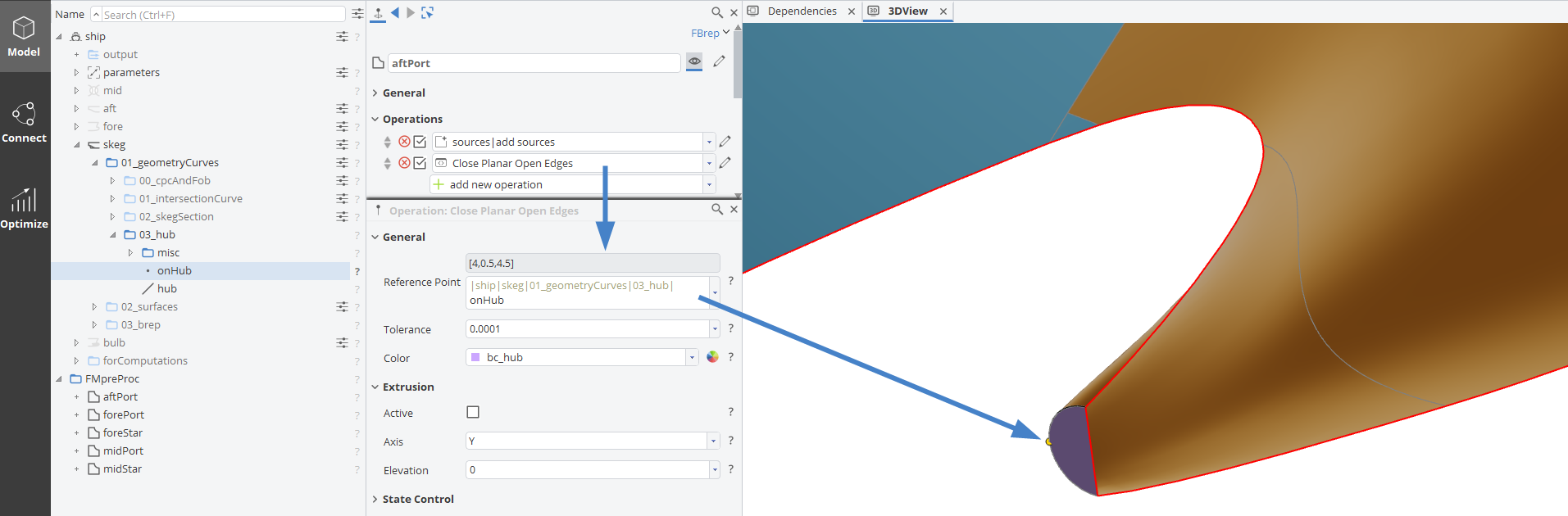
The starboard side of the aft will again be a mirror image of the port side. The hull color can be replaced, for the skeg a new color "bc_skegStar" needs to be created in the process. This differentiation is necessary to maintain the sharp trailing edge of the skeg similar to how the stem was treated earlier in the set up.
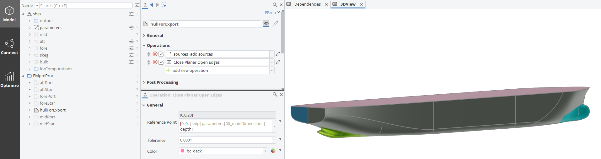
All components can now be combined into a single, watertight BRep. After adding all the sources, the deck is closed via a Close Planar Open Edges, similarly to how the hub cap has been treated.
Domain and Export Format
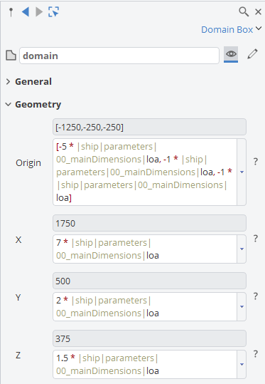
As a final step we are going to create a solid domain for the export. Since we need a symmetric domain to account for the two separate sides of the skeg and bulb we will start by setting up a domain box from CAD > BReps > More > Box Domain. For the size and position we will use the length over all (LOA) of the ship as a reference.
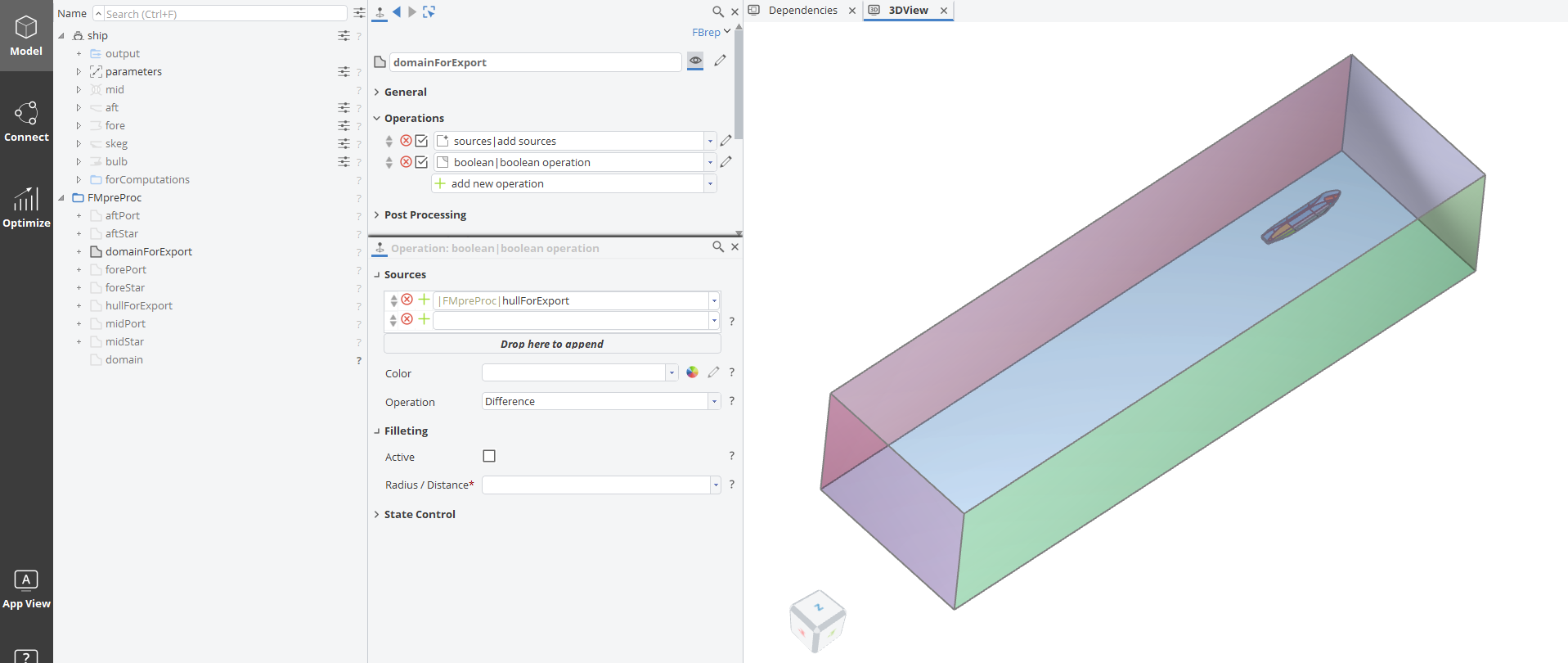
From there, a new BRep is created and the hull is removed in a Boolean Difference Operation.
To make sure the meshing process runs smoothly, a Design of Experiments (i.e. a Sobol run) evaluating the number of open edges of a Trimesh based on the final domain is good practice.
CAESES Project File
If you want to take a look at the finalized model you can find the resulting CAESES project file fine-marine-pre-processing.cdb here: